Dateq BCS70 User manual
BCS70
USER MANUAL

EN Dateq BCS70 Manual Safety instructions 2
Safety instructions
1All safety instructions, w arnings and operating instructions must be read first.
2All w arnings on the equipment must be heeded.
3The operating instructions must be f ollow ed.
4Keep the operating instructions for future reference.
5The equipment may never be used in the immediate vicinity of w ater; make sure that
w ater and damp cannot get into the equipment.
6The equipment may only be installed or fitted in accordance w ith the manufacturer's
recommendations.
7The equipment must be installed or fitted such that good ventilation is not obstructed in
any w ay.
8The equipment may never be installed in the immediate vicinity of sources of heat, such
as parts of heating units, boilers, and other equipment w hich generates heat (including
amplif iers).
9Connect the equipment to a pow er supply of the correct voltage, using only the cables
recommended by the manufacturer, as specified in the operating instructions and/or
show n on the connection side of the equipment.
10 The equipment may only be connected to a legally approved earthed mains pow er
supply.
11 The pow er cable or pow er cord must be positioned such that it cannot be w alked on in
normal use, and objects w hich might damage the cable or cord cannot be placed on it
or against it. Special attention must be paid to the point at w hich the cable is attached to
the equipment and w here the cable is connected to the pow er supply.
12 Ensure that foreign objects and liquids cannot get into the equipment.
13 The equipment must be cleaned using the method recommended by the manufacturer.
14 If the equipment is not being used for a prolonged period, the pow er cable or pow er
cord should be disconnected from the pow er supply.
15 In all cases w here there is a risk, follow ing an incident, that the equipment could be
unsafe, such as:
• if the pow er cable or pow er cord has been damaged
• if foreign objects or liquids (including w ater) have entered the equipment
• if the equipment has suffered a f all or the casing has been damaged
• if a change in the performance of the equipment is noticed it must be checked by
appropriately qualified technical staff .
16 The user may not carry out any w ork on the equipment other than that specified in the
operating instructions.

EN Dateq BCS70 Manual Introduction 3
Introduction
The Dateq BCS70 is a modular mixer unit which has been designed specially for use in radio
studios. The mixer unit consists of a frame (a split version is also available) with external power
supply, combined master / monitor module and various input modules.
Frame
The frame can take a maximum of 18 input modules, a script space and a master module. The
input modules can be positioned where wished in the frame. The BCS78 master / monitor
module is positioned at the right of the frame and the script space is positioned preferably in the
middle. A meter bridge is positioned on top of the frame. This contains a BCS62 VU, a 50
segment LED-bar meter with peak hold or a 101 segment Neon-bar meter. The meter bridge can
be expanded to include a BCS81 DCF-77 controlled clock / timer and a BCS68-2 extra set of 4
LED bar meters of 40 segments for reading CUE and AUD levels for example.
Pow er Supply
The BCS70 has an external power supply to prevent magnetic interference from the transformer.
The power supply is 19" wide, 2HE high and is connected to the frame via a 7-pin XLR
connector.
Input modules
There are many different modules available. All the modules (mono, stereo and telephone) are
available with and without tone control. The mono and stereo modules have two inputs which
are identical as regards facilities and which are available both with and without gain control.
The telephone module does not have a gain control because it is assumed that the external,
preferably digital, hybrid has an auto-gain function. Every module is equipped with trimmers to
allow the volume of all audio inputs and outputs to be set precisely. These controls are sited on
the modules' connector boards. The use of jumpers for modules is now minimal, most user
functions can be set via the software using a simple Setup function.
Microcontrollers
Each module is controlled by its own microcontroller. This controls all audio connections and
connected equipment. The microcontrollers can communicate with each other to allow 'global'
functions such as the control room mute and the Setup mode. Because all 'intelligent' functions
are contained within the software of the microcontroller, user-specific operation can easily be set
up without hardware modifications. What the user must specify is the type of equipment
connected to an input. There are a maximum of 16 preferred settings from which to choose.
Controls such as pulse/continuous contact, internal or external tally can be changed by this
means. Some 'non-standard' controls are pre-programmed, such as the standard setting for
Nautilus JukeBox automation, 360 Systems DigiCart and Denon CD and MD players.
Product support
If you have any questions concerning the BCS70, its accessories or other products, please
contact:
Dateq Audio Technologies B.V.
De Paal 37
1351 JG Almere
The Netherlands
Telephone: +31 (36) 54 72 222
Fax: +31 (36) 53 17 776
E-mail: [email protected]
Internet: www.dateq.nl

EN Dateq BCS70 Manual Installation 4
Installing the mixer unit
The BCS70 is supplied as standard w ithout a cabinet or connector cables. It is possible to
make cables for connection to the Sub-D connectors of the various input and output modules
in-house. In that case, metal caps for the Sub-D connectors and cables w ith a separate
screening should be used, as per the CE norms.
Breakout boxes
Another possibility f or connecting the mixer unit is to make use of so-called 'breakout boxes'.
All non-standard Sub-D connector on the rear of the BCS70 can be split up into more usual
connector types such as XLR plugs and TSR jacks. Breakout boxes should be connected to
the BCS70 using shielded Sub-D cable.
Installation into the cabinet
The BCS70 frame fits into an opening of 1050 x 547 x 75 mm (W x H x D). Without the meter
bridge the mixer unit projects 72 mm above the table top, w ith the meter bridge the highest
point is 205 mm. See also the dimensioned draw ing below .
EN Dateq BCS70 Manual Installation 5
Setting the type of equipment connected
Each module has a quad DIP sw itch for selecting the type of control of equipment connected
to an input. Therefore, on the BCS71 and BCS72 you w ill find tw o sets of DIP-sw itches (one
for each input). On the BCS73 you w ill f ind a set of DIP-s w itches f or other f unctions.
BCS71 and BCS72 DIP-sw itch settings
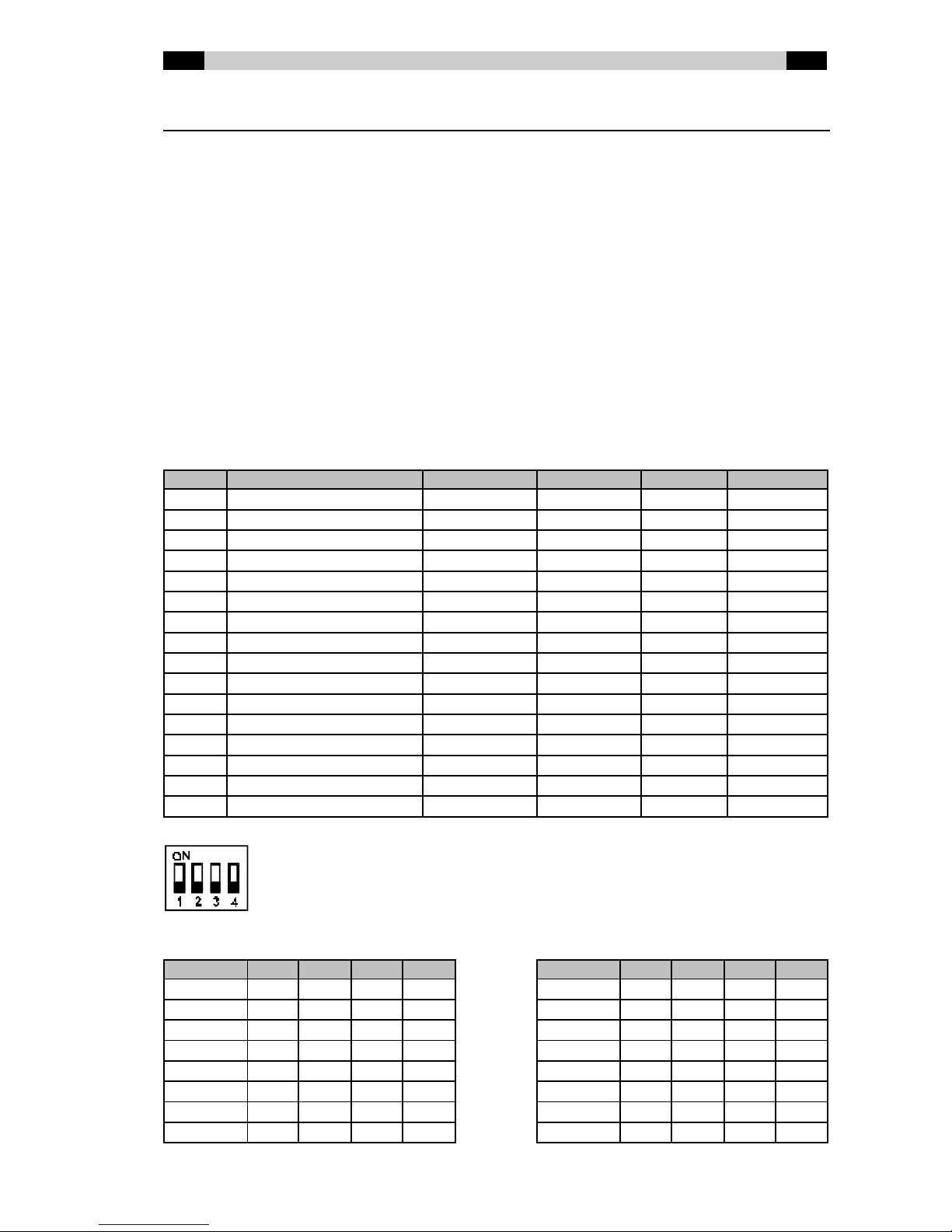
For each input you can select from 16 types of operation for the equipment connected.
Whereas previously the only choice w as pulse or continuous contacts, now equipment-
specific operation can also be selected. This concerns equipment w hich, in addition to
standard operation, also has special functions or has to be operated in a non-standard w ay.
As standard, a choice can be made betw een continuous or pulse contacts (short or long
pulses), indication of internal or external tally on the ON and OFF buttons, giving a start pulse
again by pressing the ON button (Restart) and activating the CUE function by putting the
equipment w ith sw itched off module into the 'PLAY' state (Remote Cue).
Equipment control patterns available:
Type Description Start / Stop Tally Restart Remote Cue
0 Normal consumer (default) Continuous Internal No No
1 Normal consumer Pulse 100ms Internal No No
2 Normal consumer Pulse 500ms Internal No No
3 Normal pro Continuous External No No
4 Normal pro Pulse 100ms External No No
5 Normal pro Pulse 500ms External No No
6 Reserved
7 Reserved
8 360 Systems DigiCart Pulse 100ms External Yes Yes
9 Denon DN- xxxF Continuous External No Yes
10 Tascam DA-30 Pulse 1s External No Yes
11 Reserved
12 Reserved
13 Tally switches on/off Continuous Internal No No
14 Tiesseci TS-35 Pulse 500ms Internal Yes No
15 Nautilus JukeBox Special Special No Yes
Í
ÍÍ
ÍType 0 (default)
The sw itches can easily be set w ith a ball-point pen.
DIP sw itch positions corresponding to certain types of equipment:
Type 1 2 3 4 Type 1 2 3 4
0 Off Off Off Off 8 Off Off Off ON
1 ON Off Off Off 9 ON Off Off ON
2 Off ON Off Off 10 Off ON Off ON
3 ON ON Off Off 11 ON ON Off ON
4 Off Off ON Off 12 Off Off ON ON
5 ON Off ON Off 13 ON Off ON ON
6 Off ON ON Off 14 Off ON ON ON
7 ON ON ON Off 15 ON ON ON ON

EN Dateq BCS70 Manual Installation 6
Use of non-standard equipment
One of the patterns given in the table on the previous page w ill suffice for most equipment. In
order to be able to connect up equipment w ith non-standard operation or tally outputs, it is
possible that other control softw are w ill be required, for example, or that any tally outputs w ill
have to be combined. In case of doubt or for special requirements, please contact Dateq.
BCS73 DIP-sw itch settings
The BCS73 w as originally designed for use w ith an external Telos ONE digital hybrid.
Therefore, connecting the ‘remote control’ cable is very easy. By default, the Telos ONE is
controlled by pulses. If you w ant to use a hybrid that must be controlled in a non-Telos w ay,
you can use DIP-sw itch settings corresponding to a control-pattern from the table below :
Control patterns available:
DIP-switch 1 DIP-switch 2 DIP-switch 3 Description Hybrid On / Off
Off Off Off Telos ONE (default) Pulse 100ms
Off ON Off Long pulses Pulse 500ms
ON - (don’t care) Off Continuous Continuous
Off Off ON DATEQ TH-2 Inverted pulse 100ms
Off ON ON Inverted long Inverted long pulse 500ms
ON - (don’t care) ON Continuous inverted Continuous inverted
The Telos ONE is a digital hybrid. If you use this type of hybrid, the rejection of return audio in
your program material is so high that you may w ant to allow talk-back to a caller during an on-
air situation. You can use DIP-sw itch 4 to select talk-back w hen on-air. If you use passive
hybrids or active hybrids w ith a low er rejection ratio, it is advisable to disable the talk-back
option. Otherw ise it is possible to hear the talk-back audio in your program w ith possible nasty
consequences...
Talkback if hybrid is on-air:
DIP-switch 4 Description
Off No talk-back if the hybrid’s audio is used in your program
ON Talk-back allowed, even if the hybrid’s audio is used in your program

EN Dateq BCS70 Manual BCS71(GE) dual mono input module 7
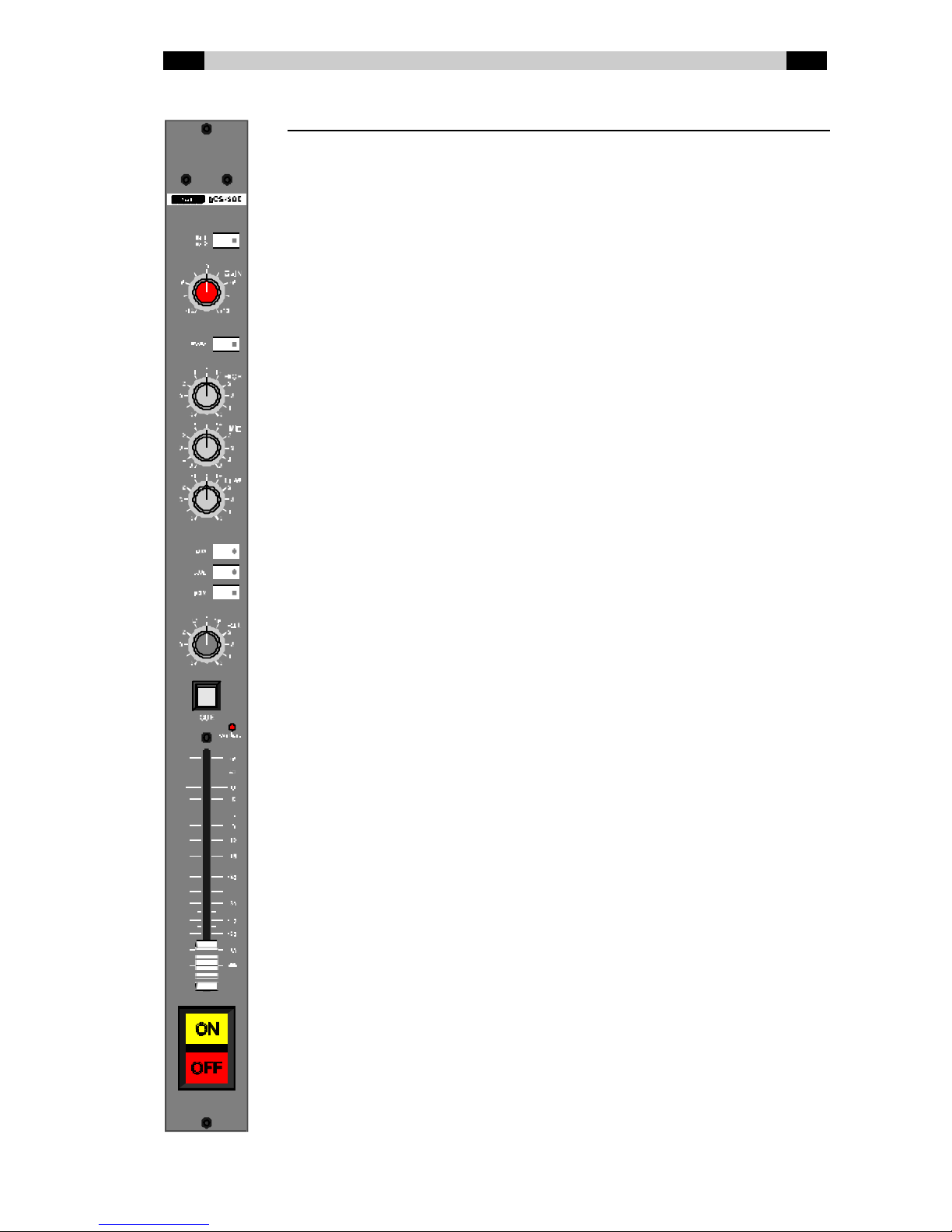
BCS71(GE) dual mono input module
BCS71 Mono module w ithout gain or tone control
BCS71E Mono module w ithout gain, w ith tone control
BCS71G Mono module w ith gain, w ithout tone control
BCS71GE Mono module w ith gain and tone control
Mic / Line Input selection. Sw itch pressed in is Line (LED lights
up).
Gain Volume presetting (only on the BCS71G and
BCS71GE). Limited adjustment range: ± 12dB.
Low Cut Low cut f ilter (20/80 Hz). Sw itch pressed in (LED
lights up) is active.
Hig h High tone control (only on the BCS71E and
BCS71GE). Shelving: ± 12dB @ 12kHz.
Mid Mid tone control (only on the BCS71E and BCS71GE).
Bell curve: ± 16dB @ 1.3 kHz.
Low Low tone control (only on the BCS71E and
BCS71GE). Shelving: ± 16dB @ 60 Hz.
AUX / AUD / PGM Bus routing sw itches. The sw itch pressed in (LED
lights up) indicates that the signal is being routed
from the module to the bus concerned. AUX can be
set to PRE or POST f ader w ith jumpers.
PAN Panorama control. The signal is placed at the desired
position in the stereo image.
CUE Monitoring. This button lights up green if the CUE
function on this module is active. The button lights up
red if an (external) mute is active.
Ove r load This LED lights up if the signal level anyw here in the
module is too high and distortion can or does occur
(the limit is 6 dB under clip level).
Fade r 100mm long volume control. Depending on the jumper
settings on the module, the volume on the AUX bus is
dependent (POST) or independent (PRE) of the
position of this fader.
ON / OFF Sw itches w ith w hich the channel can be turned on
and off (if button start w as configured) and/or the
equipment connected can be started / stopped. The
lamps in the sw itches can light up dependent on the
channel status (internal tally) or can be controlled by
connected equipment (external tally).
EN Dateq BCS70 Manual BCS71(GE) dual mono input module 8
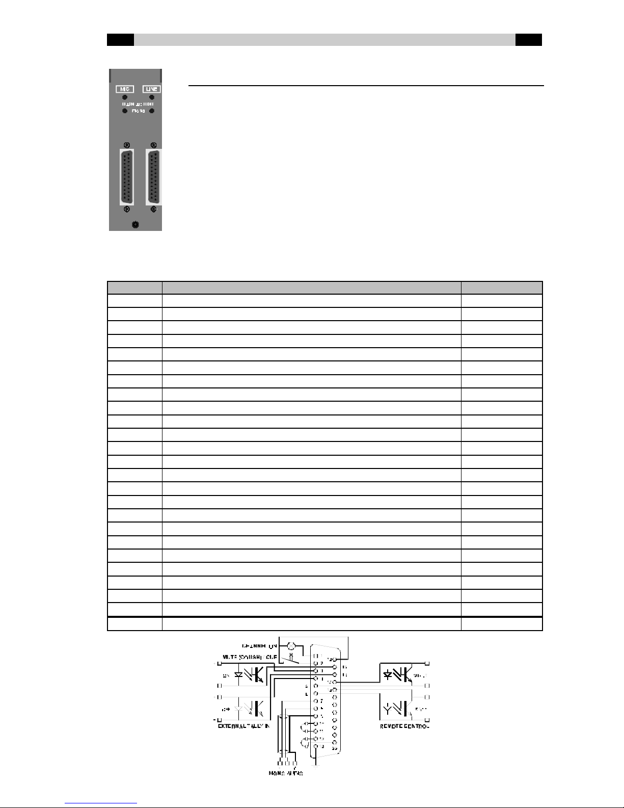
BCS71(GE) connector board
GAIN ADJUST The input-level can be trimmed separately for both
the microphone and line input. Use a small
screw driver to adjust the trimmers in the holes
marked ‘mono’.
MIC Mono microphone input on 25-pin female Sub-D
connector.
LINE Electronically balanced mono line input on 25-pin
female Sub-D connector.
BCS71(GE) Audio and Control Input / Output (Sub-D 25-pin female)
Pin Function Type
1 Channel ON / External CUE lamp Out
14 External CUE lamp / External CUE or Cough switch D-GND
2 External CUE or Cough switch In
15 External tally ON - (opto-coupler cathode) In
3 External tally ON + (opto-coupler anode) In
16 External tally OFF - (opto-coupler cathode) In
4 External tally OFF + (opto-coupler anode) In
17 Remote control Start (opto-coupler collector) Out
5 Remote control Start (opto-coupler emitter) Out
18 Remote control Stop (opto-coupler collector) Out
6 Remote control Stop (opto-coupler emitter) Out
19 -
7 Audio Mono + In
20 -
8 Audio Mono - In
21 -
9 Audio GND A-GND
22 -
10 Insert Send + (no insert used: connect to pin 11) Out
23 -
11 Insert Return + (no insert used: connect to pin 10) In
24 -
12 Insert Return - (no insert used: connect to pin 25) In
25 Insert GND (no insert used: connect to pin 12) Out
13 Frame GND FRAME
EN Dateq BCS70 Manual BCS71(GE) dual mono input module 9
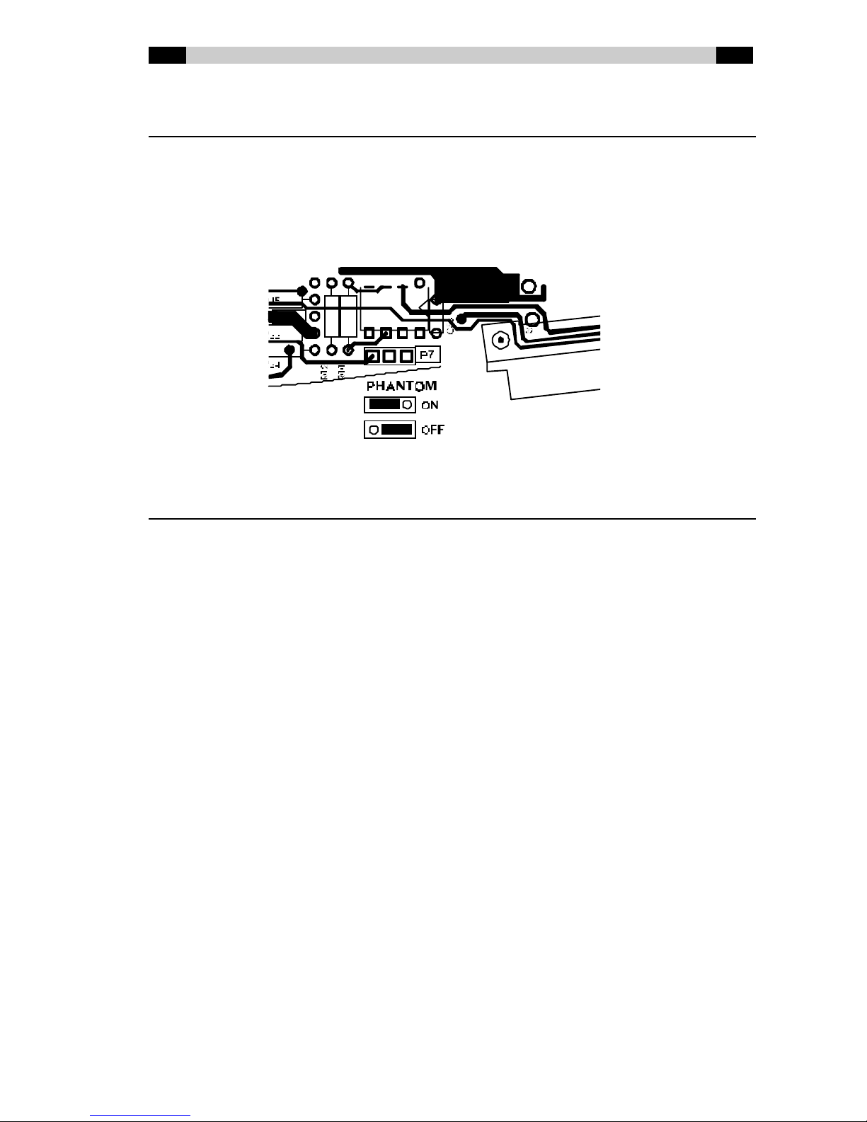
Phantom power supply
Non-dynamic microphones usually need a 48V external pow er supply. If this pow er has to be
supplied by the BCS70, place jumper P7 in the ‘ON’ position. +48VDC (related to the (0)-input)
will be supplied to both the (+) and the (-) input.
Jumper P7 is positioned next to the bus connector of the BCS71(GE) module. The factory
default for this jumper is ‘OFF’.
Warning: central muting of multiple microphone channels
To prevent the line1/line2-selection of the input-modules from malfunctioning, pins #14
(common Cue / Cough) of the input-connectors can not be connected to each other. When
using a system that mutes multiple microphone channels with the ‘cough’-input (like FlexCom
FXS-D extensions), please note that if this system uses a common ground (like the FXS-D),
don’t connect this ground to pin #14 (common Cue / Cough), but rather use #13 (Frame) or
#25 (Ground).
EN Dateq BCS70 Manual BCS72(GE) dual stereo input module 10
BCS72(GE) dual stereo input module
BCS72 Stereo module w ithout gain or tone control
BCS72E Stereo module w ithout gain, w ith tone control
BCS72G Stereo module w ith gain, w ithout tone control
BCS72GE Stereo module w ith gain and tone control
Line 1 / Line 2 Input selection. Sw itch pushed in (LED is lit up) is
Line 2.
Gain Volume presetting (only on the BCS72G and
BCS72GE). Limited adjustment range: ± 12dB.
Mono Makes the stereo input signal mono. Sw itch pushed
in (LED lit up) is active.
Hig h High tone control (only on the BCS72E and
BCS72GE). Shelving: ± 12db @ 12 kHz.
Mid Mid-tone control (only on the BCS72E and
BCS72GE). Bell curve: ± 16dB @ 1.3 kHz.
Low Low tone control (only on the BCS72E and
BCS72GE). Shelving: ± 16dB @ 60 Hz.
AUX / AUD / PGM Bus routing sw itches. Sw itch pushed in (LED lit up)
indicates that the signal is being routed from the
module to the bus concerned. AUX can be set to PRE
or POST fader w ith jumpers.
BAL Balance control. This is used to set the balance
betw een the left and right channels.
CUE Monitoring. This button lights up green if the CUE
function on this module is active. The button lights up
red if an (external) mute is active.
Ove r load This LED lights up if the signal level anyw here in the
module is too high and if distortion can or does occur
(the limit is at 6 dB under clip level).
Fade r 100 mm long volume control. Depending on the
jumper settings on the module, the volume is
dependent on the AUX bus (POST) or independent
(PRE) of the position of this fader.
ON / OFF Sw itches w ith w hich the channel can be turned on
and off (if button start is configured) and/or the
connected equipment can be started / stopped. The
lamps in the sw itches can light up dependent on the
channel status (internal tally) or can be controlled by
connected equipment (external tally).

EN Dateq BCS70 Manual BCS72(GE) dual stereo input module 11
BCS72(GE) connector board
GAIN ADJUST The input level can be trimmed separately for both
channels of both inputs. Use a small screw driver to
adjust the trimmers in the holes marked 'left' and
'right'.
LINE 1 First stereo line input on 25-pin f emale Sub-D
connector.
LINE 2 Second stereo line input on female 25-pin Sub-D
connector. Identical facilities to the first line input.
BCS72(GE) Audio and Control Input / Output (Sub-D 25-pin female)
Pin Function Type
1 Channel ON / External CUE lamp Out
14 External CUE lamp / External CUE or Cough switch D-GND
2 External CUE or Cough switch In
15 External tally ON - (opto-coupler cathode) In
3 External tally ON + (opto-coupler anode) In
16 External tally OFF - (opto-coupler cathode) In
4 External tally OFF + (opto-coupler anode) In
17 Remote control Start (opto-coupler collector) Out
5 Remote control Start (opto-coupler emitter) Out
18 Remote control Stop (opto-coupler collector) Out
6 Remote control Stop (opto-coupler emitter) Out
19 Audio Left + In
7 Audio Right + In
20 Audio Left - In
8 Audio Right - In
21 Audio Left GND A-GND
9 Audio Right GND A-GND
22 Insert Send Left + (no insert used: connect to pin 23) Out
10 Insert Send Right + (no insert used: connect to pin 11) Out
23 Insert Return Left + (no insert used: connect to pin 22) In
11 Insert Return Right + (no insert used: connect to pin 10) In
24 Insert Return Left - (no insert used: connect to pin 25) In
12 Insert Return Right - (no insert used: connect to pin 25) In
25 Insert GND (no insert used: connect to pins 12 and 24) Out
13 Frame GND FRAME
EN Dateq BCS70 Manual BCS73(E) external hybrid input module 12
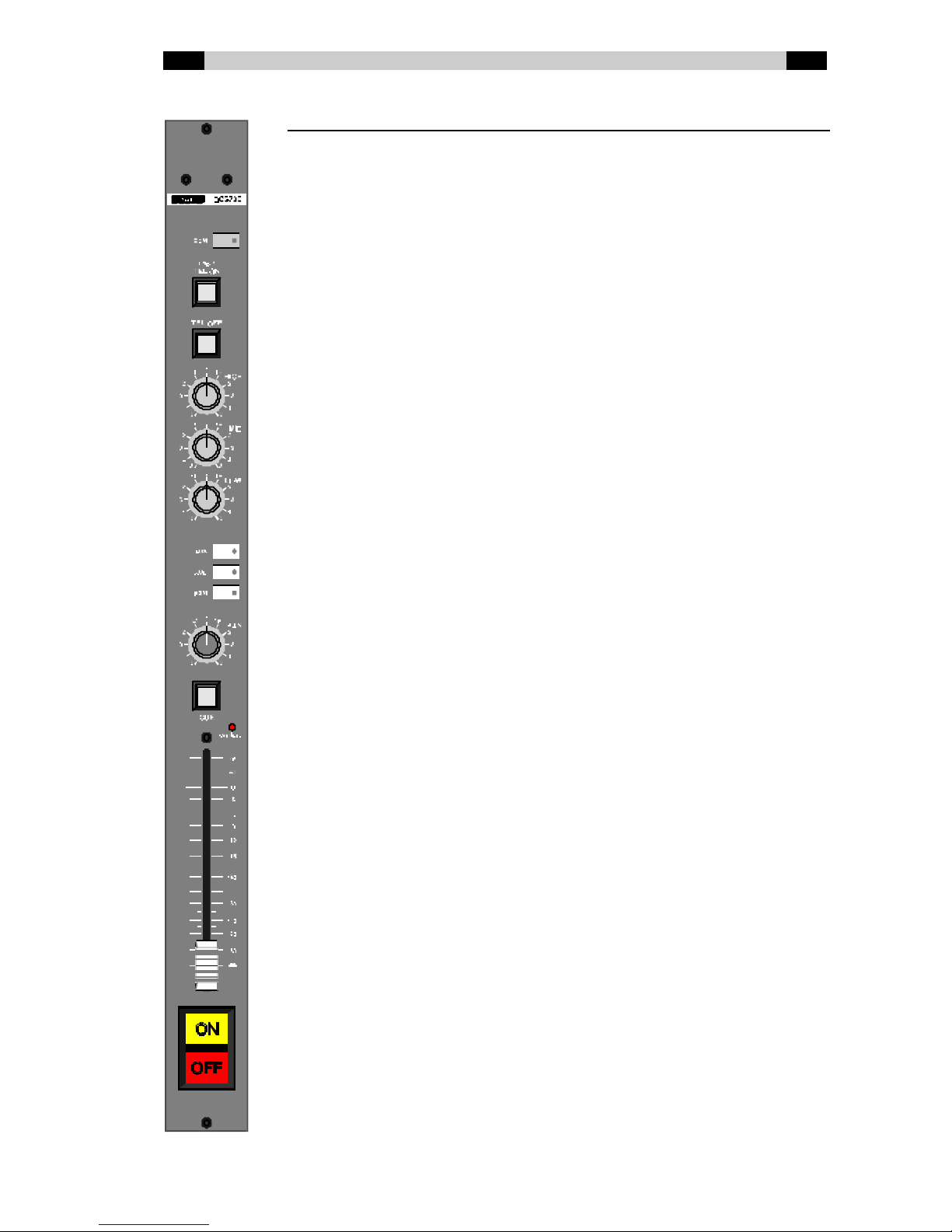
BCS73(E) external hybrid input module
BCS73 Telephone module w ithout tone control
BCS73E Telephone module w ith tone control
Com Sw itches the signal from the telephone hybrid to the
COM bus, and sw itches the return signal from the
COM bus to the hybrid (see also QDM²).
TEL ON (ringer) Sw itches the external hybrid on (the lamp in this
button flashes quickly if a ring is detected).
TEL OFF Sw itches the external hybrid off if the channel is off
(keep pressed for 1 second to prevent operating
errors).
Hig h High tone control (only on the BCS73E). Shelving: ±
12dB @ 3 kHz.
Mid Mid tone control (only on the BCS73E). Bell curve: ±
16dB @ 1.3 kHz.
Low Low tone control (only on the BCS73E). Shelving: ±
16dB @ 600 Hz.
AUX / AUD / PGM Bus routing sw itches. Sw itch pressed in (LED lit up)
indicates that the signal is being routed from the
module to the bus concerned. AUX can be set on
PRE or POST fader w ith jumpers.
PAN Panorama control. The signal is positioned at the
desired place in the stereo image w ith this.
CUE Monitoring. This button lights up green if the CUE
function on this module is active. The hybrid then
gets the CUE bus as return (see also QDM²). CUE
can not be selected if the channel is on. The button
lights up red if a mute is active.
Ove r load This LED lights up if the signal level anyw here in the
module is too high and distortion can or does occur
(the limit is 6 dB under clip level).
Fade r 100 mm long volume control. Depending on the
jumper settings on the module the volume is
dependent on the AUX bus (POST) or independent
(PRE) of the position of this fader.
ON / OFF Sw itches w ith w hich the channel can be turned on
and off (if button start is configured) and / or the
equipment connected can be started / stopped. The
lamps in the sw itches light up dependently of the
channel status (intern tally).

EN Dateq BCS70 Manual BCS73(E) external hybrid input module 13
BCS73(E) connector board
GAIN ADJUST The levels of the audio signal from the external
hybrid (receive) and the return audio signal to the
external hybrid (send) can be trimmed. Use a small
screw driver to adjust the trimmers in the holes
marked ‘send’ and ‘receive’.
AUDIO Electronically balanced audio input and output f or
audio coming from the external hybrid and return
audio to the external hybrid (QDM² return) on 9-pin
female Sub-D connector.
REM OTE Remote control for the external hybrid on 9-pin male
Sub-D connector.
BCS73(E) Audio (Sub-D 9-pin female)
Pin Function Type
1 Audio Send + (audio to external hybrid) Out
6 Audio Send - (audio to external hybrid) Out
2 Audio Send GND A-GND
7 GND A-GND
3 Frame GND FRAME
8 GND A-GND
4 Audio Receive GND A-GND
9 Audio Receive - (audio from external hybrid) In
5 Audio Receive + (audio from external hybrid) In
BCS73(E) Remote (Sub-D 9-pin male, Telos ONE compatible)
Pin Function Type
1 External hybrid ON switch (opto-coupler collector) Out
6 External hybrid ON / OFF switch common(opto-couplers emitter) Out
2-
7 External hybrid OFF switch (opto-coupler collector) Out
3-
8-
4-
9 Telephone line ‘A’-lead (used for ring-detector only) In
5 Telephone line ‘B’-lead (used for ring-detector only) In

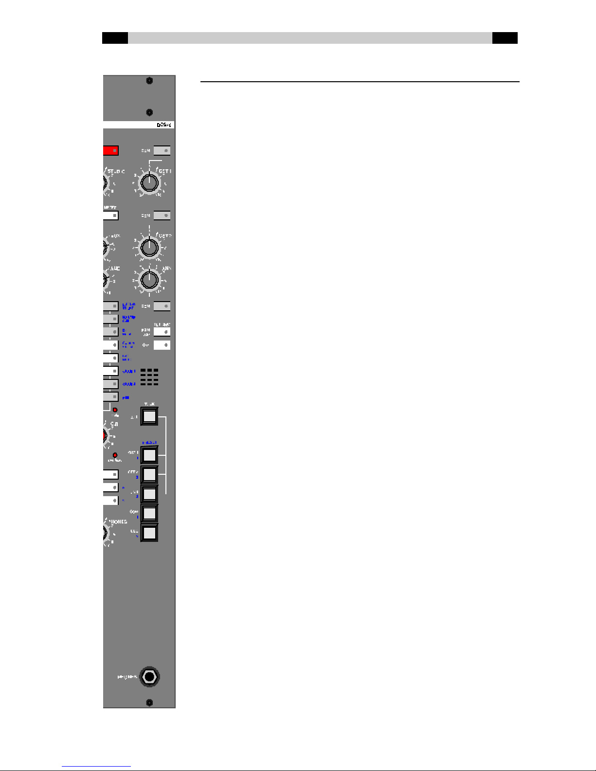
EN Dateq BCS70 Manual BCS78 master (monitor) module 14
BCS78 master (monitor) module
The master module is constructed using a new concept, w ith
microprocessor control and audio matrix to take care of routing to the
various outputs. Many of the buttons have a double function (see blue
print) w hich is used in the Setup mode.
SETUP This is used to select the Setup mode. The LED
in this button flashes in Setup mode.
STUDIO Volume control for the Studio output.
METER PGM / C.R. Source selection for the meter in the meter
bridge: the PGM signal or the signal selected for
the Control Room (sw itch pushed in).
AUX Volume control for the AUX output.
AUD Volume control for the AUD output.
AIR..CUE Selection of the signal on the Control Room
output (and on the Phones output). The active
selection can be seen from the LED w hich lights
up under a button. In Setup mode these LED’s
flash w hen the associated Setup option is
selected. The LED’s in the AIR and PGM button
are dimmed w hen MASTER-CUE is used in
combination w ith MIX.
Mute This LED lights up if the Control Room output is
automatically sw itched off .
C.R. Volume control for the Control Room output.
Ove r load This LED lights up if the signal level in the master
module is too high.
Mono Sw itches the signal f rom the Control Room to
mono.
PGM / AIR This is used to select to w hich signal the DJ w ill
automatically listen if a DJ channel is on: AIR or
PGM. This selection also determines w hich of
these signals is mixed if another of the signals
from the CR selector panel is being monitored in
combination w ith the MIX function.
MIX Mixes the dimmed signal chosen w ith the
PGM/AIR button w ith the signal selected w ith the
CR selector panel.
PHONES Volume control for the Phones output.
EN Dateq BCS70 Manual BCS78 master (monitor) module 15
BCS78 master (monitor) module
COM (guest 1) Sw itches the signal from the COM bus to the
headphone output of Guest 1 and the signal
from the input module(s) configured as Guest 1
to the COM bus.
GST 1 Volume control for the Guest 1 headphone
output.
COM (guest 2) Sw itches the signal from the COM bus to the
headphone output of Guest 2 and the signal
from the input module(s) configured as Guest 2
to the COM bus.
GST 2 Volume control for the Guest 2 headphone
output.
ANN Volume control for the Announcer headphone
output.
COM (announcer) Sw itches the signal from the COM bus to the
announcer headphone output and the signal
from the input module(s) configured as
Announcer to the COM bus.
PGM / AIR(tbk src) Selects the PGM or AIR signal as source for the
phones outputs of Guest 1, Guest 2 and
Announcer. The LED under this button lights up
if AIR is selected.
C.R. (tbk src) Selects the signal selected on the Control Room
selector panel as the source for the headphone
outputs of Guest 1, Guest 2 and Announcer.
The LED under this button lights up if CR is
selected, and the selection made w ith PGM / AIR
is canceled.
MIC Built-in microphone for talkback
TALK ALL The DJ / technician can talk to Guest 1, Guest 2
and Announcer at the same time.
TALK GST 1 The DJ / technician can talk to Guest 1 using this
button.
TALK GST 2 The DJ / technician can talk to Guest 2 using this
button.
TALK ANN The DJ / technician can talk to the Announcer
using this button.
TALK COM The DJ / technician can talk to everyone w ho is
routed to the COM bus.
TALK CUE The DJ / technician can talk to all telephone
modules on w hich the CUE function is active
(these modules have the CUE bus as return, see
also QDM²).
PHONES Headphone output for the DJ / technician.

EN Dateq BCS70 Manual BCS78 master (monitor) module 16
BCS78 connector board
The BCS78 master (monitor) module has a number of connectors for audio inputs and outputs
and on-air indicating on the connector board.
AIR / SPARES 15-pin female Sub-D connector to w hich the balanced audio signals
for AIR, SPARE 1 and SPARE 2 can be connected. These inputs are
not electrically isolated. If a tuner w hich is connected to a cable
netw ork is connected up this can lead to an earth loop. To prevent this
it is advisable to have an isolating transformer in the aerial or audio
cable(s). These inputs can, for example, also be used for post-tape
check w ith recordings.
ANN / GST 1 / GST 2 15-pin female Sub-D connector w ith three independent stereo outputs
to w hich headphones of Announcer, Guest 1 and Guest 2 can be
connected directly. Also unbalance stereo Studio output.
INSERTS Balanced insertion points in the stereo PGM signal.
CR-L / CR-R Electronically balanced male XLR-3 outputs. These are used for
connecting the amplifier to the speakers in the Control Room. The
Control Room selector sw itches are used to select w hich signal can
be heard via this output. The volume of this output is determined w ith
the C.R. volume control. The Control Room output is automatically
sw itched off to prevent acoustic feedback.
AIR- L / AIR- R T RIM The level of the AIR input can be trimmed. Use a small screw driver to
adjust the trimmers.
DIRECTOR 15-pin female Sub-D connection for an optional director's post.
ON-AIR 1 / ON-AIR 2 The ON AIR outputs are intended for connecting indicators, such as an
'ON AIR' lamp. The modules w hich these ON AIR outputs activate can
be set using the Setup mode. If there are microphones in tw o rooms,
for example a DJ microphone in the Control Room and other
microphones in the studio, then a separate 'ON AIR' indication can be
connected for each room. Configure the DJ microphone channel as ON
AIR 2 and the other microphone channels as ON AIR 1.

EN Dateq BCS70 Manual BCS78 master (monitor) module 17
BCS78 Director (Sub-D 9-pin female)
Pin Function Type
1 BCSBus Data
6 Audio GND A-GND
2 +12V power supply POWER
7 D-GND power supply POWER
3 Audio Right Out
8 Audio Left Out
4 Audio GND A-GND
9 Director Mic + In
5 Director Mic - In
BCS78 Ann / Guest1 / Guest2 / Studio (Sub-D 15p female)
Pin Function Type
1 Announcer Headphones Right Out
9 Announcer Headphones Common Out
2 Announcer Headphones Left Out
10 -
3 Guest 2 Headphones Right Out
11 Guest 2 Headphones Common Out
4 Guest 2 Headphones Left Out
12 -
5 Guest 1 Headphones Right Out
13 Guest 1 Headphones Common Out
6 Guest 1 Headphones Left Out
14 -
7 Studio Output Right Out
15 Studio GND A-GND
8 Studio Output Left Out
BCS78 CR-L / CR-R (XLR 3p male)
Pin Function Type
1 Audio GND A-GND
2 Audio + Out
3 Audio - Out
BCS78 ON-AIR 1 / ON-AIR 2 (TRS Jack 3p)
Pin Function Type
Tip On-Air Opto coupler collector Out
Ring -
Sleeve On-Air Opto-coupler emitter Out

EN Dateq BCS70 Manual BCS78 master (monitor) module 18
BCS78 Inserts (Sub-D 9-pin female)
Pin Function Type
1 Frame GND FRAME
6 Send Right + (no insert used: connect to pin 7) Out
2 Return Right - (no insert used: connect to pin 3) In
7 Return Right + (no insert used: connect to pin 6) In
3 Audio GND (no insert used: connect to pin 2) A-GND
8 Send Left + (no insert used: connect to pin 9) Out
4 Return Left - (no insert used: connect to pin 5) In
9 Return Left + (no insert used: connect to pin 8) In
5 Audio GND (no insert used: connect to pin 4) A-GND
BCS78 Air / Spare 1 / Spare 2 (Sub-D 15p female)
Pin Function Type
1 Air GND A-GND
9 Air Right + In
2 Air Right - In
10 Air Left + In
3 Air Left - In
11 Spare 1 GND A-GND
4 Spare 1 Right + In
12 Spare 1 Right - In
5 Spare 1 Left + In
13 Spare 1 Left - In
6 Spare 2 GND A-GND
14 Spare 2 Right + In
7 Spare 2 Right - In
15 Spare 2 Left + In
8 Spare 2 Left - In
EN Dateq BCS70 Manual BCS70 connector board 19
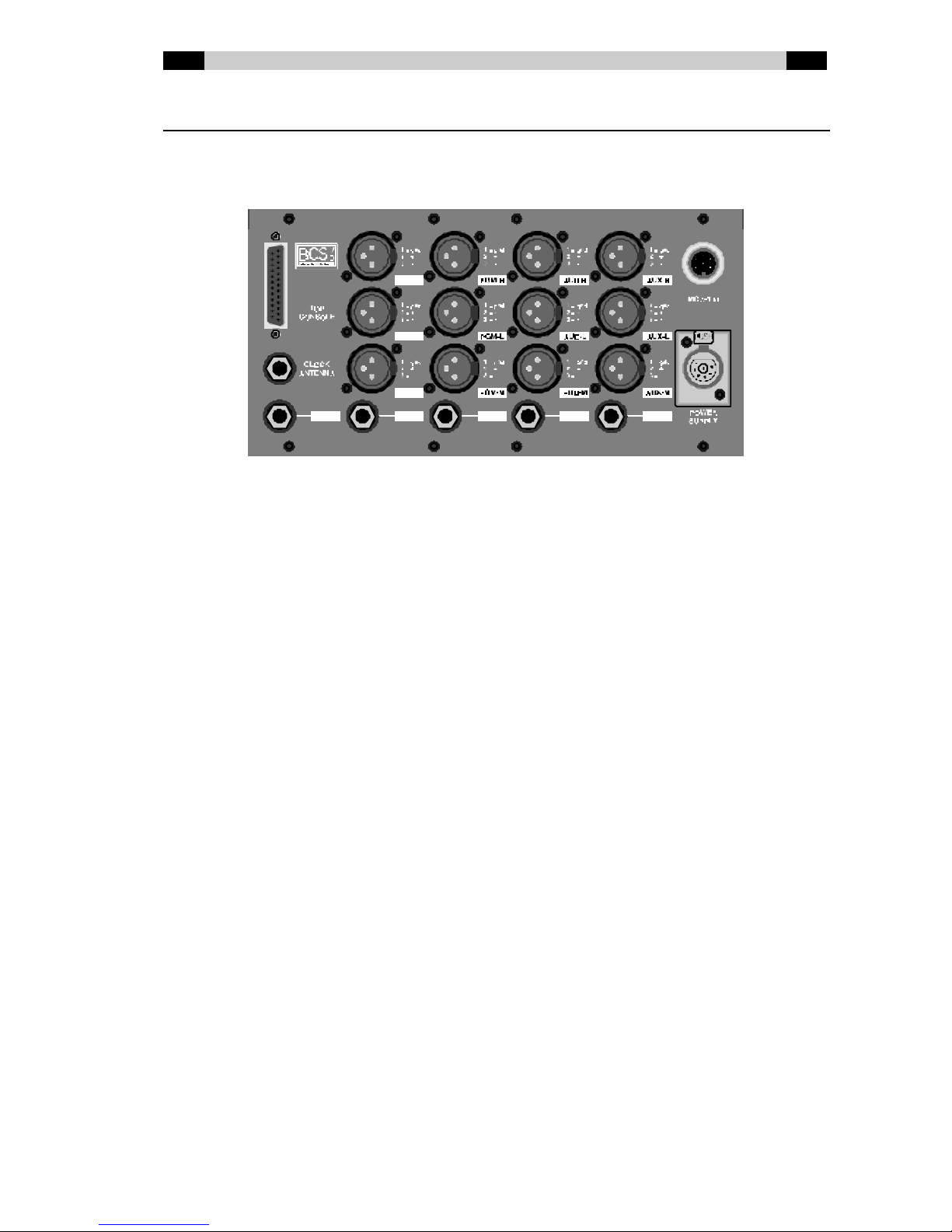
BCS70 Connector board
At the back of the script space there are, in addition to the audio outputs of the BCS70,
various other connectors. There is also space f or expansions such as extra audio outputs or
special accessories.
PGM-L/R/M ProGraM outputs (Left, Right and Mono). The PGM output is the mixer
unit's main output. These balanced outputs are electrically isolated
using transformers and are therefore suitable for carrying signals to
cable modulators, transmitters and music lines, for example.
AUD- L /R/M AUDition outputs (Left, Right and Mono). All channels for w hich the
AUD sw itch is pushed in can be heard on the AUD output. The AUD
output can, f or example, be used as decor output, as post-fader
effect send, as extra output f or a second edition of a programme, or to
quickly record a telephone interview w hilst the broadcast carries on
normally over the PGM output. The AUD control on the master module
controls the total A UD level.
AUX-L/R/M AUXiliary outputs (Lef t, Right and Mono). These outputs can be used
to connect special-effects equipment, for example. Whether a channel
can be heard on the output is dependent on the setting of the AUX-
routing sw itches. In addition, the PRE / POST jumpers can be used to
select w hether a channel must be mixed independent of or dependent
on the fader status on the AUX output. The AUX control on the master
module controls the total AUX level. Return signals from effects
equipment can be sent to the PGM output via a normal input module.
CL OCK ANT ENNA If a Dateq BCS81 clock / timer is used, the external DCF-77 aerial can
be connected here.
TOP CONSOLE 25-pin female Sub-D connector for the meter bridge.
MCA-100 Connector for Dateq MCA-100 headphone amplifiers so that more
headphones for announcers and guests can be connected - each
w ith their ow n volume control and cough / speak button.
POWER SUPPLY 7-pin XLR connector for the external pow er supply.
EN Dateq BCS70 Manual BCS70 connector board 20
BCS70 PGM-L/R/M / AUD-L/R/M / AUX-L/R/M (XLR 3p male)
Pin Function Type
1 Audio GND A-GND
2 Audio + Out
3 Audio - Out
BCS70 CLOCK ANTENNA (TRS stereo jack)
Pin Function Type
Tip Antenna + In
Ring Antenna - In
Sleeve Frame GND FRAME
BCS70 TOP CONSOLE (Sub-D 25p female)
Pin Function Type
1 Extra Meter 1 Left Out
14 Extra Meter 1 GND A-GND
2 Extra Meter 1 Right Out
15 Extra Meter 2 Left Out
3 Extra Meter 2 GND A-GND
16 Extra Meter 2 Right Out
4 Extra Meter 3 Left Out
17 Extra Meter 3 GND A-GND
5 Extra Meter 3 Right Out
18 -15V Power Supply POWER
6 Extra Meter 4 Left (2nd function: Timer Control 1) Out
19 Extra Meter 4 GND A-GND
7 Extra Meter 4 Right (2nd function: Timer Control 2) Out
20 +12V Power Supply POWER
8 +12V Power Supply POWER
21 Main Meter Left Out
9 Main Meter GND A-GND
22 Main Meter Right Out
10 GND Power Supply D-GND
23 GND Power Supply D-GND
11 DCF Antenna Signal + Out
24 DCF Antenna Signal - Out
12 BCSBus Data
25 Digital Ground POWER
13 BCSBus Data
Table of contents
Other Dateq Music Mixer manuals


