Dateq LPM 7.4 User manual

1Dateq LPM 7.4 Manual Safety instructions EN
Safety instructions
1All safety instructions, warnings and operating instructions must e read first.
2All warnings on the equipment must e heeded.
3The operating instructions must e followed.
4Keep the operating instructions for future reference.
5The equipment may never e used in the immediate vicinity of water; make sure that water
and damp cannot get into the equipment.
6The equipment may only e installed or fitted in accordance with the manufacturers
recommendations.
7The equipment must e installed or fitted such that good ventilation is not o structed in any
way.
8The equipment may never e installed in the immediate vicinity of sources of heat, such as
parts of heating units, oilers, and other equipment which generates heat (including
amplifiers).
9Connect the equipment to a power supply of the correct voltage, using only the ca les
recommended y the manufacturer, as specified in the operating instructions and/or shown on
the connection side of the equipment.
10 The equipment may only e connected to a legally approved earthed mains power supply.
11 The power ca le or power cord must e positioned such that it cannot e walked on in normal
use, and o jects which might damage the ca le or cord cannot e placed on it or against it.
Special attention must e paid to the point at which the ca le is attached to the equipment and
where the ca le is connected to the power supply.
12 Ensure that foreign o jects and liquids cannot get into the equipment.
13 The equipment must e cleaned using the method recommended y the manufacturer.
14 If the equipment is not eing used for a prolonged period, the power ca le or power cord
should e disconnected from the power supply.
15 In all cases where there is a risk, following an incident, that the equipment could e unsafe,
such as:
•if the power ca le or power cord has een damaged
•if foreign o jects or liquids (including water) have entered the equipment
•if the equipment has suffered a fall or the casing has een damaged
•if a change in the performance of the equipment is noticed
it must e checked y appropriately qualified technical staff.
16 The user may not carry out any work on the equipment other than that specified in the
operating instructions.
EN Introduction Dateq LPM 7.4 Manual 2
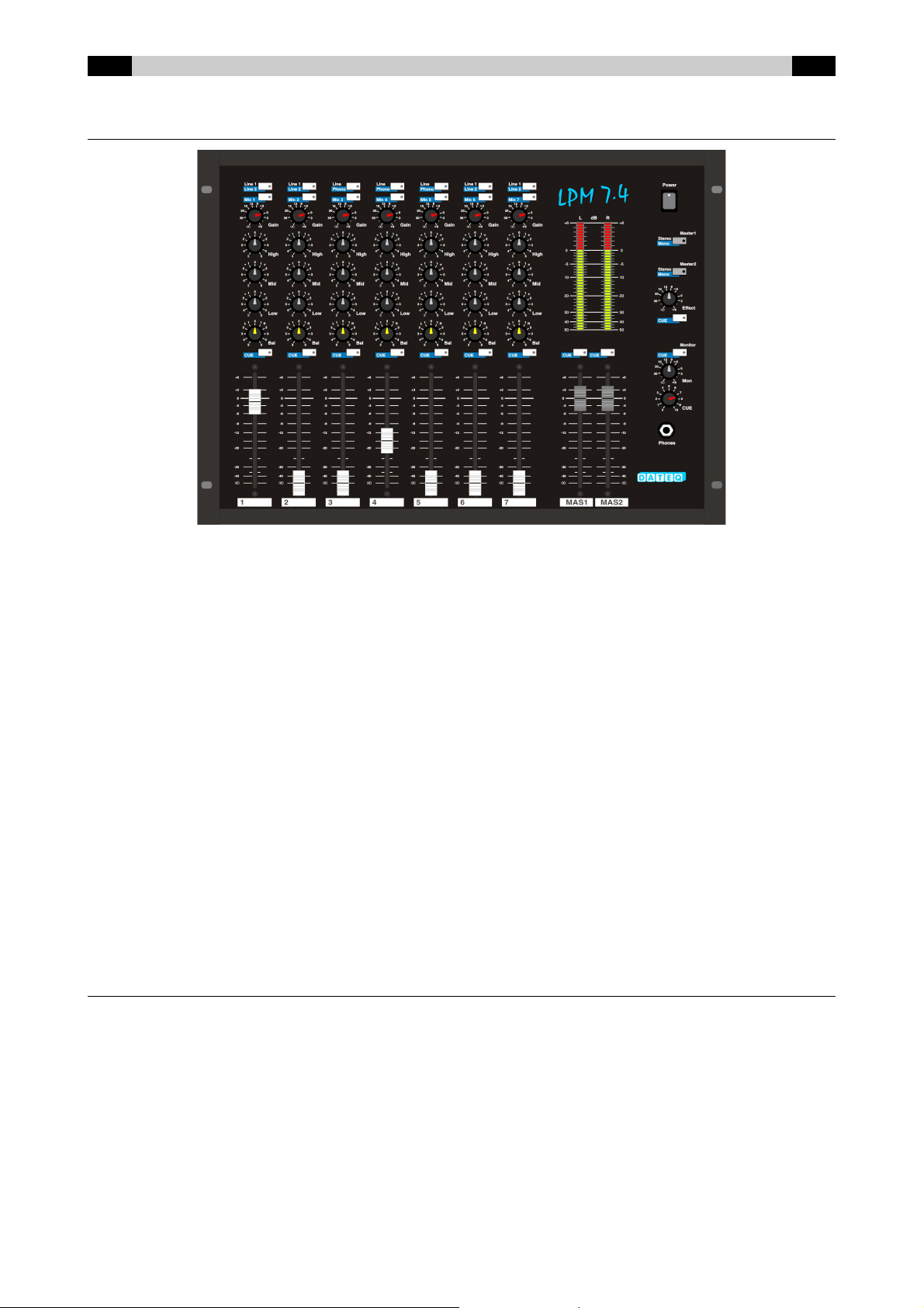
LPM 7.4: Mu tipurpose Compact Mixing Conso e
The LPM 7.4 is a very versatile, 7 channel stereo mixer with an extraordinary high quality. At least 14 stereo
signals and 7 microphones can e connected simultaneously. Herewith the LPM 7.4 is introducing a new
standard for professional audio.
Each channel can handle three different audio signals. By pressing the utton you can switch etween a
microphone or a line input. When the line-input is selected a second utton makes it possi le to switch etween
line 1 and line 2 input. However channels 3, 4 and 5 have one line and one phono-input. This means you can
have 21 audio-inputs within reach! Also there are 2 independent professional stereo Masters availa le, oth
come with a alanced output on XLR-Male connectors; as well as an un alanced output on cinch-connectors.
Another nice feature of the mixer is the stereo effect-send. Each channel can e configured to send it’s signal to
the effect-send output or not. This means that the effect-send output can also e used as a cleanfeed.
The large 2x40 segment VU-meter is switcha le etween master and PFL. All switches on the master-section
have a LED-indicator. Phantom power is availa le on each microphone channel, and can e switched on with an
internal jumper. The master has a noise-gate which can e disa led with an internal jumper.
Thanks to the internally modular setup, the extreme solid construction and y using only high-performance
components we made the LPM 7.4 an ideal partner for ‘on the road’. Of coarse the LPM 7.4 has the specific
characteristics of a ‘real DATEQ mixer’, which means years of satisfactory mixing!
Because of the universal design the LPM 7.4 has a wide area of applications. A perfect house-mix, AV-post
production, disco or a multifunctional audio installation: The LPM 7.4 can handle it...
Product support
For questions regarding the LPM 7.4, accessories and other products, please contact
Dateq Audio Techno ogies B.V.
De Paal 37
1351 JG Almere, The Nederlands
Telephone: +31 36 5472222
Fax: +31 36 5317776
E-mail: [email protected]
Internet: www.dateq.nl

3Dateq LPM 7.4 Manual Mounting EN
Mounting the LPM 7.4
The LPM 7.4 can e used as stand-alone or uilt-in (mounted). The housing fits in an opening of
448 x 335 x 107mm (W x H x D). See also the drawings elow. When mounting take into account
the protruding connectors on the ackside of the LPM 7.4.

EN Connections Dateq LPM 7.4 Manual 4
LPM 7.4 Connectorboard
The connections for all audio in- and outputs are situated at the ackside of the LPM 7.4. The
mains inlet and the fuse are also located here.
L/ R Ba anced Master 1/ Master 2 Outputs (XLR 3-pins ma e)
Pin Function Type
1 Audio GND A-GND
2 Audio + Out
3 Audio - Out
Out/ Mon/ Rec/ Effect send Stereo Outputs (Cinch fema e)
Pin Function Type
Tip Audio + Out
Shield Audio GND A-GND
Phones Output (TRS Jack 3p)
Pin Function Type
Tip Left Out
Ring Right Out
Sleeve Audio GND A-GND
Phono/ Line 1/ Line 2/ Effect Return Stereo Inputs (Cinch fema e)
Pin Function Type
Tip Audio + In
Shield Audio GND A-GND
Ba anced Mic inputs (XLR 3-pins fema e)
Pin Function Type
1 Audio GND A-GND
2 Audio + In
3 Audio - In
Cue Output (TS Mini Jack 2p)
Pin Function Type
Tip N.O. (switch contact) Out
Sleeve Common (Switch contact) Out

5Dateq LPM 7.4 Manual Mounting EN
Connections
BALANCED Electronically alanced master outputs for the left and right channel on
MASTER L / R XLR connectors for Master 1 & 2. This type of output guarantees a perfect
signal transport, even when long audio ca les are eing used. These
outputs are equipped with relays to prevent audi le ‘ lo s’ on connected
equipment when the LPM 7.4 is switched on or off.
MASTER 1 & 2 Un alanced master output on cinch-connectors. Can e used to connect
the LPM 7.4 to an amplifier or a recorder.
MON Un alanced monitor output on cinch connectors. Can e used to connect a
second amplifier with monitor speakers for the DJ or a second room.
PFL Un alanced output on cinch connectors. This output follows the pre-fader
listening. This output can e used to connect an (monitor) amplifier or
recorder.
REC Un alanced recorder output on cinch-connectors. This output is fixed-level
(independent from the master volume control).
EFFECT SEND Stereo postfader effect sends from microphone inputs. This output can
also e used as a cleanfeed output.
EFFECT RETURN Stereo effect return input. Can also e used as an extra input.
CHANNELS 1..7 Cinch connectors for all stereo channels. Channel 1, 2, 6 and 7 have two
identical line inputs. Channels 3, 4 and 5 have oth an input for turnta les
(phono) and an input for equipment like CD-players, samplers, key oards
and recorders (line). When turnta les are eing used, these must e
earthen y means of the earth-clamp.
CHANNELS 1..7 Electronically alanced microphone input on XLR connector. When used
un alanced, connect pin 1 and 3 with the shielding of the ca le. Both
channels are equipped with a secondary stereo line input.
CUE Channel 3, 4 and 5 are equipped with a remote start connector. As soon as
the fader of the concerning channel is opened, the contact etween tip and
ring of this mini jack (3,5 mm) connection is made. With this the connected
equipment can e remote started.
The remote-connection is NOT suitab e for switching mains vo tage!
FUSE Mains fuse. Dimension 5x20mm (small), 315mA slow.
MAINS Euro-style mains inlet. Before connecting the LPM 7.4for the fist time,
check if your LPM 7.4 is meant for the mains voltage in your country (la el
on the connector oard at the rear).
For a cinch-connectors:
White = Left, Red = Right.

EN Operation Dateq LPM 7.4 Manual 6
Microphone / ine channe s (1, 2, 6 and 7)
These channels are equipped with a dou le input selector which makes it possi le to easily switch
etween 2 line inputs (such as CD-players, MD recorders) and a microphone source, as well as a
Gain control, 3-way tone control, alance and pre-fader listening.
Line 1 / Line2 Input selector. When pushed line 2 is selected. The LED will
light up when the audio-level somewhere in this module is too
high. Because of the high audio level the signal can e
distorted.
MIC Input selector. When pushed (activated LED) the MIC input is
activated.
GAIN Determines the pre-adjustment of the volume for the
microphone as well as oth stereo line inputs.
HIGH High tone control.
MID Mid tone control.
LOW Low tone control.
BALANCE Adjusts the alance etween the left and right audio channel.
PFL(CUE) Switches pre-fader listening on and off indicated y a LED
inside the utton. When this function is active, the headphone
will switch to PFL and all the inputs with active PFL can e
heard even though the fader is closed. When no PFL has
een selected on any channel, the master signal can e
heard via PFL.
FADER 100 mm fader through which the volume of this channel can
e determined precisely.
Combined Turntab e-/ ine-/ microphone channe s (3, 4 and 5)
These three stereo channels have three inputs (phono for turnta les, line for equipment like CD-
players and MD-recorders and mic for a microphone input), Gain control, 3-way tone control,
alance and pre-fader listening.
PHONO / LINE Input selector. Normally the line input is selected. When
pushed the phono input is selected. The LED is an overload
indicator.
MIC Input selector. When pushed the MIC input will e activated.
GAIN Determines the pre-adjustment of the volume for the
microphone as well as oth stereo PHONO/line inputs.
7Dateq LPM 7.4 Manual Technical specifications EN
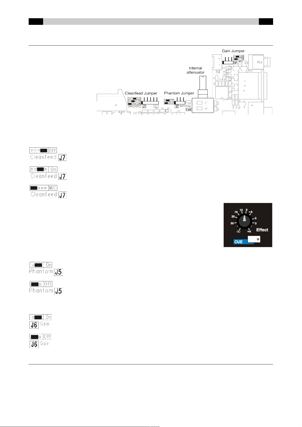
Effect sends (C eanfeed)/ Phantom and jumpers
For each channel, with
three internal jumpers, the
Effects-sends/ Cleanfeed,
the Phantom- power and
extra microphone Gain
can e selected. To adjust
these settings the mixer
has to e opened.
See the drawing.
C eanfeed. For each channel jumper J7 determines if it sends it’s signal to the effect-send
output or not. It’s also possi le to send the signal to the effect output only when the microphone
input is active.
The effect-send output is post-fader: the volume is dependent of the fader.
The output of the effect-generator can e connected to the effect-return
input. This return input can if needed also e used as an extra input.
Phantom. For each channel jumper J5 determines if phantom-power is switched on or off.
Extra Gain. For each channel jumper J6 determines if 10dB extra microphone gain is switched
on or off.
Interna attenuator
Each input-module has an internal attenuator to prevent the input-signal from eing distorted. By
default the attenuator is disa led (potentiometer turned clockwise).
When more attenuation is needed the LPM 7.4 has to e opened. The attenuation can e adjusted
for each input-module separately. Max. internal attenuation is 40dB.
Microphone Phantompower is switched off. This is the default setting.
Cleanfeed off: The channels signal is not send to the effect-send output. This is the default
setting
Cleanfeed on: The channels signal is send to the effect-send output. This can e used when
the effect-send is used as a cleanfeed. The signal of this channel is send to the telephone
hy rid. The cleanfeed of the channel to which the hy rid is connected must e set to off.
Cleanfeed MIC: The channels signal is send to the effect-send output only when the
microphone input is selected. This can e used when an effect-generator (echo etc.) is
connected to the effect-sends output.
Microphone Phantompower is switched on.
10dB extra microphone gain is switched on.
10dB extra microphone gain is switched off. This is the default setting.
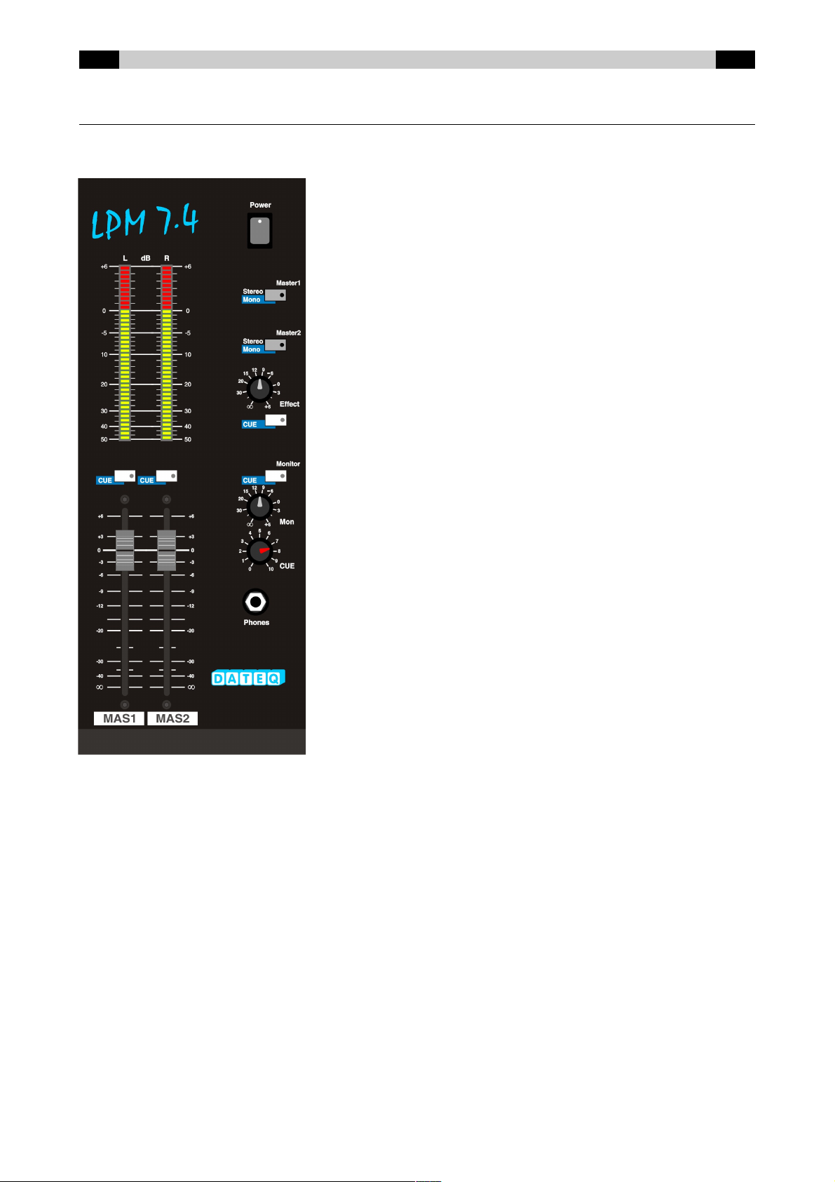
EN Operation Dateq LPM 7.4 Manual 8
Master
The master section has volume controls for the various outputs of the LPM 7.4 and a 2 x 40
segments LED- ar meter which precisely indicates the Master or PFL signal level.
POWER Mains power switch.
STEREO/MONO Switch to change the master 1 and master 2
Master 1 & 2 signal etween stereo and mono indicated y
a LED inside the utton.
EFFECT Volume control for the stereo Effect-return
input.
CUE Switch to listen to Effect-return pre-signal.
Monitor Switch to listen to the monitor post-signal,
CUE indicated y a LED inside the utton.
This function is on y active if a input
channe and effect PFL(CUE) buttons are
off.
MON Volume control for Monitor output.
CUE Volume control for the headphone output.
PHONES Stereo
headphone output.
CUE Switch to listen to post-signal of Master 1 or Master 2, indicated y a LED
(Mas 1& 2) inside the utton.
This function is on y active if a input channe and effect PFL(CUE)
buttons are off.
MAS 1 Fader which controls the output volume of Master 1 output ( oth alanced and
un alanced).

9Dateq LPM 7.4 Manual Technical specifications EN
MAS 2 Fader which controls the output volume of Master 2 output ( oth alanced and
un alanced).
Meter
2 x 40 segments LED-indication of the master or PFL level. An operational level of approximately
0dB is normal.

NL Technical specifications Dateq LPM 7.4 Manual 10
Noisegate jumper
The noisegate mutes the master-section if no input signals are present.
Jumper P27 in the mastersection determines if the noisegate is switched
on or off. See the drawing
Noisegate is switched on. This is the default setting
Noisegate is switched off.

11 Dateq LPM 7.4 Manual Operation NL
Technica specifications
MONO Inputs
MIC (channel 1..7) …...................................... XLR-3 female, electronically alanced
Signal level …........................................ -54 dB @ 600 Ohm varia le
Impedance …......................................... 3 kOhm nominal
Input noise …......................................... < -107 dB (IHF-A)
Headroom ….......................................... +20 dB
Phantom power …................................. +24 Vdc
STEREO Inputs
PHONO (Channel 3, 4 and 5) …..................... Cinch
Signal level …........................................ -42 dB @ 47 kOhm varia le
Impedance …......................................... 47 kOhm/ 25pF nominal
Input noise …......................................... < -80 dB (IHF-A)
Channel separation …............................ > 76 dB @ 1 kHz
LINE (channel 1..7) …..................................... Cinch
Signal level …........................................ 0 dB @ 600 Ohm varia le
Impedance ............................................ 10 kOhm nominal
Input noise …......................................... < -80 dB (IHF-A)
Channel separation …............................ > 80 dB @ 1 kHz
TONE CONTROL
High …................................................... 12 kHz ±12 dB, Shelving
Mid …..................................................... 1400 Hz ±12 dB, Bell
Low ….................................................... 50 Hz ±15 dB, Shelving
OUTPUTS
MASTER 1 & 2 (XLR) …................................. +6 dB alanced/ 600 Ohm/ varia le
MASTER 1 & 2 / MONITOR / PFL (Cinch) ….. 0 dB un alanced/ 600 Ohm/ varia le
REC (Cinch) …............................................... 0 dB un alanced/ 600 Ohm/ fixed
STEREO EFFECT SEND (Cinch) ….............. 0 dB un alanced/ 600 Ohm/ postfader
PHONES (6,3 mm TRS Jack) …..................... 0,3 W @ 4 Ohm/ Impedance 4..32 Ohm
FREQUENCY RESPONCE
Input to Master …........................................... 20 Hz...25 kHz -3 dB
THD+N …....................................................... 0,007 % nominal
GENERAL
POWER SUPPLY
Mains voltage ….................................... 230 VAC +/-10% @ 50 Hz
Power consumption …........................... 20 W
FADERSTART
(channel 3 t/m 5) …........................................ Maximum ratings: 48V/ 0,1A; 3,5 mm jack
SIZE AND WEIGHT
Front ….................................................. 483 x 355 mm (W x H) = 19”, 8HE
Cutout …................................................ 448 x 335 mm (W x H)
Depth …................................................. 107 mm
Weight …............................................... 6.4 kg Net.
Table of contents
Other Dateq Music Mixer manuals


