Dateq BCS25 User manual

BCS25
GEBRUIKSAANWIJZING
USER MANUAL
GEBRAUCHSANWEISUNG
MODE D’EMPLOI


EN Dateq BCS25 Manual Safetyinstructions 3
Safetyinstructions
1All safetyinstructions, warningsand operating instructionsmust be read first.
2All warningson the equipment must be heeded.
3The operating instructionsmust be followed.
4Keep the operating instructionsforfuturereference.
5The equipmentmayneverbe used inthe immediatevicinityofwater;makesurethatwater
and dampcannot get intothe equipment.
6The equipmentmayonlybe installed orfitted inaccordancewiththe manufacturers
recommendations.
7The equipmentmustbe installed orfitted suchthatgood ventilation isnotobstructed inany
way.
8The equipmentmayneverbe installed inthe immediatevicinityofsourcesofheat, suchas
partsofheating units,boilers,and otherequipmentwhichgeneratesheat(including
amplifiers).
9Connectthe equipmenttoapowersupplyofthe correctvoltage,using onlythe cables
recommended bythe manufacturer,asspecified inthe operating instructionsand/orshown
on the connection side ofthe equipment.
10 The equipment mayonlybe connected toalegallyapproved earthed mainspowersupply.
11 The powercableorpowercordmustbe positioned suchthatitcannotbe walked on in
normaluse,and objectswhichmightdamage the cableorcordcannotbe placed on itor
againstit. Specialattention mustbe paidtothe pointatwhichthe cableisattached tothe
equipment and wherethe cableisconnected tothe powersupply.
12 Ensurethat foreign objectsand liquidscannot get intothe equipment.
13 The equipment must be cleaned using the method recommended bythe manufacturer.
14 Ifthe equipmentisnotbeing used foraprolonged period,the powercableorpowercord
shouldbe disconnected fromthe powersupply.
15 Inall caseswherethereisarisk,following an incident, thatthe equipmentcouldbe unsafe,
suchas:
· ifthe powercableorpowercordhasbeen damaged
· ifforeign objectsorliquids(including water) haveentered the equipment
· ifthe equipment hassuffered afall orthe casing hasbeen damaged
· ifachange inthe performanceofthe equipment isnoticed
it must be checked byappropriatelyqualified technicalstaff.
16 The usermaynotcarryoutanyworkon the equipmentotherthan thatspecified inthe
operating instructions.

4Dateq BCS25 manual Introduction EN
Introduction
The BCS25 isspecificallydesigned forapplicationsrequiring afull-featured mixing consolewhilebeing
restricted bydimensionaland/orfinanciallimits. Post-production rooms, OBvans, on-location transmission
studiosand secondary studiosareonlyafewofthe possibleusesforthe BCS25.
The BCS25 frameissupplied with8input channels(optionalwithorwithout equalizer), the buildinpower
supplyand an extensivemastersection withLEDPPM's.
Inputmodules
The universalBCS25(E) input channelfeatures3inputs(line 1, line 2and mic), againcontrol, a3-band
equaliser(option: without)and abalancecontrol. The input signalcan be routed totwostereo mix-busses
withthe audition and programselect buttons. Thisenablesthe engineertoset up twodifferent output mixes
ortousethe consolefortwodifferent jobsrunning simultaneously.
The auxiliary 1ispre-faderand hasavolumecontrolon the module. The auxiliary 2bussendsthe signal
directlytothe mastersection, the signalmaybe selected preorpost fader.
The cue button enablespre-fade listening ofthe input source. Afader/button start featureisstandard(fader
orbutton function isset byan internaljumper). The 100 mm faderisnot inthe audiosignalpathbut only
controlsthe VCA; thispreventsanysignaldistortion and increasesreliability.
Telephonehybrid
Thereisalsoaspecialtelephone channelavailablewithintegrated analogue telephone hybrid. Thischannel
can alsobe used asaremoteforan externalhybrid. The ON/OFF buttonscan be used forthe remote
controlforthe externalhybrid.
The BCS26(E) isequipped withan intelligent electroniccircuit togenerateamix-minussignal(Dateq’s
unique TDM2). Thismakesit possibletohavemorethan one hybridinthe mixer.
BCS27 Master module
The mastersection isextremelywell equipped. It hasa40-segment LEDVU-meterwithpeakholdfunction
that can be linked toPGMout oreachofthe othersources. Inaddition the BCS27 hasamasterfaderfor
PGMout, an adjustableheadphone output formonitoring anysignal, levelcontrolsforotheroutputssuchas
aux, audition, etc.
Anysignalcan be selected tothe monitoroutputs(controlroomorheadphone)bymeansofthe switching
matrix.
The dedicated guest and the presenteroutputshaveavery practicalfeature. The engineerisabletosend a
different signalmix-than the actualPGM-toeachofthosetwooutputs. Thisenableshim/hertoperform
simpletimesaving 'post-production-during-transmission'type ofoperations!
Communication between engineer, guest and presenteriscompletelyhandled bythe console, offering
numerouspossibilities. The most interesting one isthe abilitytorout the communication signaltothe PGM
output. Thisoption hasbeen specificallyimplemented forliveon-location (OB) transmissions: it presentsa
direct and easycommunication channelwiththe studioengineerwhilenewsand commercialsarebroadcast
fromthe homebasestudio!
Product support
Ifyou haveanyquestionsconcerning the BCS25, itsaccessoriesorotherproducts, please
contact:
DateqAudioTechnologiesB.V.
DePaal37 Telephone:+31 36 54 72 222
NL-1351 JG AlmereFax:+31 36 53 17 776
The NetherlandsE-mail: info@dateq.nl
Internet: www.dateq.nl

EN Dateq BCS25 manual Installation 5
Installing the mixerunit
The BCS25 issupplied asstandardwithout acabinet orconnectorcables. It ispossibletomake
cablesforconnecting tothe Sub-D connectorsofthe variousinput and output modulesin-house.
Onlyuseconnectorswithmetalcansand shielded cablesforoptimalHF-rejection.
Installing intoacabinet
The BCS25 framefitsintoan opening of445 x395 x110 mm (WxHxD).
6Dateq BCS25 manual BCS25(E) dualline/ microphone input module EN
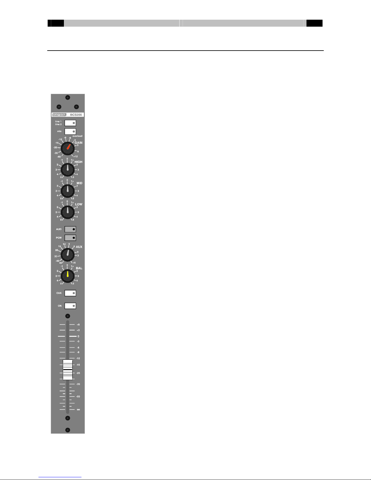
BCS25(E)dual line/ microphone input module
The BCS25(E)input moduleisavailablewithorwithout 3band equaliser. The modulecan handle
up to3different signals: 2stereo line and amono microphone. Line input 1and the microphone
input ofthismoduleareelectronicallybalanced. Line input 2isunbalanced but can be turned into
abalanced input byuseofan extrapushon balanced line-input module. The microphone input is
equipped withphantompowerwhichcan be switched off.
Line1/ Line2 Input selector. When the switchispushed (green LEDis
lighted)line 2isselected.
Mic Input selector. When the switchispushed (green LEDis
lighted)the microphone input isselected, regardless ofthe
inputselectorforline 1orline 2.
Overload The LEDinthe mic-switchlightsup red when the signal
levelanywhereinthe moduleistoo high and distortion can
occur(the limit is6dB undercliplevel).
Gain Volumepre-setting. Range: -46dB to+12dB
High High-tone control(BCS25E only).
Shelving: ±12dB @ 12kHz.
Mid Mid-tone control(BCS25E only).
Bell-curve: ±12dB @ 1.3kHz.
Low Low-tone control(BCS25E only).
Shelving: ±12dB @ 60Hz.
AUD/ PGM Bus-routing switches. When aswitchispushed (yellowLED
islighted)the signalwill be routed tothe selected output.
AUX VolumecontrolforAUX1-level. The AUX1-busispre-fader.
BAL Balance-control. The signalisplaced at the desired position
inthe stereo image.
CUE Pre-faderlistening. The LEDlightsup green when the
CUE- function isactivated. Withan internaljumperthe
master-cue function can be (dis-)activated.
ON On-off switch. It ispossibletoselect faderstart, buttonstart
oracombination ofbothwithan internaljumper. The yellow
LEDislighted when the channelison.
Fader 100mm long volumecontrol. Depending on ajumper-
setting the signalon the AUX2-busispre-orpost-fader.

EN Dateq BCS25 manual BCS25(E) dualline/ microphone input module 7
BCS25(E)connectorboard
DB25-Fconnector
All connectionsaremade on thisconnector. The function ofthe variouspinscan be
found inthe table.
BCS25(E)Audioand ControlInput/ Output(Sub-D 25-pinsfemale)
Pin Function Type
1Channelon lamp(15V/ 1Wmax.)(Line 1)Out
14 Common externalon lamp/ externalCUE (Line 1)D-GND
2ExternalCUE (Line 1)In
15 ExternalmuteIn
3RemoteStart; 15V/ 10mA (Line 1)Out
16 GND/ Common externalmuteGND
4RemoteStop; 15V/ 10 mA (Line 1)Out
17 Line 2Audioleft -*In*
5Line 2Audioright -*In*
18 Line 2Audioleft +*In*
6Line 2Audioright +*In*
19 AudioGND A-GND
7AudioGND A-GND
20 Microphone Audio-In
8Microphone Audio+In
21 AudioGND A-GND
9AudioGND A-GND
22 Line 2Audioleft +In
10 Line 2Audioright +In
23 Line 1Audioleft -In
11 Line 1Audioright -In
24 Line 1Audioleft +In
12 Line 1Audioright +In
25 AudioGND A-GND
13 FrameGND Frame
*: Theseinputsareavailablewhen the optionalbalanced input module, orthe RIAA-
correction amplifierareinserted. The line 2unbalanced inputsaretobe discarded.
When aRIAA-correction amplifierismounted usepins6and 18 forthe signal. Pins5and
17 areinternallyconnected tothe ground.
8Dateq BCS25 manual BCS25(E) dualline/ microphone input module EN
Phantompower
Non-dynamicallymicrophonesusuallyneed an externalpowersupplyforitsbuilt inpre-amplifier.
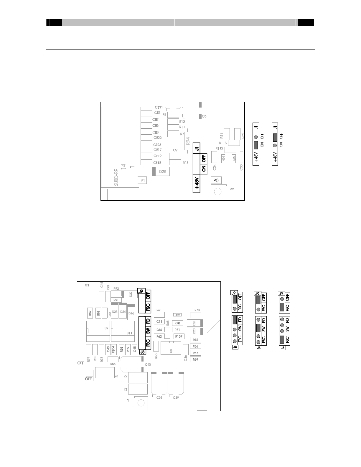
Ifthispowerhastobe supplied bythe BCS25, placejumperJ1inthe ‘ON’ position. +48Vdcwill
be supplied tobothsignalwiresrelated tothe cablesshielding.
JumperJ1issituated on the left side ofthe bussconnector. The factorydefault setting forthis
jumperis‘OFF’. See picturebelow:
Dynamicallymicrophonesdon’t need aphantompowersupply. When the correct cablesareused
it will not damage the microphone when the phantompowersupplyisturned on. Soit isnot really
dangeroustoturnthe phantompoweron forall typesofmicrophones.
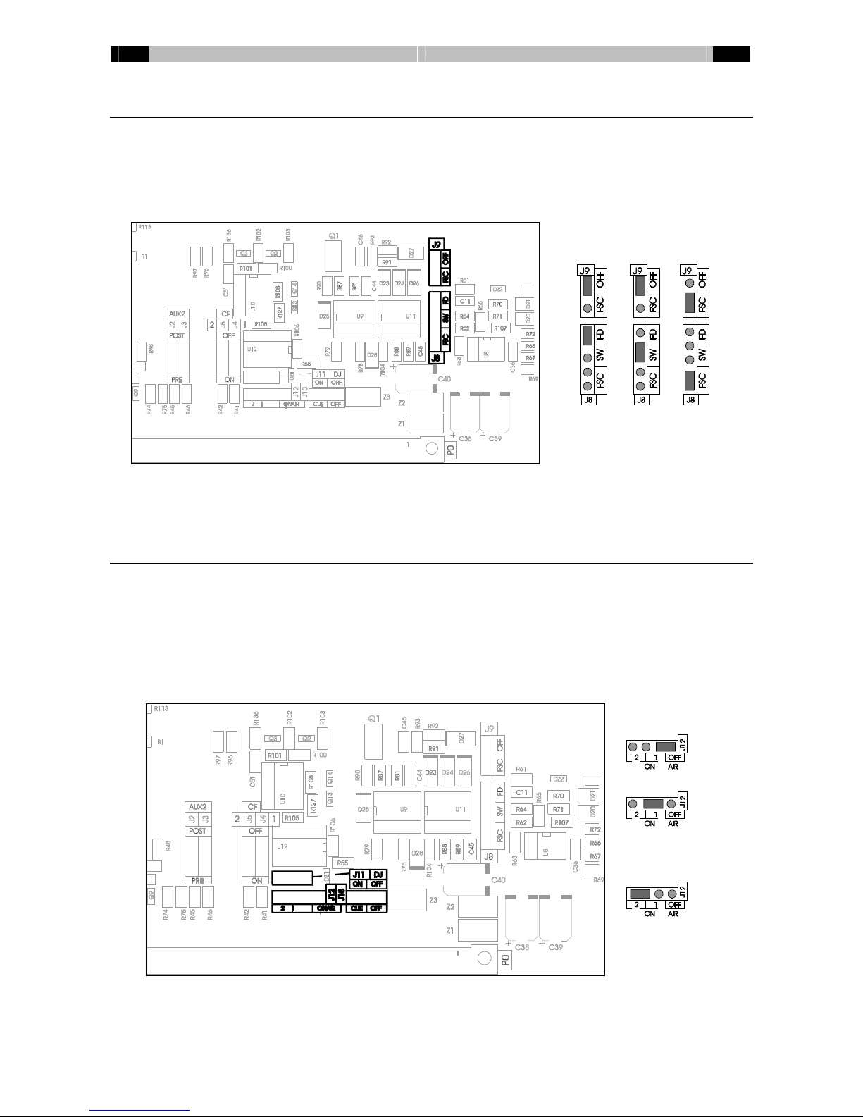
Faderstart/ buttonstart
The BCS25(E)moduleisabletoremotestart connected equipment byfaderstart, buttonstart ora
combination ofthesetwooptions. Bychanging jumpersyou easilyselect one ofthesesettings.
The jumpersforremotestart settingscan be found at the mainPCB abovethe bussconnector
(jumperJ8and J9, see drawing).
JumpersJ8and J9select the type ofoperation. It ispossibletochoosebetween faderstart (figure
1), buttonstart (figure2)orthe fader-switchcombinaton (figure3).
Fig. 1
Fig. 3
Fig. 2
EN Dateq BCS25 manual BCS25(E) dualline/ microphone input module 9
FADER, SWITCHCOMBINATION
When the fader-switchcombination isselected the connected equipment can be started intwo
different ways:
1.Pushing the startbutton when the faderisclosed. The connected equipment will start assoon
asthe faderisopened.
2.Opening the fader. The connected equipment will start assoon asthe button ispressed
Tostart the connected equipment 2conditionshavetobe fulfilled. When just one ofthe
conditionsisfulfilled the LEDinthe button will light up dimmed toindicatethat the equipment will
be started assoon asthe faderisopened/ the ONispressed.
The equipment will stop assoon asthe button ispressed orthe faderisclosed.
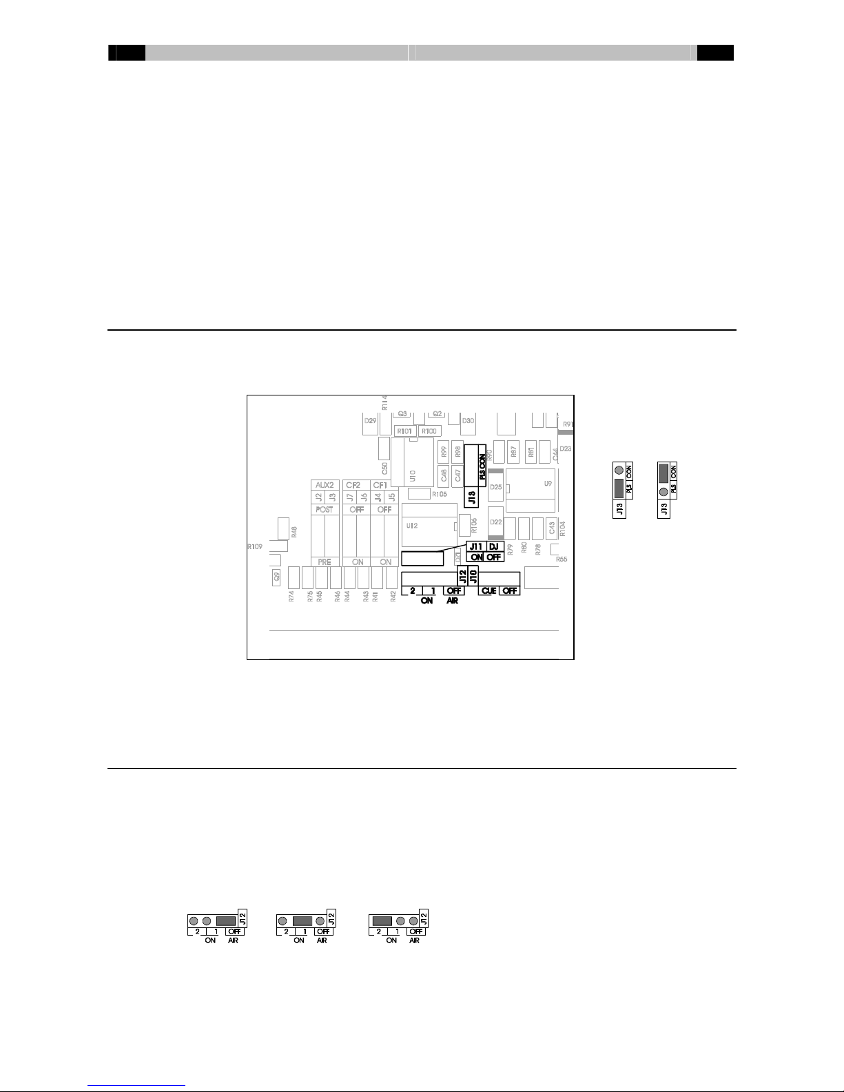
Remote control output
The BCS25(E)modulecan generateacontinuesorpulsed start/stop signal. JumperJ13 at the
mainPCB (abovethe bussconnectorinthe middle)selectsbetween acontinue-orpulsesignalat
the remoteoutput.
Inthe pulseposition the remoteoutputswill generateapulseof100msec. When the continues
mode isselected the on-output will provide ahigh levelsignalwhen the channelisswitched on
and alowlevelsignalassoon asthe channelisswitched off. The remoteoutputsonlyworkwhen
line input 1isselected.
On-airchannels
The BCS25 hastwoon-air groups. Thismakesit possibletodrivean indicatortoindicatethat the
microphonesareopened. The output will be activated when one ormorechannelsthat belong to
the on-air group areopened.
WithjumperJ12 achannelisconfigured ason-air 1oron-air 2channel. When achannelis
configured ason-air 1the studiooutput will be muted when the channelisactive. The on-air 1
output on the masteralsowill be activated. A channelconfigured ason-air 2will not mutethe
studio, but onlyactivatethe on-air 2output on the master.
Fig. 4
Fig. 5

10 Dateq BCS25 manual BCS25(E) dualline/ microphone input module EN
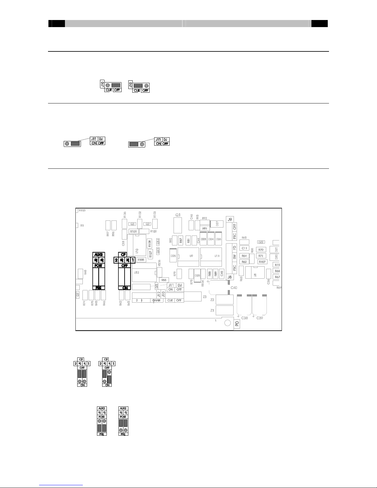
Master-cue
Eachchannelcan activatethe master-cue function. When the cue-button ispressed the master
moduleautomaticallyselectsthe CUE-busasinput. Thisfunction can be activated withJ10.
DJ-Mode
Inaself-support configuration the controlroomhastobe muted when the microphone isopened.
The announcerhastouseaheadphone, sothat acousticalfeedback isimpossible.
When jumperJ11 isset toDJ, the controlroomwill be muted when the channelisactivated, all
CUE-functionswill be turned off and the mastermodulewill select programoraudition,
depending on the routing switches.
Cleanfeeds en Auxiliarybus
The BCS25(E)modulecontains2(mono)busoutputswhichcan be used tocreateareturnsignal
to, forexample, an ISDN codec. The signalat thesebussesispost-fader. At eachindividual
channelofthe consolecan be selected iftheybelong toone orbothofthe cleanfeedsbysetting
jumpersJ4…J7inthe right position.
Inthe examplebelowthe signalofthischannelissend tocleanfeed bus1only.
Beside the cleanfeedsthe BCS25(E)modulehas2auxiliarybusses. The first auxiliaryisalways
pre-fader. Auxiliary2can be switched between pre-and postfaderbyjumperJ2and J3.
EN Dateq BCS25 manual BCS26(E) telephone input module 11
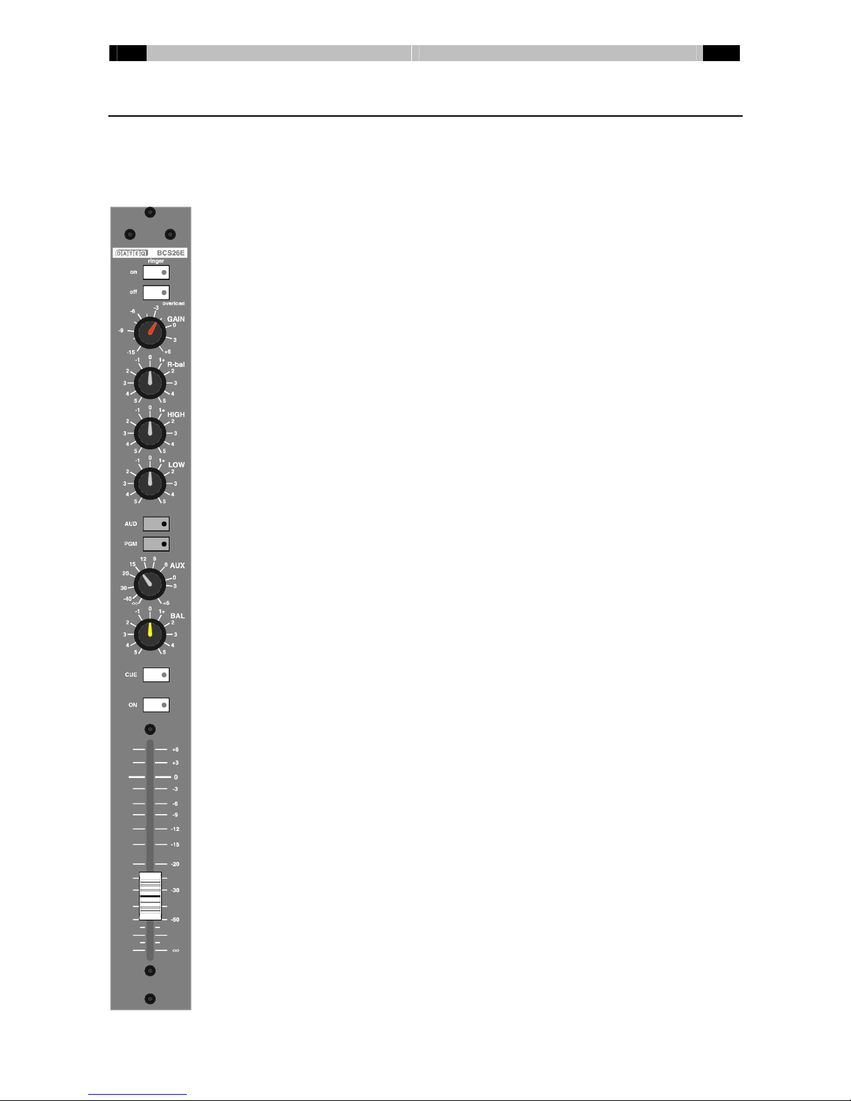
BCS26(E)telephone input module
The BCS26(E)telephone input moduleisavailablewithorwithout 2band equaliser. The module
isequipped withabuilt-inanalogue telephone hybrid. Telephone linescan be directlyconnected
tothischannel. Besidesthe built inhybridan externalhybridortalk-showsystemcan be
connected. Inthat case, the BCS26(E)channeloperatesasremotecontrolonly.
On/Off Switchesthe (external) hybridon oroff. The green LEDwill
light up at an incoming ringersignal.
Overload The LEDinthe off-switchlightsup red when the signallevel
anywhereinthe moduleistoo high and distortion can occur
(the limit is6dB undercliplevel).
Gain Volumepre-setting. Range: -15dB to+6dB
R-bal Compensation forthe resistivepart ofthe line-impedance.
High High-tone control(BCS26E only).
Shelving: ±12dB @ 3.5kHz.
Low Low-tone control(BCS26E only).
Shelving: ±12dB @ 600Hz.
AUD/ PGM Bus-routing switches. When aswitchispushed (yellowLED
islighted)the signalwill be routed tothe selected output.
AUX VolumecontrolforAUX1-level. The AUX1-busispre-fader.
BAL Balance-control. The signalisplaced at the desired position
inthe stereo image.
CUE Pre-faderlistening. The LEDlightsup green when the CUE-
function isactivated. Withan internaljumperthe master-cue
function can be (dis-)activated.
ON On-off switch. It ispossibletoselect faderstart, buttonstart
oracombination ofbothwithan internaljumper. The yellow
LEDislighted when the channelison.
Fader 100mm long volumecontrol. Depending on ajumper-setting
the signalon the AUX2-busispre,-orpost-fader.

12 Dateq BCS25 manual BCS26(E) telephone input module EN
BCS26(E)connectorboard
DB25-Fconnector
All connectionsaremade on thisconnector. The function ofthe variouspinscan be
found inthe table.
BCS26(E)Audioand ControlInput/ Output(Sub-D 25-pinsfemale)
Pin Function Type
1Phone: A (telephone line)Out
14 Phone: B (telephone line)Out
2--
15 --
3Line: A (telephone line)In
16 Line: B (telephone line)In
4--
17 --
5Off-hook(On); 15V/ 10 mAOut
18 GND GND
6Ring; 15V/ 10 mAOut
19 --
7Remotehybridout; Optocoupleroutput +Out
20 Common -GND
8Remotehybridon; Optocoupleroutput +Out
21 --
9--
22 Receiveaudio+In
10 Receiveaudio-In
23 AudioGND A-GND
11 AudioGND A-GND
24 Send audio+Out
12 Send audio-Out
25 AudioGND A-GND
13 FrameGND Frame
EN Dateq BCS25 manual BCS26(E) telephone input module 13
Faderstart/ buttonstart
The BCS26(E)moduleisabletoremotestart connected equipment byfaderstart, buttonstart ora
combination ofthesetwooptions. Bychanging jumpersyou easilyselect one ofthesesettings.
The jumpersforremotestart settingscan be found at the mainPCB abovethe bussconnector
(jumperJ8and J9, see drawing).
JumpersJ8and J9select the type ofoperation. It ispossibletochoosebetween faderstart (figure
6), buttonstart (figure7)orthe fader-switchcombinaton (figure8).
On-airchannels
The BCS25 hastwoon-air groups. Thismakesit possibletodrivean indicatorwhen the
microphonesareopened. The output will be activated when one ormorechannelsthat belong to
the on-air group areopened.
WithjumperJ12 achannelisconfigured ason-air 1oron-air 2channel. When achannelis
configured ason-air 1the studiooutput will be muted when the channelisactive. The on-air 1
output on the masteralsowill be activated. A channelconfigured ason-air 2will not mutethe
studio, but onlyactivatethe on-air 2output on the master.
Fig. 7
Fig. 8
Fig. 6
14 Dateq BCS25 manual BCS26(E) telephone input module EN
Master-cue
Eachchannelcan activatethe master-cue function. When the cue-button ispressed the master
moduleautomaticallyselectsthe CUE-busasinput. Thisfunction can be activated withJ10.
DJ-Mode
When jumperJ11 isset toDJ, the controlroomwill be muted when the channelisactivated, all
CUE-functionswill be turned off and the mastermodulewill select programoraudition,
depending on the routing switches.
Cleanfeeds en Auxiliarybus
The BCS26(E)modulecontains2(mono)busoutputswhichcan be used tocreateareturnsignal
to, forexample, an ISDN codec. The signalat thesebussesispost-fader. At eachindividual
channelofthe consolecan be selected iftheybelong toone orbothofthe cleanfeedsbysetting
jumpersJ4and J5inthe right position.
The first exampleshowsachannelthat doesn’t belong toacleanfeed. The second example
belongstocleanfeed one and not tocleanfeed two.
The BCS25 had twoauxiliarybusses. The first busisalways pre-fader; the second buscan be
configured tobe pre,-orpost fader. Thisisdone withJ2ad J3.
EN Dateq BCS25 manual BCS26(E) telephone input module 15
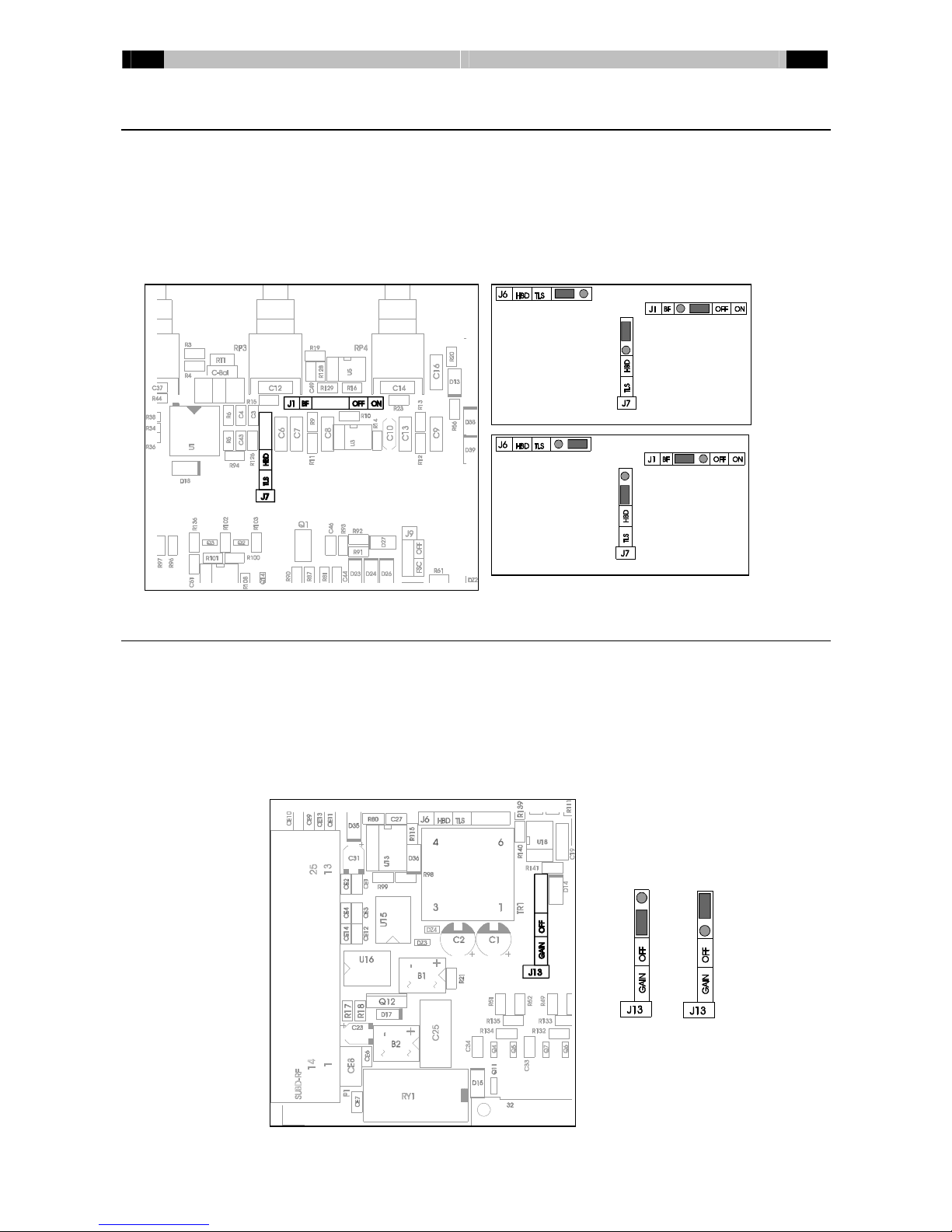
Internal orexternal hybrid
The BCS26(E)modulehandlesincoming telephone callsoverthe built-inhybrid, but isalsoable
toremotecontrolan external(digital) hybridortalkshowsystem.
WithjumperJ6, J7and J1it’spossibletoselect the type ofoperation. JumperJ6and J7areused
toswitchbetween the internalorexternalhybrid, J1switchesthe bandpass filteron oroff. When
ahybridwithbuilt inband pass filterisconnected J1shouldbe placed inthe OFF position.
(The drawing belowonlyshowsJ1and J7. J6can be found abovethe transformer; see the
autogaindrawing at the bottomofthispage).
Autogain
The BCS26(E)isequipped withaspecialfeaturethat reducesthe signalfromthe hybridby6dB
when audioissent fromthe mixertothe hybrid. Thismeansthat the callerisdimmed by6dB
when the announcerinthe studiospeaks. Thisfeatureimprovesthe side tone reduction with6dB,
socreating the best possiblespeechintelligibility. The consequenceofthisauto-gainfeatureis
that when the callerand announceraretalking at the sametime(“doubletalk”), the announcerin
the studiowill slightlydrownthe voiceofthe caller.
Thisfunction can be disabled withjumperJ13. Inthe first examplethe autogainfunction is
enabled.
Fig. 9: Internalhybrid, bandpass filter on
Fig. 10: Externalhybrid, bandpass filter off

16 Dateq BCS25 manual BCS26(E) telephone input module EN
TDM²
The hybridautomaticallygetsthe correct N-1returnfromthe CUE, PGMorAUD bus. Thisisthe
so-called TripleDynamicMix-Minussystem, shortened toTDM2. Sincethe BCS26 generatesthe
N-1signalitself, separatecleanfeedsarenot necessary. The numberofBCS26 moduleswhich
can be used at the sametimeisthereforetheoreticallyunlimited. Inpractice, the numberof
telephone lineswhichcan be used at the sametimeislimited bythe qualityofthe telephone
hybridsbeing used.
IfAUD isselected aswell asPGM, the returnfromthe PGMbushaspriorityoverthe returnfrom
the AUD bus.
CUE hasthe highest prioritywhen the channelisoff. Assoon asCUE isselected on aBCS26
module, the hybridgetsthe returnfromthe CUE bus.

EN Dateq BCS25 manual BCS27 Mastermodule 17
BCS27 Master-module
The BCS27 master-modulehasamicroprocessorthat handlesthe audio-matrix. Thismatrix
routesthe audiooutputs. The second function ofthe microprocessoriscontrolling the VU-meter.
TB-MIC Connectorforthe Talk-Back microphone.
Meter Sourceselectorforthe VU-meter. The meter
switchesbetween PGMofcontrolroom.
AUX1 Volumecontrolforthe auxiliary1output.
AUX2 Volumecontrolforthe auxiliary2output.
AUD Volumecontrolforthe audition output.
Air...Cue Selection ofthe signalon the controlroomand the
CUE output. The activeselection isindicated witha
yellowLEDunderthe button.
Mute The LEDlightsup REDifthe controlroomoutput is
automaticallyswitched off.
CR Volumecontrolforthe controlroomoutput.
VU-meter The VU-meterindicatesthe levelofthe selected
source. The upperLED’swill blinkwhen the levelin
the mastermoduleistoo high (the limit is6dB under
cliplevel).
Fader 100mm long volumecontrolforthe programsignal.

18 Dateq BCS25 manual BCS27 Mastermodule EN
PGM/TBK Sourceselectorforthe guest output. Switchesbetween program
and talkback.
GST Volumecontrolforthe guest headphone output.
ANN Volumecontrolforthe announcerheadphone output.
STUD Volumecontrolforthe studiooutput.
AIR...CR Sourceselectorforthe studio, announcerand guest outputs.
CUE Volumecontrolforthe CUE (headphone)output.
PGM...ALL Talkbuttons. Thesebuttonsenablethe talkback function tothe
selected source. The ALL button talks toGuest, announcer,
CUE and CFwhen thisfunction isenabled.
CUE Headphonesoutput.
Special functions
· The studiooutput can be toggled tofollowthe programsignalorthe selection
indicated on the sourceselector. Togglebetween thesefunctionsbypressing
the AIRand the CR button simultaneously.
Bydefault the studiooutput will followthe programsignal.
· It ispossibletoenableordisablethe ‘talktoprogram’ function. Thisisdone by
simultaneouslypressing the AIRand talk-to-programbuttons. When the talkto
programfunction isactivated the controlroomwill be muted.
Bydefault thisfunction isdisabled.
· The guest output can be used asan externalcommunication channelfor
exampletoasecond studio. Thisfunction can be enabled bysimultaneously
pressing the AIRand talk-to-guest buttons. The guest output will be muted.
The onlysignalon the guest output isthe talk-signal.
Bydefault thisfunction isdisabled.
· It ispossibletoenableordisablethe ‘talktocleanfeed’function. Thisisdone
bysimultaneouslypressing the AIRand talk-to-cue buttons. When the talk-to-
cue button ispressed the talkback signalwill be routed tothe cue and the
cleanfeed buss.
Bydefault thisfunction isdisabled.
· The DJ-mode hasthree settings. Thesesettingscan be selected bypressing
the AIRand PGMsimultaneously.
1. The masterautomaticallyswitchestoPGMorAUD, depending on the
selected buss on the microphone input,
2. The masterautomaticallyswitchestoAIR,
3. DJ-mode disabled. The sourcewill not change.
EN Dateq BCS25 manual BCS27 Mastermodule 19
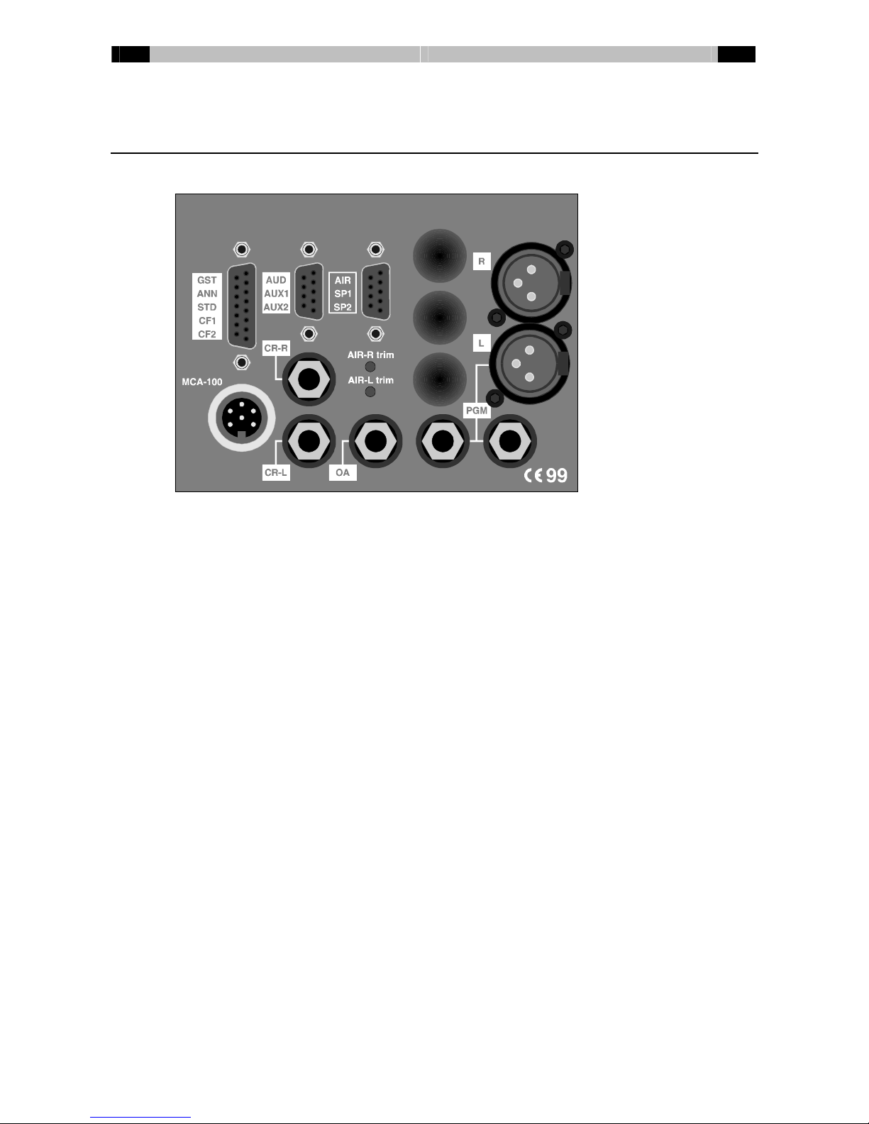
BCS27 connectorboard
The BCS27 connectorboardhasthe connectorsforthe in,-and outputs. Therearethree spares
forextrajack-connectors.
GST/ ANN/ STD/ CF1/ CF2
15-pinsfemalesub-D connectorwiththe signalsforthe guest, announcer, studioand two
cleanfeeds. The guest and announceroutputshaveheadphonesdrivers. The studioand
cleanfeed outputsareat line-level.
AUD/ AUX1/ AUX2
9-pinsfemalesub-D connector. Onthisconnectorthe outputsforthe audition, auxiliary1
and auxiliary2can be found.
AIR/ SP1/ SP2
9-pinsfemalesub-D connectortowhichthe air, spare1and spare2signalscan be
connected. The levelofthe air-input can be adjusted withtwotrimmers; one forthe left
signalleveland one forthe right signallevel.
MCA-100
ConnectorforDateq’sMCA-100 headphone amplifierssothat moreheadphonesfor
announcersand guestscan be connected -eachwiththeir ownvolumecontroland
cough/ speakbutton.
CR-R &CR-L
Balanced controlroomoutputs.
OA
On-air outputs. On-air indicators, suchasDateq’sOA1, can be connected.
PGM
XLR-3male: Balanced programoutputs.
Jack: Twounbalanced stereo programoutputs.

20 Dateq BCS25 manual BCS27 Mastermodule EN
BCS25 GST/ ANN/ STD/ CF1/ CF2(DB15-Fconnector)
Pin Function Type
1Announcerheadphone right out Out
9AudioGND A-GND
2Announcerheadphone left outOut
10 AudioGND A-GND
3Guest headphone right outOut
11 AudioGND A-GND
4Guest headphone left outOut
12 AudioGND A-GND
5StudiorightOut
13 AudioGND A-GND
6StudioleftOut
14 AudioGND A-GND
7Cleanfeed 2Out
15 AudioGND A-GND
8Cleanfeed 1Out
BCS25 AUD/ AUX1/ AUX2 (DB9-Fconnector)
Pin Function Type
1Audition rightOut
6AudioGND A-GND
2Audition leftOut
7Aux1rightOut
3AudioGND A-GND
8Aux1leftOut
4Aux2rightOut
9AudioGND A-GND
5Aux2leftOut
BCS25 AIR/ SP1/ SP2(DB9-Fconnector)
Pin Function Type
1Air rightIn
6AudioGND A-GND
2Air leftIn
7Spare2rightIn
3AudioGND A-GND
8Spare2leftIn
4Spare1rightIn
9AudioGND A-GND
5Spare1leftIn
Table of contents
Other Dateq Music Mixer manuals


