Dato CRMPL 201 User manual

AUTO BODY COLLISION REPAIR SYSTEM
Operation Manual
CRMPL 201

CONTENT
ⅠIntroduction............................................................................................................................................. 1
1.Trademark.................................................................................................................... 2
2.General presentation of standard components......................................................2
3. Accessory assembly..................................................................................................2
ⅡLoading and Unloading................................................................................................................. 4
1. Attentions during transportation...................................................................... 4
2. Loading and Unloading........................................................................................4
ⅢInstallation............................................................................................................................................... 4
1. Space requirement................................................................................................ 4
2. Placement of equipment..................................................................................... 4
3. Installation of tower chains............................................................................... 4
4. Installation & Debugging of Pulling Towers............................................... 5
5. Installation of tool cart and placement of tools........................................5
ⅣLoading and unloading vehicle ...............................................................................................6
1. Use of
accessories ……………………………………………………………………6
2. Loading vehicle operation.................................................................................. 6
3. Unloading vehicle operation............................................................................. 7
ⅤVehicle anchoring.............................................................................................................................. 7
1. Introduction of anchoring system ................................................................... 7
2. Anchoring the vehicle on platform..................................................................8
ⅥPulling and straightening operation ................................................................................... 8
1. Movement and anchoring of the pulling tower..........................................8
2. Pulling operation.................................................................................................... 9
3. Use of the steel wire sling................................................................................. 9
ⅦOperating regulations of LAUNCH body alignment ............................................ 9
ⅧMaintenance.........................................................................................................................................10
ⅨSafety precautions.......................................................................................................................... 11
1. Platform lifting and descending..................................................................... 11
2. Vehicle anchoring.................................................................................................11
TH E EN D ........................................................................................................................................................... 12

1
FOREWORD
Acco mpany ing the dev elopm ent of aut omo tiv e desi gn and techno log ies, new
mate rials are widel y applied on auto bodi es. Tod ay, most vehicl es are made of
high -ca rb on ste el ins tea d of so ft or medium -carbon steel, which mak e s a gr eat
diffe re nce in repa ir.
Afte r co llision , al l direction pul l mu st be ap pli ed to auto body. To prot ect
passen ger s at the se co nd collisio n, DO NOT heat aut o body, this may chang e
meta l struc tur e and redu ce metal hardnes s.
Powered by hydraul ic pressur e and variou s tool s and accessorie s, the LAU NC H
Body Repai r Syst em can rest ore the dam a ged auto body as original as pos sible by
mult ipo int pu lli ng. The measu ri ng sy stem is des ig ned to en s ure the accur acy of
pull ing and to rest ore the origin al dim ensio ns.
This manual is to illustrate the installation, training, operation and
maintenance of CRMPL 201.There is details on the application of
basic equipment and accessories, the clamping of vehicles and the
measurement by measuring system. To enable the operators to
master repairing skills, a number of pictures are attached.
Duri ng th e installati on and opera tion of the syst em, fol low the safe ty ca utions in
the manual to preve nt injury. DO NOT exceed the rate d loa d and pressu re to av oid
damag e to system or inj ury.
CRMPL 201 Bo dy Repai r Syst em aims to help rest ore the dam a ged vehicles
rapidly and accurat ely as well as to creat e conv enie nt and comfort able
envi ron ment for opera tors.
This manual is the instruction for CRMPL 201 body repair systems.
The photos may change from time to time, please refer to the real
object. LAUNCH Company is responsible for final explanation.
ⅠIntroduction
CRMPL 201 BODY RE PAIR SYSTE M is the high -e nd sy stem of LA UNC H
Company. The platfo rm is wel ded of 14# I-STEEL, which is with hig h stren gth
and goo d rigi dity; tower and plat form are unit y des ign, tower moves around the
plat f orm rail fr ee at 360 degr ees ; pla tfo rm ve r tica l hoist des ig n, five wo rking
heig hts se lec table. Impo rted hydrau lic sy stem s features long li fe , lo w
malf unctio n rat e; the wh ole sy stem is powere d by one electric pum p and
controlle d by remote contr ol, eas y and con ve nien t oper ation. More impor te d
allo y ste el clam ps features lo ng life and hi gh stren gth; to ol cart and acces sori es
are eas y to use; hi gh acc uracy 3D mecha nical me asuring syste m with global au to
data is ve ry conv enie nt to us e. CRMPL 201 ca n fit smal l, medium and big sized
vehicles.

2
1.TRADEMARK
On receiving the frame machine check the parts of the identification nameplate that has to
correspond to that shown below.
Table 1:
LAUNCH
MODEL:
CRMPL 201
YEAR OF PRODUCTION
20150110
FRAME LENGTH
5600mm
FRAME WIDTH
2112mm
FRAME HEIGHT
300-1080mm
POST MAX. TENSION
95KN
POST WORKING RANGE
360 Degree
PNEUMATIC PRESSURE RANGE
0.8MPa
MAX. LIFTING WEIGHT
3500Kg
2.GENERAL PRESENTATION OF STANDARD COMPONENTS
The frame machine model CRMPL 201 standard type is composed as follows:
Table 2:
NO
MAIN PART
PART
QUAN.
UNIT
1
FRAME ASSEMBLY
Frame
1
Set
Pulling tower
2
Set
3.5M Main chain
2
Piece
Chain with hook
2
Piece
Loading ramp
2
Piece
2
CLAMPS/SUPPORT ASSEMBLY
Main clamps
4
Set
Wheel bracket
2
Set
Air hydraulic pump
2
Set
Air hydraulic cylinder
2
Set
Hydraulic hose with connector
2
Piece
3
ACCESSORY ASSEMBLY
Pulling tools
19
Piece
Wheel dolly
2
Piece
Tools board
1
Set
Dolly for tools board
1
Set
Hand winch
1
set
3. ACCESSORY ASSEMBLY
1) Pulling tools assembly.
It consists in the tools board, dolly for tools board and 17 pieces of pulling tools. The different
pulling tools are used according to the different distortion. The pulling tools may be used
singly; also several tools are used together. The use method is not changeless, but various
according to the model of accident vehicle, the degree of damage, the habit of operators. It

3
may develop the subjectivity of operators and supply more convenience. These are 17
pieces of pulling tools。
ATTENTION: When operation, do not exceed the Max Load capacity as far as the data in
table 3 are concerned. The manufacturer has the right to change the quantity and model of
pulling tools.
2) Dolly for wheel
The dolly for wheel is used to move the accident vehicle whose wheel is break.
ⅡLoading and Unloading
Platfor m Len gth
5600 mm
Platfor m width
211 2mm
Workin g heigh t
0-380 -108 0mm
Capacity
3500 KG
1. Attentions during transportation
a) The truck loading capac ity mus t be min.3 .5 tons.
b) Duri ng trans porta tion , the equ ipment is not all owe d to cont act tr uck floor,
there must be woo dbloc k und er it.
c) The equipme nt must be fixed durin g transpo rt ation.
d) Th e mov able com ponen ts (for example towe r) must be fixed dur ing
transpo rt ation .
e) Neve r pla ce sha rp items or objects on the upper surf ace of the equi pme nt to
prote ct the pain t.
f) Do not load the equipme nt with inflammabl es or corr osives .
g) Prevent equipme nt from rain or getting wet .
2. Loading and Unloading
Use eit h er cra ne or forkli ft to load and un loa d the equip m ent. Wh en usi ng cra ne,
the ste el wires pos iti ons must be evenly dep loyed aroun d the platform to get
bala nce; whe n using fork lift , the lif ti ng capab ility must be at leas t 5 tons, and
plac e the forks to maxim um distance . The lengt h of forks shou ld be at leas t 1.6
mete rs and use exten sions if len gth is not enough. The forks mu st be inse rt ed
unde r the platf orm at bala ncing positio ns width wa ys.
ⅢInstallation
1. Space requirement
Min .4 m ×7m s mo o th ce me nt gr ou nd is req ui red eq ui pp ed.
2. Placement of equipment
Move the pla tform to prope r pos it ion, lea ve enoug h spac e bet wee n the plat f orm
edge s an d wall s to all ow tower movem ent and repair acc ess.
3. Installation of tower chains
Inse rt the chain end without hook throu gh the co llar pulley upwa rd ly, and then
throu gh th e tower hea d. Loc k it by tower head lock (Fig ure 3-1 , 3-2)

4
Figur e3-1 Figure3-2
4. Installation & Debugging of Pulling Towers
A Li ft pu lli ng towers with jack to make slide whee l clos ed with bench tr ack , the
dist ance bet we en the upper whe el and bench oute r is 2mm. (F igu re 3-3)
B Inst all the hook pl ate of pulling tower, and lock the scre ws (F igu re 3-4)
Figure3-3 Figure3-4
5. Installation of tool cart and placement of tools
Use M8×10(4pc), M8 ×35( 4pc) bol ts to fix tool boar d, bas e and tria ngl e
co nne ct ing pl ate toge the r. Inse rt hooks on both sizes of to ol boards. Put cla mps
and ac ce ssories on the boar d.( Figu r e 3-5 )
Figure3-5
5
ⅣLoading and unloading vehicle
1. Use of the accessories
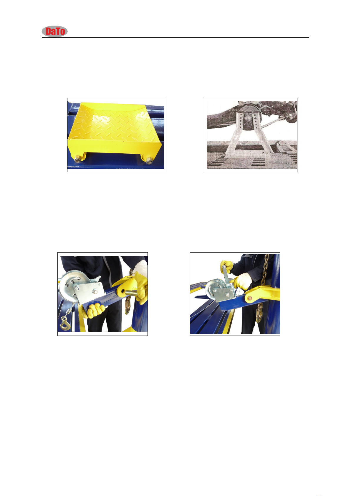
a) De ad ca r dol ly- ---W hen one or more whee ls ar e dea d durin g a collis ion. Put the
doll y unde r the dead wh eels, thi s work sh ould be don e with a jack . An d then
drive the car ont o the benc h wit h the possib le equ ipmen t. (Figu re 4-1 )
Figur e4-1 Figur e4-2
Wheel dolly insta lla tion of eac h mode l act s same.
b) Wheel st and ---- Adjust the ex te nsion bolt of th e wheel stand. Find th e righ t on
the whe el stand, and get the two bolt s on the wheel boss into holes, then
fast en the m with the nuts (Fi gure 4-2)
c) Ins tal lation and use of Winch
Tak e out the axle of the pul ling tower, ( Figure 4-3) inst all the winch , then open
the swit chin g then crank, loose the steel wire. ( Figure 4-4 )
Figur e 4-3 Figur e 4-4
2. Loading vehicle operation
A. Un lock th e anch ori ng bolt s on the pl atf orm (Figu re 5-1 ). Power on the
Electricity pump, and switch the switch bar to “PLATFORM” position (Figur e 5-2). Position
the loadi ng ramp to its righ t place (Figu re 5-3 ), then drive the vehicle on, or pull it
on wi th retractor. Operate the con trol handl e UP to lif t the plat f orm.
(Fig ure 5-4) W hen the pla tform ris es to the suitab le hei ght , stop lif ti ng and press
the decline button LOCK lowe r the pla tf orm corre spond ingl y to get the plat form
lock ed mecha nically. (Figu re5 -5 )
Caution:
1. Joint the power line before use the 220V electric pump. Please notice the rotating forward and
reverse of the electric machine.
2. Open the back door of the electric cabinet before use it. To find an oil filler point, filling 46#
anti-wear hydraulic oil –such as Shell, Mobil.

6
Figure 5-1 Figure 5-2 Figure 5-3
Figure 5-4 Figur e 5-5
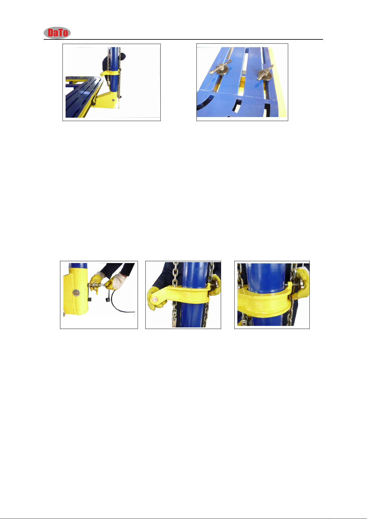
3. Unloading vehicle operation
Firstly lift the platf orm for some spa ce to rel ease the safet y lock. Pow er the
pneu m atic contro l swi tch compresse d air(≥0.5Mpa ) through the IN end , (Figu re
6-1) press the pneum atic contro l switc h DOW N (Fig ure 6-2 ) to release the safet y
lock (Figur e 6- 3) The n press the dec line button to get the pl atf orm dow n to the
base stead ily. Release the pneu m atic contro l but ton LOCK to reset the safety
lock (Fi gur e 6-4).F ina ll y drive the vehi cl e off the pla tform.
Figure 6-1 Figure 6-2

7
Figur e 6-3 Figure 6-4
ⅤVehicle anchoring
1. Introduction of anchoring system
The ve hicl e an chorin g sy stem of CRMPL 201 is a set of T- top clam ps, whic h
is un iversal amon g all LAU NCH body repai r syst ems and su ita ble for mos t
of unib ody vehicles with an edge at the bot tom . This kind of clam p feat ures
great joggling pow er and strong fastness , which can suppo rt large pul lin g
power and as sure s the safety of pul lin g work.( Figur e 6-1)
Figur e 6-1 Figure 6-2
2. Anchoring the vehicle on platform
Firs tly put the fo ur clamps on to the plat f orm under the anc horin g points of
the vehic le, and adjust the clamps to the level heigh t. Raise the vehi cle to
a certain heig ht with a rol ling sc is sor jack or other lifti ng tools. Release the
bolt s of the cla mps, and pos iti on the m at the ancho ri ng poi nts one by one,
and low er the vehi cle to get the vehic le edge into the clamp top, tighte n the
bolt s of the clamps. Fin all y anc hor the clam p s ont o the platfor m with th e
special bol ts and anchoring panels. Cla mp for CR MPL 201 (Fi gure 6- 2)
ⅥPulling and straightening operation
Operation of the pulling tower
1. Movement and anchoring of the pulling tower
Loos en the tower bolt s and pull out the tow er pins, mo ve the pull ing tower
around the platform slowly (F igur e 7-1).W hen the pulling tower is at its
right pos ition, anchor it with the tower bolt sol idl y and insert the towe r pin
(Figu re 7-2).
8
Figur e 7-1 Figure 7-2
NOTE: Wh ile doing th e pul li n g work, plea se mak e sur e that the platform is at
its lo we st heig ht , or else, no pull i ng work is allow ed.
2. Pul li ng ope ra tion
Connect the tw o qui ck coupl ers on th e platfor m and tower (Fig ure7 -3 ),
positio n the tower co lla r to a suit abl e hei ght (F igure 7-4),s elect the ri ght
pull ing tool and an c hor it to the ve hicl e bo dy, wh ere need s pulling, then join
to th e pul lin g chain, adjust the length and dir ecti on of the chain to get ev ery
section into a line, and ass ure the othe r end of the cha in is lo cked on the
tower ra m. St art the oil pum p, whe n the chain is getting tightening, loosen s
the towe r collar, and the n conti nue to do pul lin g (Figure 7-5).
Figur e 7-3 Figur e 7-4 Figur e 7-5
NOTE: Pleas e do not pul li ng arrisways or cross ly, to pr ot ect the outsi d e
guide way and tow er rol lers fro m bei n g dam age d.
3. Use of the steel wire sling
When usin g the pulling tool s, you should prev ent the pulling ring from
dise ngagi ng and bounc ing wit h a stee l wire slin g. Fa ste n one end of the sling
to th e ring, and buc kle the other end to the vehi cle or pla tform.
ⅦOperating regulations of LAUNCH body alignment
system
A . Be sure to wear work clothes and gloves when you are in the
working area, no baboosh or high-heel shoes.

9
B. Inspection before operation:
a. Bef ore oper ating the machine, please clean the working area and keep all
the sundr ie s awa y from the plat f orm, tidy the air and oil hos es to protect
them from being crus hed.
b. Che ck the air and oil rout e to make sur e all the adapt ers are conne cted
well and the re is no dam age of the hoses.
c. Replace the hydr aul ic oil of the pump aft er 3 workin g months, and do it
every 3000 wo rk ing hour s. Some quality hydr auli c oils ar e rec ommen ded,
such as G-46#, Gulf- 46, Mobil -30 , BP-32, Shel l-32, Esso-32, Calt ex- 32.
Remembe r to eli mi nat e the deposits in the oil box when repla cing oil.
d. In spect the anc h oring bolts of the tower rol le r, an d make sure the bolt s
are tig hte ned well .
C. Regulations of driving on & off
a. Nobody is all owed to stand by the plat form dur ing the plat form up & down ;
and some instruc tions are need ed when driving on & off.
b. Be sure to an chor th e pu lli ng towers duri ng the pl atf orm up & do wn.
c. When the vehi cle is on the platfor m, be sure to lock the shift an d also
bloc k the whee ls with some wood.
d. Be sure that the sa fe ty leg s are fully locked by the blo cks at the base.
D. Regulations of anchoring the vehicle
a. In spect the clam p top and clean up the sm ears and dusts.
b. Be sure that ther e is no distorti on and cracks on the clamp.
c. Ti ghten the ancho ri ng bolts of the clamps bef ore pul lin g.
E. Regulations of the measuring system
a. Be careful to tak e the measurin g rods , and pr ote ct them from dist ortion or
damage.
b. Read the me asuring va lue hori zon tall y to red uce the toleranc e.
c. Ple ase put the rods back to the box.
d. Do not tig hte n the scre w too tight .
F. Regulations of pulling operation
a. Before pulling, inspec t the chain, pulli ng tools and pull ing ring , and ma ke
sure ther e are no cr ack s or dam a ges on them .
b. Tight en the tower anc horin g bol ts dur ing pul lin g, and do not pos iti on the
tower co ll ar abov e the red preca utio n lin e.
c. Be sure of loo senin g the tow er colla r.
d. Do no t exce ed the rate d loa d of the pulli ng tools duri ng pulli ng.
e. Do not tou ch the pull ing tool s and chain during pulli ng.
f. No one is al lowed to st and behind the pullin g tower during pull ing .
g. Anc horing the veh icl e at the opp osite side with cha in when doing the great
pull ing work .
h. When there are any probl ems with the par ts or hydr aul ic syste m, please
repair them as sti pula ted by the sup plier s.
ⅧMaintenance
1) Maintenance of the hydraulic system
A. Kee p a clean ly en vir onmen t for the hy dra ulic system.

10
B. Keep the hydrau lic part s away from dus ts, chi ppi ngs and cau s ti c liquids, and
prote ct th e oil box and gau ge.
C. Inspect the hydrau lic circui t, and make sure there is no oil leak.
D. Ch eck the oil qua nti ty in the oil tank perio dically. Replac e the hy draulic oil of
the pum p afte r 3 work in g month s, Some qualit y hydrau lic oil are
recommend ed, sucha sG-46 #,G ulf- 46, Mob il-30,B P-32, S hell -32 ,E sso-32,C altex-
32.Re membe r to elim inate the depos it s in the oil box when repla cing oil .
E. Prot ect the oil adapt ors with a rubber cov er, wh en they are uncon nected.
F. When there ar e any prob lems with pum p or cy linde rs , please do repa ir th em
as stipul ated.
2) Maintenance of pulling tools
A. Keep the jog gli ng par ts of the pulling tools clean fr om dus ts and smears.
B. Do not knock the pul ling tools and cha in dur ing pulli ng.
C. Do not exce ed the rated load of the pulli ng tools duri ng pulli ng.
D. Prot ect the pulling tools fro m caus tic liqui ds.
E. Clean the pulli ng tools with some dry clo th after finish ing pulling work.
3) Maintenance of measuring system
A. Be care ful to take the measu rin g rods, and prot ect them fr om disto rt ion or
damage.
B. Prot ect the pulling tools from cau stic liq uids.
C. Do not tig hte n the sc re w too tight .
D. Please put the rods bac k to the box.
4) Maintenan ce of the plat fo rm and access ories
A. Keep the pla tform clean and dry fr om dus ts and ca usti c liquids .
B. Do not knock the pla tform .
C. Prot ect the measuring guide way and clean the dus ts timely.
D. Lubr ica te the tow er ro lle rs , col lar rol ler, wheel leg and movabl e leg
periodi call y
E. Insp ect the bolts and spring clips of the towe r roller and legs regu larly,
tight en or replac e them if ther e is any probl em.
ⅨSafety precautions
1. Platform lifting and descending
a) If there is no flow control valve on the end of liftin g cy lind er, it is prohibit ed
to op en pressure disch arg e val ve at full speed .
b) Wh en lif ting or desce ndin g pla tform , the tow ers must be fixed at the ot her
end to preven t sli de.
c) Wh en lifting or des c ending pla tform , put th e car ’s shif t at par kin g posit ion ,
bloc k the wh eels with triangle wood; no person is allo wed to stand behi nd
the car.
d) Keep the pla tform and surr oundings cle ar, oil hose and air hose mus t be well
prote cted .
e) Mak e sure the mov able stand is fixed aft er platf orm is lif te d.

11
2. Vehicle anchoring
a) Check and clear cla m p jaws befor e anch ori ng vehic le.
b) Chec k the clam p to see if there is any def ormation or crack.
c) The lo ck ing bol ts must be full y screwed .
3. Pulling operat ion
a) Check tower rol ling bea ring anc hor ing bolt bef ore moving tower.
b) Move tower s by pushi ng inste ad of pul ling .
c) Towe r fixin g bo lts must be fully screwed before pull ing.
d) Check and clear cla m p jaws befor e anch ori ng vehic le.
e) DO NOT twist the ch ain ; Make sure the cha in is lock ed on the top of the ra m.
f) Turn and loose the tower collar hand whee l. Do not screw it.
g) Ne ver ham mer or beat the chains or clamps when pul ling. It is recommen ded
to us e prot ectio n carpet over the cha ins.
h) Pay att enti on to the pull ing tools to prevent over pul ling or tear.
i) Do NOT over pull the accessorie s.
j) No irrel evant persons or untrain ed persons by LAUNCH are all owed to
oper ate the pum p.

12
THE END
The main procedures of collision repair include: bend and twist
adjustment, replacement of seriously damaged welded steel plates,
Operators must make a detailed repair plan according to the condition of
each damaged vehicle beforehand. The main steps are as follow:
1. Analyze the damage and make a repair plan;
2. Disassemble the relevant decoration parts and mechanical parts;
3. Locate the damaged vehicle on the platform and decide to repair or to
replace the damaged parts according to actual condition;
4. Pulling operation;
5. Rustproof process;
6. Painting;
7. Re-assemble all parts;
8. Test-drive the vehicle.
The collision influences vehicles greatly. The auto body design request
the front and the rear sections to be easily damaged, which will form
collision energy absorbing structure and firm passenger section. Learn
as much as possible about the collision and make a detailed plan
according to actual measurement.
This manual introduces the installation; test and operation of CRMPL
201.There are also detailed introduction on collision analysis and
adjustment. For each damaged vehicle, analyze the actual condition and
make a detailed repair plan instead of following the illustrations in this
manual.
Table of contents


