The COM S2 User manual

1
Owner’s Manual
Premium UTV Communication System

2
Welcome to the COMplete Radio InterCOM
COMmunication family. We thank you for your
purchase with care the unit should give you good
service.
Please read these instructions carefully, by doing so
you will get full use of the unit
Email if you have any questions or concerns that this
manual does not address.
www.
utvCOM
.com
info@
utvCOM
.com

3
InterCOM
IMPORTANT NOTE:
There are no serviceable parts in this unit.
Damage may be caused if you open the case. These units do not have
an internal battery.
Main Features
•
Automatic Volume Control - to prevent excessive volume in the
headset
•
Noise Reduction - to eliminate amplification of background
noise
•
Noise cancelling microphones - for improved sound
reproduction
•
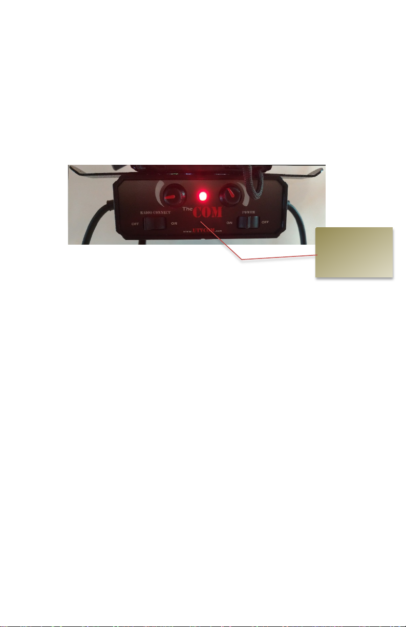
2 way radio connection with speaker cut-off switch, mic level
control and PTT socket
•
Audio input for music (CD/mp3) or auxiliary source (GPS etc.).
•
Mobile phone connection with level selection to suit a wide
range of phones
•
Audio output socket to tape/mp3 recorder (to record pace
notes) or connection to video camera. Switchable
options to customize your
COM
to your requirements
Intercom or
Amplifier

4
Headsets
•
Full face and open face headset options.
•
Aviator headsets (without helmet), for crew
COM
munication on road sections or when preparing
pace notes.
Introduction
The
COM
is an in
ter
COM
system designed to allow communication
between both the driver, passengers and other cars through the Push To
Talk (PTT) and allow connection to a variety of equipment for off-road
recreation or racing.
The
COM
has engineered this model to provide greater audio quality
and provide a better experience for the user by eliminating background
engine noise and preventing excessive sound levels in the headsets.
Additionally, greater connectivity has been provided to accommodate
the increasing use of mobile phones and other audio devices in the car.
Thank you for purchasing this product, with care the unit should
give you good service. Please read these instructions carefully, by
doing so you will get full use of the unit and save a great deal of
frustration!

5
Fitting the headset parts to your helmet
Speakers
–
Carefully fit the speakers inside the helmet so that they align
exactly with your ear canal. The Velcro should stick to the helmet lining
or if not, you can glue or stitch the Velcro loop fabric in place. (See
helmet headset install video @ https://utvcom.com/thecom-tips-ticks/ )
Microphone (Full face helmets)
–
Place the mic in the mouth guard
as close to your lips as possible. The mic may be fastened by glue or
stitching the Velcro loop fabric in place.
Microphone (Practice headsets & boom mics)
–
Practice headset
and boom mics should be adjusted so that the mic is in line with your lips
and no more than half an inch from your lips for the greatest audio
performance. Note the further the mic is from your lips the more distant
your voice will be and the less amplified it will be to the co-drivers.
Microphone (Open face) –
Shape the microphone arm base to the
shape of the helmet. Make sure that there are no gaps between the
microphone arm base and the helmet. Set the boom and mic up inside the
helmet so that the mic will be in-line with your lips. Note where the zip
tie clips will secure the boom to the inside hard surface of the helmet.
Wipe and clean the inside surface with a cloth to remove any dust and
make sure that the helmet is clean. Fasten the microphone arm base in
position on the helmet using the adhesive pad provided. The microphone
MUST NOT be more than ½ inch from your lips. For right hand drive
cars make sure that the driver’s microphone is fastened to the left side of

6
the helmet and the co-driver’s microphone is fastened to the right. (vice
versa for left hand drive cars).
All headsets IMPORTANT –
The white clip should be fastened to the
side of the helmet to alleviate strain on the cables. If not used, premature
failure of the headset may occur.

7
Installing
The
COM
Amplifier Unit –
Mount The
COM
bracket between the driver and co-
driver on the rear roll bar, position so that cables and the headsets do not
obstruct operation of the vehicle and are kept clear of the steering wheel.
The unit should be fastened to a roll bar with the provided clamps or in
the case of an in-dash unit it should be mounted securely in the dash.
Connect the 12-volt power cord to a correct 12-volt power port. If you
decide to hardwire the unit it is recommended that both the hot and
ground wires be connected directly to the battery terminals to avoid
interference and the cables should NOT be run together with other vehicle
wiring. The hot wire should be fused with a 10 amp in-line fuse when
snipping the S2 power receptacle. In-dash units do not require an
additional in-line fuse.
Avoid proximity to pedals and other moving parts and use cable
grommets to avoid chaffing where cables pass through the bulkhead. You
must fit the fuse in the positive lead, directly after the positive terminal
.

8
Using your COM
Radio
Radio Volume &
press and hold to
power down or
power up
Toggle between
Memory & Channel
mode (for simple
channel driven radio
Channel
Selector or
press to
enter radio
menu
Exit from menu
and Toggle bands
Toggle
between FM
radio and Ham
(walkie-talkie)
radio
Current band indicator
(similar to AM and FM on
your car radio
25 watt radio
Hand mic dust
plug

9
Power switch –
The right-hand switch on
The
COM
switches
the unit on and off, push to the left to switch on.
Volume control –
The volume control on the Radio affects the
overall volume to Th
e
COM
users. It is very sensitive and should
be adjusted from minimum volume while someone else is
broadcasting. For best results we suggest setting the radio to the
local weather channel (see below common channels for weather
frequency) and slowly turn the radio volume clockwise until
desired volume is clear. Sometimes backing the volume on the
radio slightly will give a clearer communication from outside
signals. After the radio is set, fine tune the volume with the
individual volume controls found on the Int
er
COM
(
see below)
and the aviator headsets if purchased.
Individual Intercom Volume controls –
The driver’s side
volume control affects the overall volume to the driver’s side
headset plug and the co-driver (passenger) side volume control
affects the overall volume to the co-driver’s side headset plug.
Set these controls individually to give a comfortable level.
Radio connect switch
disconnects the radio from the
intercom. If not receiving
transmissions make sure this
is on.
Intercom power switch
(right is off / left is on) Red
light led will come on when
powered
Left Volume Right Volume
LED power
indicator

10
Noise
reduction dial
3.5 mm PTT
Optional Antenna
manager
In-line noise filter
Rear jumper wire (is a
directional wire) Input
radio in radio &
intercom into
amplifier. PTT to PTT
Optional Bluetooth
power adapter

11
Automatic Volume Control
– The
COM
is equipped with
an automatic volume control or “limiter”. This will raise normal
speech levels to a constant level and prevent excessive volume in
the headset. This can be disabled if not required by switching off
the DIP switch marked LIMITER on the rear panel.
Rear Jumper Wire –
There is one jumper wire on T
he
COM
.
The rear jumper wire must be plugged in to communicate with
the intercom (amplifier).
If you would like to use the radio hand mic and the radio
independently of the intercom, you will need to unplug the rear
jumper wire from the radio and remove the front dust plug from
the front then plug in the hand mic. Once the rear jumper wire is
removed the internal speaker on the radio will automatically turn
on. Note that the volume on the radio will need to be increased
when operating the radio independently of the intercom. You
will need to re-connect the rear jumper wires before The
COM
will properly function as one unit.
The rear jumper wire is directional. Make sure the tip of the
jumper wire marked as “Radio” is plugged into the 25-watt
radio 3.5mm port that shows a headset symbol (the other port
is marked “Data” and is plugged with a dust protector from
the factory to prevent plugging the jumper wire in the wrong

12
port). The other end of the jumper wire is marked “Intercom”
and should only be plugged into the intercom. TheCOM will not
work properly unless the jumper wire is properly installed.
Noise Reduction -
The
COM
is equipped with a noise
reduction system that will eliminate amplification of
background engine noise. The threshold at which this
discriminates between background noise and your voice can be
adjusted with the control on the rear panel marked NOISE
REDUCTION. Rotating this adjuster clockwise will require a
higher speech level to activate the microphone. Noise
reduction can be disabled if not required by switching off the
DIP switch marked “1” on the rear panel to the down position.
The noise reduction switch is switched off from the factory. To
turn it on switch the DIP switch marked “1” up then adjust the
control dial to the desired setting.
Switch on Forehead of The COM assembly –
The toggle
switch on the front is for the lights. “I” is for the single cargo
light in the back simply rock the switch to the “I” position. “II”
is for the dual cabin lights in the front and “O” is for off. To turn
off the lights rock the switch to the center position.

13
Transmit level setting
- Make a call to another radio and
confirm that your voice can be heard in the remote radio. The
level of your voice can be adjusted by inserting a screwdriver in
the slot marked RADIO TX LEVEL, this can be reduced if your
voice is received at a particularly high or distorted level or it can
be increased if you voice is faint. (Note turning the TX up to
high may cause distortion on the receiving end of your
transmission).
9-watt LED
cabin lights
Switch to “I” for cargo
light
Switch to “II” for dual
cabin lights
“O” or in the center of the
toggle switch is lights off

14
Audio output –
The 3.5mm socket marked AUDIO OUT on the
rear of the amplifier can be connected to a tape/mp3 recorder. The
speech of both crew members can then be recorded along with any
auxiliary input.
Audio input
–The 3.5mm socket marked AUDIO IN on the
rear of the amplifier can be connected to auxiliary equipment
such as GPS
Mobile phone connection / Level setting
– The 3.5mm
jack socket on the back of the amplifier marked “TEL” can be
connected to your mobile phone. (Suitable leads and adapters
can be purchased from Th
e
COM
or your local dealer). Adjust the
amplifier for normal operating levels and then make a call with
your phone and set the volume on the phone to give the required
level in the headsets. The small “DIP” switch marked
“Telephone RX” on the rear panel can be set to reduce or
increase the received level if required. A similar switch marked
“Telephone TX” can be used to set the microphone level into the
mobile phone. This can be switched ON to reduce the mic level
if excessive background noise or distortion is heard at the remote
phone and should be left OFF if your voice is too faint.
Push to talk (PTT) button for
transmitting outside the
vehicle

15
Frequency coordination –
The radio has been programmed
with numerous frequencies (channels). Channels 1-7, 15-22 are
GMRS frequencies and are commonly used across the nation.
We ask you to be courteous and use good practices before
selecting a channel for your area. Listen first to see if someone
is using that channel. Do not interrupt or use offensive
language. For more local information seek out your local
frequency coordinator.
http://www.sbe.org/sections/freq_local.php
DPI switches
(Down is off switch up
for on)
3.5mm ports. Dust plugs are
installed in “Audio in” & “Audio
Out” ports and will need to be
removed prior to use
TX adjust (is
factory adjusted to
¼ turn clock wise
from bottom)

16
Channel
Band
Frequency
Name
1
UHF
462.5625
GMRS1
2
UHF
462.5875
GMRS2
3
UHF
462.6125
GMRS3
4
UHF
462.6375
GMRS4
5
UHF
462.6625
GMRS5
6
UHF
462.6875
GMRS6
7
UHF
462.7125
GMRS7
8
9
10
11
12
13
14
15
UHF
462.5500
GMRS15
16
UHF
462.5750
GMRS16
17
UHF
462.6000
GMRS17
18
UHF
462.6250
GMRS18
19
UHF
462.6500
GMRS19
20
UHF
462.6750
GMRS20
21
UHF
462.7000
GMRS21
22
UHF
462.7250
GMRS22
23
VHF
444.1000
WB7HAM
24
VHF
162.4000
NOAA weather
25
VHF
162.4250
NOAA weather
26
VHF
162.4500
NOAA weather
27
VHF
162.4750
NOAA weather
28
VHF
162.5000
NOAA weather
29
VHF
162.5250
NOAA weather
30
VHF
162.5500
NOAA weather

17
Channel
Band
Frequency
Name
31
VHF
146.5050
VHF31
32
VHF
146.5100
VHF32
33
VHF
146.5150
VHF33
34
VHF
146.5300
VHF34
35
VHF
146.5350
VHF35
36
VHF
146.5400
VHF36
37
VHF
146.5450
VHF37
38
VHF
146.5500
VHF38
39
VHF
146.5550
VHF39
40
VHF
146.5600
VHF40
41
VHF
146.5650
VHF41
42
VHF
146.5700
VHF42
43
VHF
146.5750
VHF43
44
VHF
146.5800
VHF44
45
VHF
147.5200
VHF45
46
VHF
147.5250
VHF46
47
VHF
147.5300
VHF47
48
VHF
147.5350
VHF48
49
VHF
147.5400
VHF49
50
VHF
147.5450
VHF50
51
VHF
147.5500
VHF51
52
VHF
147.5550
VHF52
53
VHF
147.5600
VHF53
54
VHF
147.5650
VHF54
55
VHF
147.5700
VHF55
56
VHF
147.5750
VHF56
57
VHF
147.5800
VHF57
58
VHF
147.5850
VHF58
59
VHF
147.5900
VHF59
60
VHF
147.5950
VHF60

18
Channel
Band
Frequency
Name
61
VHF
147.6000
VHF61
62
VHF
147.6050
VHF62
63
VHF
147.6100
VHF63
64
VHF
147.6150
VHF64
65
VHF
147.6200
VHF65
66
VHF
147.6250
VHF66
67
VHF
147.6300
VHF67
68
VHF
147.6350
VHF68
69
VHF
147.6400
VHF69
70
VHF
147.6450
VHF70
71
VHF
147.6500
VHF71
72
VHF
147.6550
VHF72
73
VHF
147.6600
VHF73
74
VHF
147.6650
VHF74
75
VHF
147.6700
VHF75
76
VHF
147.6750
VHF76
77
VHF
147.6800
VHF77
78
VHF
147.6850
VHF78
79
VHF
147.6900
VHF79
80
VHF
147.6950
VHF80
81
VHF
147.7000
VHF81
82
UHF
445.9250
UHF82
83
UHF
445.9500
UHF83
84
UHF
445.9750
UHF84
85
UHF
446.0000
UHF85
86
UHF
446.0250
UHF86
87
UHF
446.0500
UHF87
88
UHF
446.0750
UHF88
89
UHF
446.1000
UHF89
90
UHF
446.1250
UHF90

19
Channel
Band
Frequency
Name
91
UHF
446.1500
UHF91
92
UHF
446.1750
UHF92
93
UHF
446.2000
UHF93
94
UHF
446.2250
UHF94
95
UHF
446.2500
UHF95
96
UHF
446.2750
UHF96
97
UHF
446.3000
UHF97
98
UHF
446.3250
UHF98
99
UHF
446.3500
UHF99
100
UHF
446.3750
UHF100
101
VHF
151.6250
Weatherman
102
VHF
151.7150
BFG Relay
103
VHF
154.9800
Baja Pits
104
VHF
151.6850
Network
105
VHF
151.9250
Checkers
106
VHF
150.8600
Fair
107
VHF
153.1100
Yokohama
108
VHF
152.9600
Campions
109
VHF
151.5050
Checkers Vegas
110
VHF
153.3950
BFG Pits
111
VHF
153.3800
Mag 7
112
VHF
155.1600
National Rescue
113
VHF
153.2450
Core
114
VHF
151.7750
Locos Mocos
115
VHF
151.4900
BITD
116
VHF
154.5150
PCI Relay
117
VHF
156.6750
RUGGED
118
VHF
152.5100
Sand Limo
119
VHF
157.4500
KOH1
120

20
Channel
Band
Frequency
Name
121
VHF
162.5500
WX1
122
VHF
162.4000
WX2
123
VHF
162.4750
WX3
124
VHF
162.4250
WX4
125
VHF
162.4500
WX5
126
VHF
162.5000
WX6
127
VHF
162.5250
WX7
128
UHF
464.5000
1
129
UHF
464.5500
2
130
UHF
467.7625
3
131
UHF
467.8125
4
132
UHF
467.8500
5
133
UHF
467.8750
6
134
UHF
467.9000
7
135
UHF
467.9250
8
136
UHF
467.5750
9
137
UHF
462.6250
10
138
UHF
462.6750
11
139
UHF
464.3250
12
140
UHF
464.8250
13
141
UHF
469.2625
14
142
UHF
469.5000
15
143
UHF
469.5500
16
UHF = Ultra High Frequency
VHF = Very High Frequency
____ =Transmission disabled on weather frequencies.
____ =Popular Race radio frequencies.
For ham radio licensing help: https://hamstudy.org/
We hope you enjoy your new
COM
, please contact The
COM
if you
require any help. info@utvcom.com
Table of contents
Popular Automobile Accessories manuals by other brands

Whelen Engineering Company
Whelen Engineering Company 600 Series installation guide

Belkin
Belkin TuneBase user manual

Roadmaster
Roadmaster BASEPLATE KIT installation instructions

Quadratec
Quadratec 92034.1091 installation manual

Crime Guard
Crime Guard CG-850i3 quick start guide

Jaeger
Jaeger 26500505J manual

Warn
Warn 89990 installation instructions

Thule
Thule 1257 Fitting instructions

Accessory Power
Accessory Power ReVIVE series quick start guide

Nielsen
Nielsen CT2345 Original instructions

Whelen Engineering Company
Whelen Engineering Company Guardian G7M Series installation guide

Craftsman
Craftsman 50244 Operator's manual