DATREND Systems vPad-XSC User manual

User Manual
vPad-XSC™
Automation Interface for
Impulse 4000 Defibrillator Analyzer


vPad-XSC™
Automation Interface
for Impulse 4000 Defibrillator Analyzer
User Manual
© 2019 Datrend Systems Inc.
130 - 4020 Viking Way
Richmond, BC • CANADA • V6V 2L4
Tel: 800.667.6557 (North America Only) or
604.291.7747 • Fax 604.294.2355
e-mail: [email protected]


To order this manual, use Part Number 6100-024
Revision
Revision History
Description Date
A Initial Release 2019-Jan-24
Copyright
Datrend Systems Inc. (“DSI”) agrees to a limited copyright release that allows you to reproduce manuals and other
printed materials for use in service training programs and other technical publications. If you would like other
reproductions or distributions, submit a written request to Datrend Systems Inc.
Unpacking and Inspection
Follow standard receiving practices upon receipt of the instrument. Check the shipping carton for damage. If damage
is found, stop unpacking the instrument. Notify the freight carrier and ask for an agent to be present while the
instrument is unpacked. There are no special unpacking instructions, but be careful not to damage the instrument
when unpacking it. Inspect the instrument for physical damage such as bent or broken parts, dents, or scratches.
Claims
Our routine method of shipment is via common carrier. Upon delivery, if physical damage is found, retain all packing
materials in their original condition and contact the carrier immediately to file a claim.
If the instrument is delivered in good physical condition but does not operate within specifications, or if there are any
other problems not caused by shipping damage, please contact your local sales representative or DSI immediately.
Standard Terms and Conditions
Refunds & Credits
Please note only serialized products (products labelled with a distinct serial number) and accessories are eligible for
partial refund and/or credit. Non-serialized parts and accessory items (cables, carrying cases, auxiliary modules,
etc.) are not eligible for return or refund. In order to receive a partial refund/credit, the product must not have been
damaged, and must be returned complete (meaning all manuals, cables, accessories, etc.) within 90 days of original
purchase and in “as new” and resalable condition. The Return Procedure must be followed.
Return Procedure
Every product returned for refund/credit must be accompanied by a Return Material Authorization (RMA) number,
obtained from Datrend Customer Service. All items being returned must be sent prepaid (freight, duty, brokerage,
and taxes ) to our factory location.
Restocking Charges
Products returned within 30 days of original purchase are subject to a minimum restocking fee of 15%. Products
returned in excess of 30 days after purchase, but prior to 90 days, are subject to a minimum restocking fee of 20%.
Additional charges for damage and/or missing parts and accessories will be applied to all returns. Products which
are not in “as new” and resalable condition, are not eligible for credit return and will be returned to the customer at
their expense.
Certification
This instrument was thoroughly tested and inspected and found to meet DSI’s manufacturing specifications when it
was shipped from the factory. Calibration measurements are traceable to the National Research Council of Canada
(NRC) and/or the National Institute of Standards and Technology (NIST). Devices for which there are no NRC/NIST
calibration standards are measured against in-house performance standards using accepted test procedures.
Page i

Warranty
Warranty and Product Support
Datrend Systems Inc. ("DSI") warrants this instrument to be free from defects in materials and workmanship under
normal use and service for 90 days from the date of original purchase. During the warranty period DSI will, at our
option, either repair or replace defects in materials and workmanship at no charge; provided the product is returned
(shipping, duty, brokerage and taxes prepaid) to DSI. Any and all transportation charges incurred are the
responsibility of the purchaser and are not included within this warranty. This warranty extends only to the original
purchaser and does not cover damage from abuse, neglect, accident or misuse or as the result of service or
modification by other than DSI. IN NO EVENT SHALL DATREND SYSTEMS INC. BE LIABLE FOR
CONSEQUENTIAL DAMAGES.
No warranty shall apply when damage is caused by any of the following:
!Power failure, surges, or spikes,
!Damage in transit or when moving the instrument,
!Improper power supply such as low voltage, incorrect voltage, defective wiring or inadequate fuses,
!Accident, alteration, abuse or misuse of the instrument,
!Fire, water damage, theft, war, riot, hostility, acts of God, such as hurricanes, floods, etc.
Only serialized products (those items bearing a distinct DSI serial number tag) are covered under this warranty.
PHYSICAL DAMAGE CAUSED BY MISUSE OR PHYSICAL ABUSE IS NOT COVERED UNDER THE
WARRANTY. Items such as cables and non-serialized modules are not covered under this warranty.
This warranty gives you specific legal rights and you may have other rights, which vary from province to province,
state to state, or country to country. This warranty is limited to repairing the instrument to DSI's specifications.
When you return an instrument to DSI for service, repair or calibration, we recommend shipment using the original
shipping foam and container. If the original packing materials are not available, we recommend the following guide
for repackaging:
!Use a double-walled carton of sufficient strength for the weight being shipped.
!Use heavy paper or cardboard to protect all instrument surfaces. Use non-abrasive material around all projecting
parts.
!Use at least four inches of tightly packed, industrial-approved, shock-absorbent material all around the instrument.
DSI will not be responsible for lost shipments or instruments received in damaged condition due to improper
packaging or handling. All warranty claim shipments must be made on a prepaid basis (freight, duty, brokerage, and
taxes). No returns will be accepted without a Return Materials Authorization ("RMA”) number. Please contact
Datrend (refer to Chapter 5 of this manual) to obtain an RMA number and receive help with shipping/customs
documentation.
Page ii

Warranty Disclaimer
Should you elect to have your instrument serviced and/or calibrated by someone other than Datrend Systems,
please be advised that the original warranty covering your product becomes void when the tamper-resistant Quality
Seal is removed or broken without proper factory authorization. We strongly recommend, therefore, that you send
your instrument to Datrend Systems for service and calibration, especially during the original warranty period.
In all cases, breaking the tamper-resistant Quality Seal should be avoided at all cost, as this seal is the key to your
original instrument warranty. In the event that the seal must be broken to gain internal access to the instrument (e.g.,
in the case of a customer-installed firmware upgrade), you must first contact Datrend Systems at 1-800-667-6557.
You will be required to provide us with the serial number for your instrument as well as a valid reason for breaking
the Quality Seal. You should break this seal only after you have received factory authorization. Do not break the
Quality Seal before you have contacted us! Following these steps will help ensure that you will retain the original
warranty on your instrument without interruption.
WARNING
Unauthorized user modifications or application beyond the published specifications may result in electrical shock
hazards or improper operation. Datrend Systems will not be responsible for any injuries sustained due to
unauthorized equipment modifications.
DSI DISCLAIMS ALL OTHER WARRANTIES, EXPRESSED OR IMPLIED, INCLUDING ANY WARRANTY OF
MERCHANTABILITY OR FITNESS FOR A PARTICULAR PURPOSE OR APPLICATION.
THIS PRODUCT CONTAINS NO USER-SERVICEABLE COMPONENTS.
UNAUTHORIZED REMOVAL OF THE INSTRUMENT COVER SHALL VOID
THIS AND ALL OTHER EXPRESSED OR IMPLIED WARRANTIES.
vPad™, vPad-XSC™, and vPad-Check™ are trademarks of Datrend Systems Inc.
Android™ is trademark of Google Inc.
Page iii

Page iv

vPad-XSC for Impulse 4000 USER MANUAL
Table of Contents
TABLE OF CONTENTS .............................................. V
1OVERVIEW .................................................... 1
1.1 Standard Accessories ............................................. 1
1.2 Optional Accessories ............................................. 1
1.3 Checklists and vPL ............................................... 2
2CONNECTION AND SETUP ......................................... 3
3CHECKLIST PROGRAMMING ........................................ 5
3.1 Initialization .................................................... 5
3.2 Configuration ................................................... 6
3.2.1 Setting Limits and Tolerances .................................. 6
3.2.1.1 Example 1: Setting a Defibrillator Energy Limit ................. 8
3.2.1.2 Example 2: Setting Defibrillator Charge Time Limit .............. 8
3.2.1.3 Example 3: Setting Pacemaker Pulse Current Limit ............. 9
3.2.1.4 Example 4: Disabling a Limit ............................... 9
3.2.2 Resetting Limits to Defaults ................................... 10
3.2.3 ECG Simulation ............................................ 11
3.2.3.1 Example 1: Configuring ECG Simulation ..................... 11
3.3 Defibrillator Tests ............................................... 13
3.3.1 Defibrillator Energy Test ...................................... 14
3.3.1.1 Example 8: Measuring Defibrillator Energy ................... 14
3.3.2 Defibrillator Charge Time Test ................................. 16
3.3.2.1 Example 9: Measuring Defibrillator Charge Time .............. 16
3.3.3 Defibrillator Sync Delay (Cardioversion) Test ..................... 17
3.3.3.1 Example 10: Measuring Defibrillator Sync Delay .............. 17
3.4 Pacemaker Tests ............................................... 19
3.4.1 Pacemaker Pulse Test ....................................... 19
3.4.1.1 Example 11: Measuring Pacemaker Pulse ...................19
3.4.2 Pacemaker Refractory Period Test ............................. 20
3.4.2.1 Example 12: Measuring Pacemaker Refractory Period .......... 20
3.5 Direct Commands ............................................... 22
4APPENDIX A - VPL PROCEDURES .................................. 23
5CALIBRATION AND MAINTENANCE ................................... 27
Table of Contents #Page v

vPad-XSC for Impulse 4000 USER MANUAL
1 Overview
vPad-XSC™ for Impulse 4000 (referred to as "the Interface" in this manual) is an intelligent hardware
interface which supports vPad electrical safety analyzers having the vPad-Check™ software application
(App) installed. The Interface allows vPad-Check to conduct automated maintenance and inspection
sequences on defibrillators using the Impulse 4000 analyzer.
In addition to automated control of Impulse 4000 operation, the vPad-XSC provides automatic
assessment of measurement results based on user-defined limits
This manual provides guidance for users integrating vPad-Check™ and vPad-XSC™ for Impulse 4000
into new and existing maintenance processes.
1.1 Standard Accessories
- XSC Interface unit (P/N 7400-109 or 7400-110)
- RJ-12 cable (P/N 3140-069) for connection to XBUS of vPad safety analyzer
- User Manual (P/N 6100-024)
1.2 Optional Accessories
- DB9F to DB25F null modem cable (P/N 3140-442) for connection to Impulse 4000
(Assman AK124-3-R)
For a complete list of available accessories, visit www.datrend.com or contact Datrend Customer
Service (see Chapter 5 for contact details)
Overview/Chapter 1 #Page 1

vPad-XSC for Impulse 4000 USER MANUAL
1.3 Checklists and vPL
In vPad-Check, equipment maintenance and inspection procedures are called
Checklists
. A Checklist can
contain a sequence of prompts for the operator as well as machine instructions to configure the vPad
safety analyzer and to conduct other tests through a remote instrument. In this case, the remote instrument
is an Impulse 4000 defibrillator and transcutaneous pacemaker analyzer.
In a Checklist, prompts and machine instructions are written as statements in
vPad Programming
Language
(vPL). A statement generally consists of a specific keyword followed by one or more
parameters. For example, the statement
xopen "Impulse 4000 XSC" | D | 5
initializes a data connection between the Interface and Impulse 4000 using the keyword “xopen”. Other
statements are responsible for configuring and initiating tests through Impulse 4000 .
Checklists can be written on the Android tablet, or on a personal computer (PC), using a text editor, or
using the Datrend vPad-IDE. Once a new Checklist has been written, it can be imported to vPad-Check
through a USB flash drive, via Bluetooth or a cloud service (Dropbox, Google Drive or OneDrive).
Further information on Checklists and vPL, including a full list of vPL keywords, is provided in the vPad-
Check Operating Manual which can be opened with the Datrend Docs app: .
Overview/Chapter 1 #Page 2

vPad-XSC for Impulse 4000 USER MANUAL
2 Connection and Setup
Verify DIP switches on the Interface unit are set appropriately for your application: for a wired setup, DIP
switch 3 (BTENA) is set to the
OFF
position, and the remaining two are set to
ON
.
For a wired setup, connect the DB9 serial port of the Interface to the DB9 serial port of Impulse 4000
using the null modem serial cable (P/N 3140-400) provided with the Interface.
Connect the XBUS port on the Interface to the XBUS port on the vPad safety analyzer using the RJ12
cable (P/N 3140-069) provided with the Interface. Note that the two XBUS ports on the Interface are
interchangeable. This enables several vPad-XSC interfaces of different types to be chained in series if
necessary.
Once connected to the vPad safety analyzer, the “Power” indicator on the Interface should light up to
show that it is now ready for operation.
Power up Impulse 4000 .
The system is now ready for operation.
Installation/Chapter 2 #Page 3

vPad-XSC for Impulse 4000 USER MANUAL
Installation/Chapter 2 #Page 4

vPad-XSC for Impulse 4000 USER MANUAL
3 Checklist Programming
A Checklist contains operator prompts and machine instructions for conducting an automated
maintenance and inspection sequence. To create or edit a Checklist (with a .vpl extension), you may use any
text editor that works with plain text (.txt) files, or use the Datrend API program vPad-IDE. Sample
Checklists to control Impulse 4000 through the Interface are provided with the vPad-Check installation.
A Checklist that controls Impulse 4000 may consist of at least three types of instructions: initialization,
configuration, and test.
3.1 Initialization
Before attempting to send commands to Impulse 4000, a Checklist must first initialize the connection.
For example, the vPL statement
xopen"Impulse 4000 XSC" | D | 5
causes the Interface to attempt handshaking with Impulse 4000. The character “D” in uppercase is an
identifier which represents the vPad-XSC™ for Impulse 4000; the “D” is mandatory and enables vPad-
Check to address commands to the Impulse 4000 Interface specifically. The value “5” sets a delay time
in seconds, after which the data connection is checked before proceeding with subsequent Checklist steps;
this value can be reduced to “2” if a wired connection is in use. Impulse 4000 XSC is simply a
description of the device under control by the Interface and this may be modified to a different
description, if desired. For a complete explanation of the “xopen” statement, refer to the vPad-Check
Operating Manual.
When vPad-Check encounters this statement, it will interrogate the Interface and notify the operator
whether initialization was successful. If handshaking succeeds, the “Online” indicator will light up on the
Interface unit. If not, the operator should verify connections and power, then retry the initialization.
Operation/Chapter 3 #Page 5

vPad-XSC for Impulse 4000 USER MANUAL
3.2 Configuration
As an optional function, the Interface has the ability to automatically assign a pass/fail result for
measurement data obtained from Impulse 4000. Configuration statements can set limits for automatic
pass/fail assessment, as well as to change Impulse 4000 settings for defibrillator and pacemaker tests. In a
Checklist, pass/fail limits and Impulse 4000 settings are configured with “xctrl” statements. For more
information on the “xctrl” statement, refer to the vPad-Check Operating Manual.
3.2.1 Setting Limits and Tolerances
The Interface supports the following Impulse 4000 test functions:
• defibrillator energy
• defibrillator charge time
• defibrillator sync delay (cardioversion)
• pacer pulse
• pacer refractory period
• pacer noise immunity
• pacer sensitivity
When automatically assigning a pass or fail, each test utilizes one or more pass/fail limits which are stored
in the Interface’s memory. Limits are initialized to default values when power is applied to the Interface,
but may be modified through the "lim" command. Modified limit settings do not persist once the
Interface is disconnected from the vPad safety analyzer, or the safety analyzer is powered off. Limits are
set as required during Checklist runtime.
Limit configuration statements in vPL are of the form
xctrl“< info >" | lim< id >,< type >,< p1 >,< p2 >
where:
< info > is a description of the limit setting, which is briefly displayed to the user
< id > is an ID number (1, 2, 3...) representing the limit to be set,
< type > is the type of limit, such as a target with % tolerance or a min, max or range,
< p1 > is the first pass/fail threshold, the effect of which depends on limit type, and
< p2 > is a second pass/fail threshold which, again, depends on limit type.
Operation/Chapter 3 #Page 6

vPad-XSC for Impulse 4000 USER MANUAL
Table 1 lists the permitted values for the “lim” command. Additionally, any limit type can be set to
“none”, which disables automatic assessment for the affected test types. If the Interface receives a limit
configuration command with a disallowed limit type, that particular limit will be disabled.
Note that the units of measurement are assumed when specifying a limit value.
TABLE 1: Allowed Values for Limit Configuration
lim <limit_ID>, <limit_type>, <param_1>, <param_2>
TEST LIMIT ALLOWABLE VALUES in bold
defib energy 1target 0 to 999 %/J percent or units
range 0 to 999 J0to 999 J
defib charge
time 2 max 0 to 32000 s-
defib sync
delay 3
min 0 to 32000 ms -
max 0 to 32000 ms -
range 0 to 32000 ms 0to 32000 ms
pacer pulse
current 4target 0 to 999 %/mA percent or units
range 0 to 999 mA 0to 999 mA
pacer pulse
rate 5 target 0 to 999 %/PPM percent or units
pacer pulse
width 6 target 0 to 999 %/ms percent or units
N/A 7
pacer paced
refractory
period 8
min 0 to 32000 ms -
max 0 to 32000 ms -
range 0 to 32000 ms 0to 32000 ms
pacer sensed
refractory
period 9
min 0 to 32000 ms -
max 0 to 32000 ms -
range 0 to 32000 ms 0to 32000 ms
Operation/Chapter 3 #Page 7

vPad-XSC for Impulse 4000 USER MANUAL
3.2.1.1 Example 1: Setting a Defibrillator Energy Limit
To illustrate how the “lim” command is used, consider following statement:
xctrl "Setting defib energy tol. to 10%" | lim1,target,10,percent
For this statement,
1immediately following the “lim” command specifies the limit is for defib energy;
target specifies the limit type as a target with tolerance, as opposed to a min/max range;
10 is the tolerance value (±10); and
percent sets the tolerance type as a percentage, as opposed to a number of joules (units).
Note that this defib energy limit will be shared for all three defibrillator tests (defibrillator energy,
charge time, and sync delay). The "target" value referred to above is not included with the limit, but
is specified in the vPL statement that executes the energy measurement itself.
3.2.1.2 Example 2: Setting Defibrillator Charge Time Limit
In this next example, the vPL statement sets the defib charge time limit to a maximum of 12
seconds:
xctrl “Setting charge time limit to max. 12 sec" | lim2,max,12
For this statement,
2immediately following the “lim” command specifies the limit is for charge time;
max specifies limit type as maximum, the only allowable type for charge time,
12 is the maximum value (12 seconds)
In this case, the “lim” command does not include a <param_2> since it is not required.
Limits persist until modified by a “xctrl” statement. There is no need to set a defib energy limit
for a charge time test if it has previously been set for a debrillator energy test.
3.2.1.3 Example 3: Setting Pacemaker Pulse Current Limit
Operation/Chapter 3 #Page 8

vPad-XSC for Impulse 4000 USER MANUAL
The following vPL statement sets pacer pulse current limit to a target with tolerance in mA:
xctrl “Setting pulse current tol. to +/-3mA" | lim4,target,3,units
For this statement,
4immediately following the “lim” command specifies the limit is for pacer current;
target specifies the limit type as a target with tolerance, as opposed to a min/max range;
3is the tolerance value (±3); and
units sets the tolerance type as a number of milliamps as opposed to % (percent).
The "target" value referred to above is not included with the limit, but is specified in the vPL
statement that executes the pacer pulse test itself.
3.2.1.4 Example 4: Disabling a Limit
Sometimes automatic assessment may not be desirable, in which case a vPL statement similar to
the following can be used to disable a particular limit. For example:
xctrl “Disabling pulse width limit" | lim6,none
For this statement,
6immediately following the "lim" command specifies the limit is for pacer pulse width;
none sets the limit to "none", disabling automatic pass/fail. Other parameters of the command
are omitted because they are not necessary.
Once a limit has been disabled, a target specified in a “xtest” statement will appear in the Test
Record, but the corresponding measurement value will not be passed or failed automatically.
Operation/Chapter 3 #Page 9

vPad-XSC for Impulse 4000 USER MANUAL
3.2.2 Resetting Limits to Defaults
The following vPL statement resets all limit settings to defaults:
xctrl “< info >" | rslm
where:
< info > is a descriptive message which is briefly displayed to the user.
Table 2 lists the limit default values, which are assigned at power-on of the Interface, or in response to the
"rslm" command as above.
TABLE 2: Default Limit Settings
TEST LIMIT ID
DEFAULT VALUES
LIMIT TYPE PARAMETER
1
PARAMETER
2
defib energy 1 target ±15 %percent
defib charge time 2 max 15 s-
defib sync delay 3 range 20 ms min 65 ms max
pacer pulse current 4 target ±10 %percent
pacer pulse rate 5 target ±2PPM units
pacer pulse width 6 none --
N/A 7 none --
pacer paced refractory period 8 none --
pacer sensed refractory period 9 none --
Operation/Chapter 3 #Page 10

vPad-XSC for Impulse 4000 USER MANUAL
3.2.3 ECG Simulation
Impulse 4000 simulates ECG signals while conducting defibrillator and pacemaker tests. A Checklist may
select an ECG waveform through the Interface. This is typically done prior to performing a defib or pacer
test. ECG configuration statements are of the form
xctrl “< info >" | ECG,< lead >,< wave >
where:
< info > is a description of the waveform, which is briefly displayed to the user
< lead > is the ECG lead configuration,
< wave > is the ECG waveform identifier.
3.2.3.1 Example 1: Configuring ECG Simulation
The following vPL statement configures Impulse 4000's ECG simulator:
xctrl “Setting ECG to NSB120" | ECG,II,NSB120
For this statement,
ECG is the Impulse 4000 remote command for ECG simulation,
II lead configuration, either I or II
NSB120 is the waveform designation
This type of statement would typically precede a statement that tests defibrillator energy or other
aspect of defibrillator performance. Note that only certain waveforms should be used with
Defibrillator tests (*) or Cardioversion tests (**).
ECG waveform designations:
ZERO zero output, ECG off NSB30 Normal sinus rhythm @30BPM
SQU 2-Hz square wave NSB60 ** Normal sinus rhythm @60BPM
PUL 4-second pulse NSB80 ** Normal sinus rhythm @80BPM
SIN0.O5 0.05-Hz sine wave NSB120 ** Normal sinus rhythm @120BPM
SIN0.5 0.5-Hz sine wave NSB160 Normal sinus rhythm @160BPM
SIN1 1-Hz sine wave NSB200 Normal sinus rhythm @200BPM
SIN10 10-Hz sine wave NSB240 Normal sinus rhythm @240BPM
Operation/Chapter 3 #Page 11
Table of contents
Other DATREND Systems Measuring Instrument manuals
DATREND Systems
DATREND Systems vPad-Mini User manual
DATREND Systems
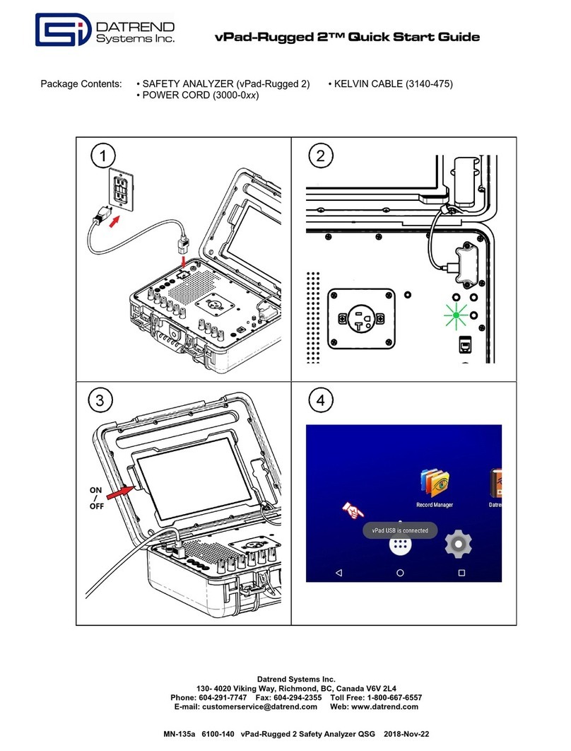
DATREND Systems vPad-Rugged 2 User manual
DATREND Systems
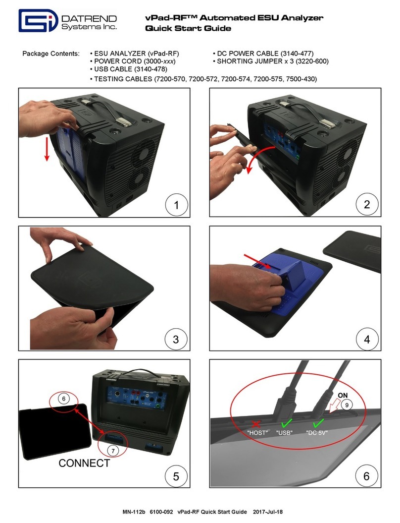
DATREND Systems vPad-RF User manual
DATREND Systems
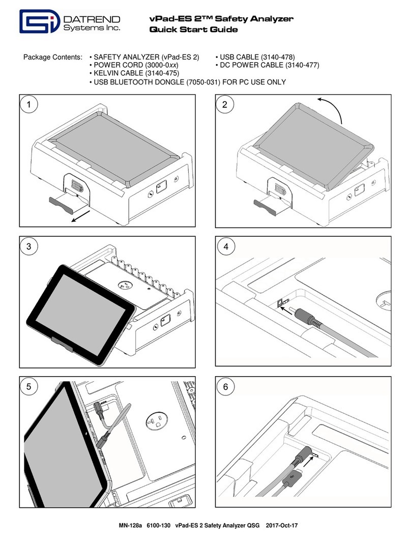
DATREND Systems vPad-ES 2 User manual
DATREND Systems
DATREND Systems vPad-IV User manual
DATREND Systems
DATREND Systems Vision Pad User manual
Popular Measuring Instrument manuals by other brands
Decagon Devices
Decagon Devices SC-1 quick start guide
DV Power
DV Power RMO100G manual
Digital Video Broadcasting
Digital Video Broadcasting PROMAX CABLE RANGER Quick reference guide

AquaMaster Tools
AquaMaster Tools Combo Pen P150 Pro user manual
Rohde & Schwarz
Rohde & Schwarz FSB operating manual

Steinberg Systems
Steinberg Systems SBS-RL-500R user manual


