DATREND Systems vPad-Mini User manual

Operating Manual
MN-125b
vPad -Mini™
vPad Safety Analyzer


vPad -Mini™
vPad Safety Analyzer
Operating Manual
© 2019 - 2020 Datrend Systems Inc.
Unit 130 - 4020 Viking Way
Richmond, BC • CANADA • V6V 2L4
Tel: 800.667.6557 (North America Only) or
604.291.7747 • Fax 604.294.2355
e-mail: [email protected]


To order this manual, use Part Number 6100-134
Revision
Revision History
Description Date
A Initial release 2019-Aug-22
BRevisions for Recording and
Automation 2020-Feb-13
Copyright
Datrend Systems Inc. (“DSI”) agrees to a limited copyright release that allows you to reproduce manuals and other
printed materials for use in service training programs and other technical publications. If you would like other
reproductions or distributions, submit a written request to Datrend Systems Inc.
Unpacking and Inspection
Follow standard receiving practices upon receipt of goods. Check the shipping carton for damage. If damage is
found, stop unpacking. Notify the freight carrier and ask for an agent to be present while the goods are unpacked.
There are no special unpacking instructions, but be careful not to damage the goods when unpacking. Inspect the
goods for physical damage such as bent or broken parts, dents, or scratches.
ClMM14
Our routine method of shipment is via common carrier. Upon delivery, if physical damage is found, retain all packing
materials in their original condition and contact the carrier immediately to file a claim. If the goods are delivered in
good physical condition but does not operate within specifications, or if there are any other problems not caused by
shipping damage, please contact your local sales representative or DSI immediately.
Standard Terms and Conditions
Refunds & Credits
Please note only serialized products (products labelled with a distinct serial number) and accessories are eligible for
partial refund and/or credit. Non-serialized parts and accessory items (cables, carrying cases, auxiliary modules,
etc.) are not eligible for return or refund. In order to receive a partial refund/credit, the product must not have been
damaged, and must be returned complete (meaning all manuals, cables, accessories, etc.) within 90 days of original
purchase and in “as new” and resalable condition. The Return Procedure must be followed.
Software which has been activated may not be returned for credit. Use it in Demo mode where possible to ensure
suitability for purpose.
Return Procedure
Every product returned for refund/credit must be accompanied by a Return Material Authorization (RMA) number,
obtained from Datrend Customer Service. All items being returned must be sent prepaid (freight, duty, brokerage,
and taxes ) to our factory location.
Restocking Charges
Product returned within 30 days of original purchase are subject to a minimum restocking fee of 15%. Product
returned in excess of 30 days after purchase, but prior to 90 days, are subject to a minimum restocking fee of 20%.
Additional charges for damage and/or missing parts and accessories will be applied to all returns. Product which is
not in “as new” and resalable condition, are not eligible for credit return and will be returned to the customer at their
expense.
Certification
This instrument was thoroughly tested and inspected and found to meet DSI’s specifications when it was shipped
from the factory.
Where applicable, calibration measurements are traceable to the National Research Council of Canada (NRC)
and/or the National Institute of Standards and Technology (NIST). Devices for which there are no NRC/NIST
calibration standards are measured against in-house performance standards using accepted test procedures.
Page i

Warranty
Warranty and Product Support
Software Applications (Apps) for use in conjunction with ES601 and vPad Safety Analyzers and other Datrend
Products are supplied subject to the Terms and Conditions agreed to by the act of Activating the App. In the event
no Activation is required, the Terms and Conditions published on the Datrend Systems Inc. (DSI) website shall
prevail. By using the App, you agree to these terms and Conditions. IN NO EVENT SHALL DATREND SYSTEMS
INC. BE LIABLE FOR CONSEQUENTIAL DAMAGES.
DSI DISCLAIMER ALL OTHER WARRANTIES, EXPRESSED OR IMPLIED, INCLUDING ANY WARRANTY OF
MERCHANTABILITY OR FITNESS FOR A PARTICULAR PURPOSE OR APPLICATION.
vPad™, vPad-XPORT™, vPad-ES™, vPad-353™, vPad-AS™, vPad-A3™,vPad-Record Manager™, vPad-RM™ ,
vPad-EQM™, vPad-Check™, vPad-Cal™, vPad-mT™, vPad-AIMS™, vPad-Medimizer™, vPad-TMA™,
vPad-Medusa™, vPad-RF™, Datrend Docs™, and CMX™ are trademarks of Datrend Systems Inc.
Android™ is trademark of Google Inc.
Page ii
vPad-Mini OPERATORS MANUAL
Table of Contents
TABLE OF CONTENTS ..............................................III
1OVERVIEW .................................................... 1
2MANUAL TESTING ............................................... 3
3RECORDING RESULTS ........................................... 17
4AUTOMATED TESTING ........................................... 23
5UPGRADES AND MAINTENANCE .................................... 45
Table of Contents #Page iii

vPad-Mini OPERATORS MANUAL
Table of Contents #Page iv

vPad-Mini OPERATORS MANUAL
1 Overview
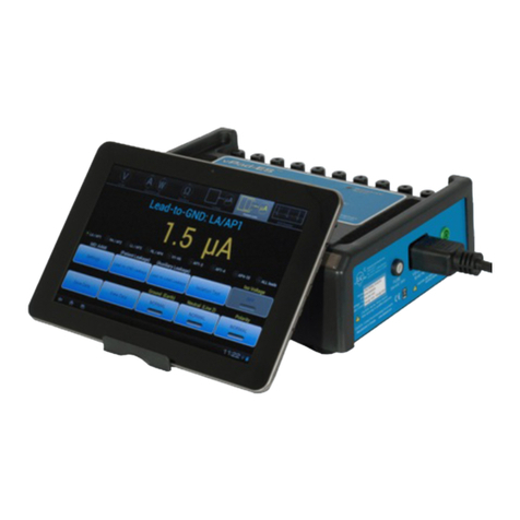
vPad-Mini™ is an electrical safety analyzer designed for manual safety testing in an environment with
limited need for Applied Parts testing. Options are available to: a) record measurements, create test records
and use Bluetooth communications to print or transfer the records; or. b) automate the safety test
according to the following standards: IEC62353, IEC61010, AU/NZ 3551 or NFPA99.
Overview/Chapter 1 #Page 1

vPad-Mini OPERATORS MANUAL
Overview/Chapter 1 #Page 2

vPad-Mini OPERATORS MANUAL
Figure 1
2 Manual Testing
2.1 General
The vPad-Mini app, in its most basic mode, is a manual electrical safety tester. Test results are only saved if
you manually record the measurement value. There is no evaluation of passing or failing against any limit
values you wish to impose. After applying power to the smart phone, the main menu of the application is
shown (Figure 1). Note that the main menu appearance will change as the recording and the automation
options are enabled: the number of buttons will change from 2 to 3 to 4 respectively.
The UI of the main menu includes image buttons which launch other activities of the app, including
measurement activities such as voltage , equipment current , ground resistance and leakage
, as well as application and device settings . Context-sensitive help is accessed on this and other
screens by a button.
Installation/Chapter 2 #Page 3

vPad-Mini OPERATORS MANUAL
Figure 2
If there is a problem during initialization of the hardware, an Alert Dialog is shown (Figure 2).
Fault messages which may be shown by the dialog are:
Error Message Shown if...
Analyzer electronics off-line !
Check AC supply input.
Attempt to connect with
analyzer via DACOM times out
Analyzer will not initialize !
Service is required.
No response to hardware
initialization command, or
No response to hardware idle
command
Unable to calibrate voltmeter !
Service is required.
No response to voltmeter
calibration command
Voltmeter offset is too high !
Service is required.
Response to command exceeds
maximum # of counts
The Close button dismisses the dialog and retries making a communication connection. If the hardware
fault cannot be corrected, operation loops indefinitely on the dialog until the phone is switched off.
Installation/Chapter 2 #Page 4

vPad-Mini OPERATORS MANUAL
Figure 3
2.2 Settings
The button on the main menu of the app launches a Settings Menu (Figure 3).
A spinner control sets the electrical safety standard (Figure 4). This setting affects the types of tests
provided by measurement activities of the app, as well as nomenclature which is displayed by those
activities.
Figure 4
Standards supported by vPad-Mini are AAMI-ES1, NFPA 99, IEC 60601, IEC 62353, IEC 61010, VDE751
and AU/NZ 3551. On first run of the app, the default standard will be AAMI-ES1. The selected standard
appears on most menus of the app, including the main menu where it is shown above the button.
Installation/Chapter 2 #Page 5

vPad-Mini OPERATORS MANUAL
Figure 5
Figure 6
A second spinner control sets the polarity switching delay (Figure 5). This setting applies to the leakage test
activity and determines the amount of time the test receptacle is maintained in the OFF state between
changes in polarity from normal to reverse or vice versa.
Available settings are 2, 4, 6 or 8 seconds. On first run of the app, the default setting is 2 seconds.
In Figure 3, there is a Main Menu AC Power setting. The user has the option of leaving the AC Power ON
(per Figure 3) whenever you go back to the Main Menu from a measurement that had the receptacle ON, or
having the AC Power turned OFF whenever you return to the Main Menu ( Always OFF).
The button displays the Android Settings of the phone (Figure 6). Except for language and perhaps
the sound volume, users will normally have no need to change the settings of the phone itself. However,
access to the Apps submenu of the Android Settings will be necessary if the vPad-Mini app needs to be
updated in the field with a new version, or you wish to use QuickSupport (from Teamviewer) for remote
support. The Android Settings menu will also enable the vPad-Mini phone to be paired with the customer's
phone or tablet over Bluetooth, which will be necessary if data recording, automation and reporting
capabilities are activated in the future.
Installation/Chapter 2 #Page 6

vPad-Mini OPERATORS MANUAL
Figure 7
The phone's BACK button is used to exit the Android Settings menu.
The button of Figure 3 saves changes, if any, to the safety standard, polarity delay and/or receptacle
status on returning to the Main Menu, and closes the Settings Menu.
2.3 Voltage
The button of the main menu launches a voltage measurement (Figure 7).
A numeric readout occupies the entire upper half of the screen. The measured value is updated
approximately once per second.
Image buttons occupying the bottom half of the screen enable the user to control the safety analyzer.
The button finishes the measurement and returns the UI to the main menu. The phone's BACK
button is disabled.
The button displays help information relevant to this menu.
Installation/Chapter 2 #Page 7

vPad-Mini OPERATORS MANUAL
Figure 8
The large central button selects the type of measurement to be performed.
2.3.1 The button displays a schematic image which represents the measurement being displayed
on the upper half of the screen.
2.3.2 Initially the button image is set to L1-L2 voltage.
2.3.3 When the central button is pressed, a pop-up pick list is then shown which allows the user to
change the type of measurement, Figure 8.
As shown in Figure 8, this list provides four measurements: L1-L2; L1-GND; L2-GND and
point-to-point voltage. The nomenclature of the pick list depends on the standard which has
been selected via the Settings Menu of Section 2 (AAMI and NFPA standards measure
"line" voltages; IEC standards measure "mains" voltages).
2.3.4 When an item on the pick list is chosen, the list is dismissed and the schematic on the central
button is updated to reflect the new test, and the selection label is copied to the text field
above the schematic.
The toggle button at bottom right controls the test receptacle.
The button icon includes a representation of a LED indicator, which appears bright green when the
receptacle is ON or grey when the receptacle is OFF.
Installation/Chapter 2 #Page 8

vPad-Mini OPERATORS MANUAL
Figure 9
2.4 Load Current Activity
The button on the main menu measures and displays load current. This measurement is somewhat
simpler than others on the app since it provides only one type of measurement.
A numeric readout occupies the entire upper half of the screen. The measurement value is updated
approximately once per second.
The button finishes the measurement and returns to the main menu. The phone's BACK button
is disabled.
The button displays help information relevant to this menu.
A schematic diagram is shown between and buttons which represents the test configuration. This
is an image only, not a button. A description of the test is placed in a text field above the schematic.
On entering the menu, the test receptacle is automatically switched ON if it is not already ON. Exiting this
activity with the button does not change the state of the test receptacle, so it will remain ON while
the main menu is being viewed.
Installation/Chapter 2 #Page 9

vPad-Mini OPERATORS MANUAL
Figure 10
2.5 Resistance
The button on the main menu starts a resistance measurement (Figure 10). The UI of this activity is
similar in design to the UI for the voltage measurement (see Section 3).
A numeric readout occupies the entire upper half of the screen. The measurement value is updated
approximately once per second.
All measurement results are obtained with a dedicated ohmmeter circuit which measures over a single range
up to ~2 ohms.
Image buttons occupying the bottom half of the screen enable the user to control the safety analyzer.
The button finishes the measurement and returns the UI to the main menu. The phone's BACK
button is disabled.
The button displays help information relevant to this menu..
The large central button selects the type of measurement to be performed.
2.5.1 The button displays a schematic image which represents the measurement being displayed
on the upper half of the screen.
2.5.2 On initial entry to the resistance measurement, the button image is set to power cord or
protective earth resistance. This means that, in addition to enabling the ohmmeter circuitry,
the test receptacle will be switched OFF if it is currently ON.
Installation/Chapter 2 #Page 10

vPad-Mini OPERATORS MANUAL
Figure 11
2.5.3 When the central button is pressed a pop-up pick list is then shown which allows the user to
change the type of measurement.
As shown in Figure 11, this activity provides two measurements: power cord or PE
resistance and point-to-point resistance. The nomenclature of the pick list depends on the
standard which has been selected via the Settings Menu described in Section 2.2 (AAMI and
NFPA standards measure "power cord" resistance; IEC standards measure "protective
earth" resistance).
2.5.4 When a item on the pick list is chosen, the list is dismissed and the schematic on the central
button is updated to reflect the new test, and the label for the selection is copied to the text
field above the schematic.
The toggle button at bottom right controls the test receptacle. Note that it will be OFF when
testing the power cord, and may be OFF or ON when testing point-to-point resistance.
The button icon includes a representation of a LED indicator, which appears bright green when the
receptacle is ON or grey when the receptacle is OFF.
Installation/Chapter 2 #Page 11

vPad-Mini OPERATORS MANUAL
Figure 12
2.6 Leakage Currents
The button on the main menu initiates leakage current measurements (Figure 12). The UI of this
activity is highly dependant on the setting of the standard, and in this way the leakage measurements differs
somewhat from other parameters.
A numeric readout occupies the upper right corner of the screen. The measurement value is updated
approximately once per second.
The metering circuitry provides two filter settings. The AAMI filter is selected when the standard is set to
AAMI only. For all other standards, the IEC filter is used.
When the standard is set to IEC61010 and the selected test is "Accessible Voltage", an alternative
measurement process is used which is analogous to the point-to-point measurement of the voltage activity.
Image buttons on the bottom half of the screen enable the user to control the leakage test.
On initial entry to leakage current testing the button icons default to show normal polarity and (depending
on the standard) normal neutral and ground.
The button displays help information relevant to this menu.
The "ground button" controls the ground or earth connection at the test receptacle.
Installation/Chapter 2 #Page 12
Table of contents
Other DATREND Systems Measuring Instrument manuals

DATREND Systems
DATREND Systems Vision Pad User manual

DATREND Systems
DATREND Systems vPad-IV User manual

DATREND Systems
DATREND Systems vPad-ES 2 User manual

DATREND Systems
DATREND Systems vPad-RF User manual

DATREND Systems
DATREND Systems vPad-Rugged 2 User manual

DATREND Systems
DATREND Systems vPad-XSC User manual
Popular Measuring Instrument manuals by other brands

Heise
Heise CC Installation and maintenance manual

SPI
SPI 94200 Operation installation and maintenance

Anaheim Scientific
Anaheim Scientific P773 user manual

Tintometer
Tintometer Lovibond MD100 instruction manual

Fluke Calibration
Fluke Calibration KIT-EMM300 instructions

LLG
LLG pH meter 7 instruction manual