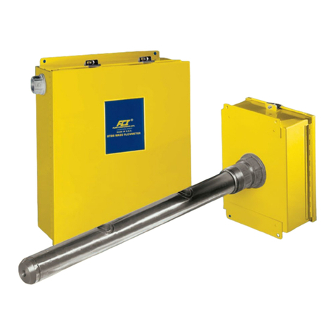
FCI FLT93B Instruction manual

FLT®93 Series FlexSwitch™
Flow, Level, Temperature Switch / Monitor
Models: FLT93B, FLT93C, FLT93F,
FLT93L, FLT93S
Installation, Operation
& Maintenance Manual
Installation, Betrieb und Wartungshandbuch
Manual de Instalación, Operación y Mantenimiento
安装、操作和维护手册
Fluid Components International LLC (FCI). All rights reserved.
Doc. No. 06EN003401

FLT®Series FlexSwitchTM
Fluid Components International LLC
Notice of Proprietary Rights
This document contains confidential technical data, including trade secrets and proprietary information which is the property of Fluid
Components International LLC (FCI). Disclosure of this data to you is expressly conditioned upon your assent that its use is limited to use with-
in your company only (and does not include manufacture or processing uses). Any other use is strictly prohibited without the prior written consent of FCI.
© Copyright 2018 by Fluid Components International LLC. All rights reserved.
Manufactured in accordance with one or more of the following patents: 5,600,528; 6,340,243. FCI is a registered trademark of Fluid Components International LLC. Information subject to change without notice.

FLT®Series FlexSwitchTM 06EN003401 Rev. C
Fluid Components International LLC iii
Table of Contents
1 GENERAL.....................................................................................................................................................................................................1
Description........................................................................................................................................................................................................................1
Theory of Operation..........................................................................................................................................................................................................1
Sensing Element...............................................................................................................................................................................................................1
Control Circuit...................................................................................................................................................................................................................1
Technical Specifications ...................................................................................................................................................................................................2
2 INSTALLATION...........................................................................................................................................................................................5
Receiving/Inspection........................................................................................................................................................................................................5
Packing/Shipping/Returns................................................................................................................................................................................................5
Factory Calibration Note...................................................................................................................................................................................................5
Pre-Installation Procedure................................................................................................................................................................................................5
Use Standard ESD Precautions.....................................................................................................................................................................................5
Prepare or Verify Sensing Element Location.................................................................................................................................................................5
Verify Dimensions .........................................................................................................................................................................................................5
Verify Sensing Element Flow Direction and Placement Orientation (Flow Application) ..............................................................................................5
Verify Sensing Element Flow Direction and Placement Orientation (Level Application) .............................................................................................5
Install the Sensing Element..............................................................................................................................................................................................6
Male NPT Mounting......................................................................................................................................................................................................6
Flange Mounting ...........................................................................................................................................................................................................6
Packing Gland Assembly...............................................................................................................................................................................................7
In-line NPT Assembly (FLT93L) ......................................................................................................................................................................................7
Sanitary Assembly (FLT93C) ..........................................................................................................................................................................................8
Install and Wire the Enclosure(s) .....................................................................................................................................................................................8
Disconnect Device.........................................................................................................................................................................................................8
Minimum Wire Size.......................................................................................................................................................................................................8
Enclosures Covers .........................................................................................................................................................................................................8
Cable and Conduit Entry Devices..................................................................................................................................................................................9
Enclosure Grounding .....................................................................................................................................................................................................9
Wiring the Local Enclosure Configuration ..................................................................................................................................................................11
Wiring The Remote Enclosure Configuration..............................................................................................................................................................12
Locate the Remote Hardware Location.......................................................................................................................................................................12
Wiring Output Signal Terminals .....................................................................................................................................................................................13
Wiring Input Power.........................................................................................................................................................................................................13
3 OPERATION ..............................................................................................................................................................................................17
Factory Default Jumper Configuration ...........................................................................................................................................................................17
Configuration Jumpers ...................................................................................................................................................................................................17
Heater Cut-Off ................................................................................................................................................................................................................17
Alarm Setpoint Adjustments..........................................................................................................................................................................................18
Numerical Adjustment Versus Adjustment by Observation .......................................................................................................................................18
Numerical Alarm Setpoint Adjustment..........................................................................................................................................................................19
Air/Gas Flow Applications ..........................................................................................................................................................................................19
Wet/Dry Liquid Level Applications .............................................................................................................................................................................22

06EN003401 Rev. C FLT®Series FlexSwitchTM
iv Fluid Components International LLC
Liquid Flow Applications.............................................................................................................................................................................................23
Adjustment by Observation............................................................................................................................................................................................25
Flow Applications........................................................................................................................................................................................................25
Level Applications.......................................................................................................................................................................................................26
Temperature Applications ..............................................................................................................................................................................................26
Converting Temp Out Voltage to Temp in Degrees F or Degrees C ............................................................................................................................28
Fail-Safe Alarm Setting.................................................................................................................................................................................................34
Low Flow Alarm Settings............................................................................................................................................................................................34
High Flow Alarm Settings ...........................................................................................................................................................................................34
Low Level Alarm Settings (Sensing Element Normally Wet) ....................................................................................................................................35
High Level Alarm Settings (Sensing Element Normally Dry).....................................................................................................................................35
4 MAINTENANCE .......................................................................................................................................................................................37
Maintenance...................................................................................................................................................................................................................37
Calibration...................................................................................................................................................................................................................37
Cleaning.......................................................................................................................................................................................................................37
Electrical Connections.................................................................................................................................................................................................37
Remote Enclosure........................................................................................................................................................................................................37
Electrical Wiring..........................................................................................................................................................................................................37
Sensing Element Connections.....................................................................................................................................................................................37
Sensing Element Assembly.........................................................................................................................................................................................37
5 TROUBLESHOOTING...............................................................................................................................................................................39
Tools Needed...............................................................................................................................................................................................................39
Quick Check.................................................................................................................................................................................................................39
Non-maintenance Observations..................................................................................................................................................................................39
Check Serial Numbers.................................................................................................................................................................................................39
Check Input Power.......................................................................................................................................................................................................39
Check the Instrument Installation...............................................................................................................................................................................39
Check for Moisture......................................................................................................................................................................................................39
Check Application Design Requirements....................................................................................................................................................................39
Troubleshooting the Flow Element.................................................................................................................................................................................40
Troubleshooting the Control Circuit................................................................................................................................................................................42
Enclosures ...................................................................................................................................................................................................................43
Spares..........................................................................................................................................................................................................................43
Defective Parts............................................................................................................................................................................................................43
Customer Service ........................................................................................................................................................................................................43

FLT®Series FlexSwitchTM 06EN003401 Rev. C
Fluid Components International LLC v
APPENDIX A DRAWINGS .........................................................................................................................................................................45
APPENDIX B GLOSSARY...........................................................................................................................................................................75
APPENDIX C APPROVAL INFORMATION...............................................................................................................................................77
EC Information.............................................................................................................................................................................................................77
Safety Instructions for the Use of the FLT93 Flowswitch in Hazardous Areas...........................................................................................................79
Annex 1........................................................................................................................................................................................................................83
SIL Information............................................................................................................................................................................................................89
APPENDIX D TEMPERATURE COMPENSATION ...................................................................................................................................91
Introduction.....................................................................................................................................................................................................................91
Factory Temperature Compensation Settings................................................................................................................................................................91
Balance Procedure..........................................................................................................................................................................................................92
Field Temp Comp Calibration..........................................................................................................................................................................................92
APPENDIX E CUSTOMER SERVICE.........................................................................................................................................................95
Customer Service/Technical Support..........................................................................................................................................................................95
Warranty Repairs or Returns.......................................................................................................................................................................................95
Non-Warranty Repairs or Returns...............................................................................................................................................................................96
Extended Warranty......................................................................................................................................................................................................96
Return to Stock Equipment..........................................................................................................................................................................................96
Field Service Procedures.............................................................................................................................................................................................96
Field Service Rates......................................................................................................................................................................................................96

06EN003401 Rev. C FLT®Series FlexSwitchTM
vi Fluid Components International LLC
INTENTIONALLY LEFT BLANK

FLT®Series FlexSwitchTM GENERAL
Fluid Components International LLC 1
1 GENERAL
Description
The FLT Series models are multipurpose measurement instruments. The models included in this manual are FLT93B (Basic), FLT93C (Sanitary), FLT93F
(Fast Response), FLT93L (In-Line) and FLT93S (Heavy Duty). Each model is a single instrument that is capable of detecting fluid flow and temperature.
It is also able to detect liquid level or fluid media interfaces. The instrument has two field adjustable alarm setpoints, two buffered voltage outputs,
as well as a built-in calibration circuit. The output of the alarm setpoints are relay contacts that can be used to control customer process applications.
One buffered voltage output is available for flow or level monitoring and the second buffered voltage output is available for temperature monitoring.
Theory of Operation
The flow switch is a fixed position, single-point flow, level, interface and temperature switch. The operation of the sensing element is based upon the
thermal dispersion principle: A low-powered heater is used to produce a temperature differential between two Resistance Temperature Detectors
(RTDs). The RTD temperature differential varies as a function of forced convection for flow measurement and as a function of fluid thermal conductiv-
ity for level and interface measurement. The measurement of the fluid’s temperature is obtained from the non-heated RTD.
Sensing Element
The sensing element consists of two thermowells (hollow tubes) that when inserted into the flow process allows an unimpeded flow inside the process
line. The top thermowell has a heated RTD inserted into it. The bottom thermowell has a reference RTD inserted into it. In order to correctly orient the
sensing element a flow arrow has been etched onto the threaded portion of the sensing element. See Figure 1-1 for a view of the sensing element.
Control Circuit
The control circuit converts the sensing element’s RTD temperature differential into an analog DC voltage signal. Dual comparators monitor the sens-
ing element signal and activates the relay alarm circuits if the signal exceeds an adjustable setpoint.
The control circuit contains field selectable jumpers that are used to configure the instrument for the application.
Figure 1-1 View of the Sensing Element

GENERAL FLT®Series FlexSwitchTM
2 Fluid Components International LLC
Application
Flow rate and/or level/interface and temperature sensing in liquid,
gas and slurry applications.
Sensing Element
Process Connection
Model B
Standard: 3/4” male NPT.
Models S and F
Standard: 3/4” male NPT.
Optional: 1” BSP, 1” or 1 1/4” male NPT; flanges, spool pieces,
sanitary fittings or retractable sensing element.
Model L
Standard: 1” male NPT or 3/4” female NPT.
Optional: Flange and low-flow orifice.
Model C
Standard: Sanitary flange
Insertion Length
Model B
Standard: 1.2” [30 mm], 2” [51 mm], 4” [102 mm].
Models S and F
Standard: 1.2” [30 mm], 2” [51 mm], 4” [102 mm], 6” [152 mm], 9”
[229 mm], 12” [305 mm],18” [457 mm].
Optional: Custom-specified lengths.
Model L
Threaded connections: 3.375” [86 mm] in-line body length.
Flanged connections: 12” [305 mm] in-line body length.
Model C
See chart on outline dimensional, Appendix A.
Sensor Wetted Materials
Model B
Standard: 316L stainless steel with all-welded construction.
Models S and F
Standard: 316L stainless steel with all-welded construction.
Optional: Hastelloy C, Monel 400, electro-polished stainless steel
and titanium (FLT93S only). Other spray coatings are available on
special request (i.e., tantalum, chromium carbide, Kynar).
Model L
Standard: 316L stainless steel with all-welded construction.
Optional: Hastelloy C, Monel 400 and titanium.
Model C
Standard: 316L stainless steel with all-welded construction
electro-polished to 20 Ra.
Operating Temperature
All Models
Standard temperature configuration:
-40 °F to +350 °F [-40 °C to +177 °C]
Medium temperature configuration:
-100 °F to +500 °F [-73 °C to +260 °C]
Model S Only
High temperature configuration:
-100 °F to +850 °F [-73 °C to +454 °C]
Operating Pressure (w/NPT Process Connection)
Models S, B, F and L
2350 psig [162 bar(g)] -100 °F to 500 °F [-73 °C to 260 °C]
Models S, B
1450 psig [100 bar(g)] 501 °F to 850 °F [261 °C to 454 °C]
Model C
1500 psig [103 bar(g)] -100 °F to 500 °F [-73 °C to 260 °C]
Higher ratings available with special construction and test certification.
Environmental Conditioning
Indoor or outdoor use.
Maximum Relative Humidity: 100%
Maximum Altitude: 12,000 ft.
Control Circuit (5208)
Configuration
Standard: Plug-in, socket mounted with dual alarm/trip epoxy sealed relays.
Optional: Rack-mount configuration (card cage or enclosure not
included).
Output Signals
Standard: Analog DC voltage related to flow or level/interface signal
and analog DC voltage proportional to temperature.
Input Power
Standard: Field selectable for 120 VAC (108-132 VAC), 13 W 100 mA
maximum; 230 VAC (207-253 VAC), 14 W 50 mA maximum;
24 VDC (21-30 VDC), 7 W, 230 mA maximum or 24 VAC (18-28 VAC),
7 W, 230 mA maximum.
Optional: Low supply voltage operation for applications with line
voltage supplies lower than 108 VAC. Field selectable for 100 VAC
(90-110 VAC), 13 W, 100 mA maximum; 200 VAC (180-220 VAC)
14 W, 50 mA maximum.
All AC power rated at 50-60 Hz.
Power “ON” amber LED provided.
Serviceable Fuse Rating
For the 120/230 VAC input power configuration, there are two
serviceable fuses located on the top side of the control circuit. These
are labeled F1 and F2.
Fuse Specifications
Power: 1.6 amps, 250 VAC, Slo-Blo®(time delay)
Package size: TRS (8.5 x 8 mm) radial lead plug-in type
FCI part number: 019933-01
Tyco part number: 37411600410
For the 24 VDC/VAC input power configuration, there is a fuse
located on the bottom side of the control circuit. The replacement of
this fuse requires a qualified technician knowledgeable in SMD, and
RoHS soldering practices.
Fuse Specifications
Power: 1.5 amps, 125 VDC, SLO-BLO®(time delay)
Package size: 6.1 x 2.69 mm SMD
FCI part number: 020399-02
Littelfuse part number: 045201.5
Heater Power
Field or factory selected to optimize switching performance and
rangeability and selectable for specific fluid service requirements.
Typical Service Sensing Element Power (W)
Gas or Air S/B-Style 0.75
F-Style 0.25
Liquids S/B-Style 3.0
Technical Specications

FLT®Series FlexSwitchTM GENERAL
Fluid Components International LLC 3
The above typical service power selections are for reference only. De-
pending on application requirements, surface temperature rating require-
ments, and rangeability expectations, alternate power selections may be
recommended. Other intermediate power selections can be made.
Relay Rating
Standard: Dual alarm, SPDT or single alarm DPDT field
configurable, 6 amps resistive load at 240 VAC, 120 VAC, 24 VDC.
Optional: Dual alarm SPDT or single alarm DPDT field configurable
hermetically sealed relay, 0.5 amps at 115 VAC/2 amps at 28 VDC.
Electrical Enclosure
Aluminum (epoxy coated) or optional stainless steel. Enclosures are
rated for hazardous location use (Class I and II, Division 1 and 2,
Group B, C, D, E, F and G; and EEx d IIC) and weather and corrosion
resistant (NEMA and CSA Type 4X and equivalent to IP66).
Operating Temperature
Ambient -40 °F to +140 °F [-40 °C to + 60 °C]
For Flow Service
Setpoint Range
Models S, B
Water-based Liquids:
0.01 FPS to 0.5 FPS [0.003 MPS to 1.52 MPS] with 0.75 watt heater;
0.01 FPS to 3.0 FPS [0.003 MPS to 0.9 MPS] with 3.0 watt heater.
Hydrocarbon-based Liquids:
0.01 FPS to 1.0 FPS [0.003 MPS to 0.3 MPS] with 0.75 watt heater;
0.01 FPS to 5.0 FPS with [0.003 MPS to 1.5 MPS] with 3.0 watt heater.
Air/Gas:
0.25 SFPS to 120 SFPS [0.08 NMPS to 37 NMPS] with 0.75 watt heater
at standard conditions; 70 °F [21.1 °C], 14.7 psia [1.013 bar(g)].
Other Fluids: Contact the factory for approximate rangeability.
Model F
Air/Gas:
0.25 SFPS to 120 SFPS [0.08 NMPS to 37 NMPS] 0.25 watt heater
at standard conditions; 70 °F [21.1 °C], 14.7 psig [1.013 bar(g)].
Model L
Water-based Liquids: 0.015 cc/sec to 50 cc/sec
Hydrocarbon-based Liquids: 0.033 cc/sec to 110 cc/sec
Air/Gas: 0.6 cc/sec to 20,000 cc/sec
Model C
Water-based Liquids: 0.01 FPS to 3.0 FPS [0.003 MPS to 0.9 MPS]
Syrup: to 5.0 FPS [0.0003 MPS to 1.5 MPS]
Air/Gas: 0.25 SFPS to 120 SFPS [0.08 NMPS to 36.6 NMPS]
Factory Calibrated Switch Point Accuracy
Any flow rate within the instrument flow range may be selected as a
setpoint alarm. A factory-calibrated setpoint adjustment may be
optimally preset with accuracy of ±2% of setpoint velocity over an
operating temperature range of ±50 °F [±28 °C].
Monitoring Accuracy
Based on the non-linear output voltage (P1, pins 1 & 2) over the en-
tire flow range, a 100 °F (56 °C) max. temperature span, and a max.
operating pressure range of ±100 psig [±7 bar(g)]:
Liquids: ±5% reading or ±0.04 SFPS [±0.012 NMPS], whichever is larger.
Gases: ±5% reading or ±2 SFPS [±0.61 NMPS], whichever is larger.
Repeatability
±0.5% reading
For Level/Interface Service
Accuracy
Models S, B
±0.25” [±6.4 mm]
Model F
±0.1” [±2.5 mm]
Repeatability
Models S, B
±0.125” [±3.2 mm]
Model F
±0.05” [±1.3 mm]
For Temperature Service
Accuracy
±2.0 °F [±1 °C] with field setpoint adjustment. Monitoring accuracy
±3.5 °F [±2 °C] with standard curve fit output voltage operation
across the selected instrument temperature range. Higher accuracy
available with factory calibrations.
Repeatability
±1.0 °F [±0.6 °C]
The above accuracy is based on liquid or slurry service and in gas service
with a minimum 1 SFPS [0.3 NMPS] velocity past the sensing element or
with the heater deactivated for temperature sensing service only.
SIL: SIL-2 compliant, safe failure fraction (SFF) 82% to 84%
Factory Application-Specic Setup and Setpoint Calibration
Standard instrument factory default settings (unless otherwise
selected at order entry):
• 120 VAC input power for all domestic units.
• 230 VAC for all other agency approval units. Field selectable.
• Dual SPDT alarms set for:
Alarm No. 1: Preset for flow or level and to de-energize with
decreasing conditions.
Alarm No. 2: Preset to de-energize for increasing temperature at
10 °F [5 °C] below the maximum instrument process temperature.
• Heater power at 0.25 watt on Model F or 0.75 watt on Model S/B.
• Mode switch set to “operate”.
Factory calibration including set up for specific service, process fluid
and alarm conditions optionally available. Contact factory for fluid
handling capabilities.
Agency Approvals
FM, FMc XP, Class I, Division 1, Groups B, C, D
DIP, Class II/III, Division 1, Groups E, F, G
T4, Ta = 60 °C; T3A, Ta = 60 °C
ATEX II 2 G Ex d IIC T6...T2 -40 °C to 60 °C Gb
IECEx Ex d IIC T6 or T5
Tamb (Housing) = -40 °C to 40 °C, T6
Tamb (Housing) = -40 °C to 60 °C, T5
Tp (Sensing Element) = -40 °C to 77 °C, T4
Tp (Sensing Element) = -40 °C to 177 °C, T2
Other Certifications: SIL-2 rated, CRN, probe complies with Cana-
dian Electrical Code requirements of ANSI/ISA 12.27.01-2011 as a
single seal device, CE marking, RoHS2 compliant
Shipping Weight (approximate)
Integral: 8 lb [3.6 kg]
Remote: 13 lb [5.9 kg]

GENERAL FLT®Series FlexSwitchTM
4 Fluid Components International LLC
INTENTIONALLY LEFT BLANK

FLT®Series FlexSwitchTM INSTALLATION
Fluid Components International LLC 5
2 INSTALLATION
Receiving/Inspection
• Unpack carefully.
• Verify that all items in the packing list are received and are correct.
• Inspect all instruments for damage or contaminants prior to installation.
If the above three items are satisfactory, proceed with the installation. If not, then stop and contact a customer service representative.
Packing/Shipping/Returns
These issues are addressed in Appendix E - Customer Service.
Factory Calibration Note
The instrument is factory calibrated to the applications as specified at the time of order. There is no need to perform any verification or cali-
bration steps prior to installing and placing the instrument in service unless the application has changed.
Pre-Installation Procedure
Warning:
This instrument must be installed by qualified personnel only. Install and follow safety procedures in accordance with local
and national electrical codes and regulations. Ensure that power is OFF during installation. Any instances where power is ap-
plied to the instrument will be noted in this manual. Where the instructions call for the use of electrical current, the operator
assumes all responsibility for conformance to safety standards and practices.
Caution:
The instrument contains electrostatic discharge (ESD) sensitive devices. Use standard ESD precautions when handling the
control circuit. See below, for ESD details.
The instrument is not designed for weld-in-place applications. Never weld to a process connection or a structural support.
Damage resulting from moisture penetration of the control circuit or flow element enclosure is not covered by product warranty.
Use Standard ESD Precautions
Use standard ESD precautions when opening an instrument enclosure or handling the control circuit. FCI recommends the use of the fol-
lowing precautions: Use a wrist band or heel strap with a 1 megohm resistor connected to ground. If the instrument is in a shop setting use
workstations with static conductive mats on the work table and floor with a 1 megohm resistor connected to ground. Connect the instrument
to ground. Apply antistatic agents to hand tools to be used on the instrument. Keep high static producing items away from the instrument
such as non-ESD approved plastic, tape and packing foam.
For sensors and flanges containing titanium, ignition hazards due to impact or friction must be avoided according to EN/IEC 60079-0, clause 8.3.
The above precautions are minimum requirements to be used. The complete use of ESD precautions can be found in the U.S. Department Of
Defense Handbook 263.
Prepare or Verify Sensing Element Location
Prepare the process pipe for installation, or inspect the already prepared location to ensure that the instrument will fit into the system.
Review the requirement for the supply power and alarm circuit connections.
Verify Dimensions
Verify the instrument’s dimensions versus the process location to be sure of a correct fit. Also see Appendix A for dimensions.
Verify Sensing Element Flow Direction and Placement Orientation (Flow Application)
For flow detection, the sensing element surface marked with direction arrows should be oriented parallel to the process flow. The flow can be from either direction.
Mount the sensing element at least 20 diameters downstream and 10 diameters upstream from any bends or interference in the process pipe
or duct to achieve the greatest accuracy.
For liquid flow service, locate the sensing element in the process pipe so that the thermowells are always completely wet.
When mounted in a tee or section of pipe larger than the normal process pipe, position in a vertical run of pipe with flow upward. This will
prevent air or gas bubbles from becoming trapped at the sensor assembly.
Vertical positioning with flow downward is only recommended for higher flow rate applications (consult FCI).
Verify Sensing Element Flow Direction and Placement Orientation (Level Application)
If the sensing element is side-mounted on the process vessel, then the surface marked with direction arrows should be vertically oriented.
If the sensing element is top- or bottom-mounted on the process vessel, the orientation of the surface marked with direction arrows does not matter.

INSTALLATION FLT®Series FlexSwitchTM
6 Fluid Components International LLC
Figure 2-1 NPT Pipe Thread Mount
Figure 2-2 Flange Mount
Install the Sensing Element
Male NPT Mounting
When mounting the sensing element to the process pipe, it is important that a lubricant/sealant be applied to the male threads of all connec-
tions. Be sure to use a lubricant/sealant compatible with the process environment. All connections should be tightened firmly. To avoid leaks,
do not overtighten or cross-thread connections. See Figure 2-1 and the appropriate drawings in Appendix A for proper mounting.
Flange Mounting
For flange mounted sensing elements, attach the process mating flange with care. The correct orientation of the sensing element must be
maintained to ensure optimum performance or calibration. See Figure 2-2 and the appropriate drawings in Appendix A.

FLT®Series FlexSwitchTM INSTALLATION
Fluid Components International LLC 7
Packing Gland Assembly
For applications involving the use of a packing gland (low or medium pressure) refer to the drawings in Appendix A for additional detail.
1. Threaded or flanged packing gland mounts are available. The valve assembly with appropriate connections are customer supplied. Follow
the male NPT mounting procedure above to attach the pipe thread portion or flange mounting portion as applicable.
2. Tighten the packing nut until the internal packing is tight enough so that the friction fit on the shaft is adequate to prevent leakage but
not prevent the shaft from sliding. Position the etched flow arrow parallel with the flow (±1° of level) and position the flow arrow so it is
pointing in the direction of the flow.
3. Proceed to insert the probe into the process media line.
4. For medium pressure packing gland only (PGM): Use the adjusting nuts on the all-thread to pull the sensing element into proper predeter-
mined depth position.
5. For medium pressure packing gland only (PGM): Tighten the opposing lock nuts on the all-threads.
6. Tighten the packing nut another half to full turn until tight (approximately 65 to 85 ft-lbs [88 to 115 N-m] torque).
7. Rotate the split ring locking collar to line up with the connecting strap welded to the packing nut. Tighten the two 1/4-28 hex socket cap
screws on the split ring locking collar.
Reverse these steps for removal.
In-line NPT Assembly (FLT93L)
Check the body length of the in-line assembly to make sure the assembly will fit into the process line. See the appropriate drawing in Appen-
dix A to determine the assembly length. The direction of flow is important for proper operation. There is a flow direction arrow on the in-line
pipe that is to point in the direction of flow. See Figure 2-3 for the correct orientation.
If the instrument is a butt weld assembly, be sure to do the following: Remove the circuit board, properly ground the flow element before welding.
Figure 2-3 FLT93L In-Line Flow Element (Shown with 1-Inch MNPT Ports)

INSTALLATION FLT®Series FlexSwitchTM
8 Fluid Components International LLC
Sanitary Assembly (FLT93C)
The instrument is inserted into the process connection with removable clamp fittings. The Removable Clamp (RC) sanitary assembly contains
a removable clamp connection to the flow element. The Clean-In-Place (CIP) sanitary assembly has the flow element directly welded into the
process stand pipe. Otherwise these instruments function exactly the same as an FLT93F or FLT93S. See Appendix A for outline dimensions of
the instruments. Figure 2-4 also shows the sanitary assemblies.
Install and Wire the Enclosure(s)
Warning:
In applications where the sensing element is located in an explosive environment, isolate the conduit before it leaves the
environment. A silicone encapsulant/potting compound can be used to provide the isolation.
Install an input power disconnect switch and fuse near the instrument to interrupt power during installation and
maintenance.
Always disconnect/shut-off power before wiring
.
Caution:
Pulling wires can cause damage to the control circuit. Therefore, remove the control circuit from the enclosure and use
extreme care when pulling wires into the enclosure.
Mount and wire the control circuit either locally or remotely (option) by following the local or remote enclosure procedure below.
Disconnect Device
IEC 61010-1 requires the installation of an external switch or circuit breaker on the 120/220 VAC power source. It is recommended that the
switch or the circuit breaker be in close proximity to the flow switch and within easy reach of the operator. The recommended breaker trip
value for 120/220 VAC is 3 amps. If 24 VDC/VAC input power is being used a disconnect switch or breaker is also recommended. Recom-
mended breaker value is 3 amps. All disconnect devices shall be clearly marked for the flow switch.
Minimum Wire Size
Table 2-1 shows the smallest (maximum AWG number) copper wire that is used in the electrical cables. Use a lower gauge of wire for less
of a voltage drop. Contact FCI concerning greater distances than those listed in the table. The sensing element cable must be shielded. If the
cable is spliced the shield wire must be continued through the splice. If a terminal block is used, the shield must have its own terminal.
Enclosures Covers
All enclosure covers must be in place and securely closed to achieve environmental and safety classifications.
Tighten all circular thread-on covers about 1 full turn past hand tight.
Cover locks must be in place and secure if required by a particular approval.
Note:
Nitrile (buna-N) O-rings are standard on the circular thread covers. These O-rings have a 250 °F (121 °C) maximum usage
temperature.
A Viton O-ring [400 °F (204 °C) max. temp.] is available for the thread-on covers.
To receive a Viton O-ring, provide FCI with the following information:
• Shipping address
• Quantity required
• Desired P/N:
Use P/N 000391-01 for the single conduit port enclosure (Local)
Use P/N 000391-07 for the dual conduit port enclosure (Remote)
Figure 2-4 FLT93C Sanitary Flow Elements (RC and CIP)

FLT®Series FlexSwitchTM INSTALLATION
Fluid Components International LLC 9
Figure 2-5 Removing Ground Wire Securing Hardware from Enclosure
Cable and Conduit Entry Devices
The cable and conduit entry devices and blanking elements shall be of a certified flameproof type Ex db and Ex tb suitable for T ratings up to
106 °C, suitable for the conditions of use and correctly installed. With the use of conduit entries a sealing device shall be provided immedi-
ately on the entrance of the device.
All cable glands and conduit fittings, including conduit plugs, must meet or exceed the area approval where the unit is being installed.
Enclosure Grounding
To ensure an Ex-compliant installation, follow the below steps to ground the enclosure.
Warning:
Ensure that all power is OFF before wiring any circuit.
Tools required:
• Wire Stripper for 10-12 AWG (3.3-5.3 mm2)
• Crimping Tool for 10-12 AWG (3.3-5.3 mm2), TE Connectivity CERTI-CRIMP Direct Action Hand Tool 49935 (or equivalent)
• M4 hex key/Allen wrench
1. Strip .250”-.281” [6.35-7.14 mm] insulation from ground wire, stranded or solid (12-10 AWG).
Note: Avoid nicking or cutting wire strands when stripping the wire insulation.
2. Remove M4 socket cap screw, M4 split washer and ring lug from enclosure using M4 hex key (Allen wrench). The enclosure’s ground
wire hardware is installed at the factory. See Figure 2-5 below.
Connection
Maximum Distance for AWG
10 ft.
(3m)
50 ft
(15m)
100 ft.
(31m)
250 ft.
(76m)
500 ft.
(152m)
1000 ft.
(305m)
AC/DC Power 22 22 22 20 18 16
Relay (6A) 28 22 20 16 12 10
Flow Element Wires* 22 20 20 18 18 18
* Requires a shielded cable with the shield wire connected to the terminal board only.
Table 2-1 Maximum AWG Number
M4 HEX KEY RING LUG,
10-12 AWG
M4 SPLIT
LOCK WASHER
ENCLOSURE
M4 SOCKET
CAP SCREW C01332-1-1

INSTALLATION FLT®Series FlexSwitchTM
10 Fluid Components International LLC
3. Place center of ring lug barrel in appropriate crimping tool chamber. Squeeze tool handles together with just enough force to hold barrel
in place (do not deform barrel).
4. Insert stripped end of ground wire into barrel. Place the wire such that the insulation does not enter barrel and that the stripped wire end
does not extend beyond barrel.
5. While holding the wire in place, squeeze the tool handles together until the ratchet releases, then allow the tool handle to open fully.
See Figure 2-6.
Caution:
The crimping jaws bottom before ratchet releases. This feature ensures maximum electrical tensile performance of the crimp.
Do NOT re-adjust the ratchet.
Figure 2-6 Crimping Ground Wire Ring Lug
Figure 2-7 Installing Ring Lug Terminated Ground Wire
6. Install ground wire ring lug with end of lug barrel touching the side of the enclosure’s mounting boss as shown in Figure 2-7. Place the
ring lug on either side of the mounting boss as needed for the installation. Install with the hardware in this order: socket cap screw, split
lock washer, ring lug. Torque cap screw to 23 in-lb (2.6 N-m).
CRIMPING TOOL
RING LUG
RING LUG WITH
CRIMPED GROUND WIRE
C01333-1-1
(a) Enclosure Top View (b) Detail View
Position ring lug barrel
on either side of
enclosure’s
mounting boss.
ENCLOSURE
GROUND SCREW
MOUNTING BOSS
M4 SOCKET
CAP SCREW
SPLIT
LOCK WASHER
RING LUG
TERMINATED
GROUND WIRE
M4 HEX KEY
C01334-1-1

FLT®Series FlexSwitchTM INSTALLATION
Fluid Components International LLC 11
Figure 2-8 Local Wiring Diagram
Wiring the Local Enclosure Configuration
Warning:
Ensure that all power is OFF before wiring any circuit.
This procedure is for instruments with the control circuit located in the sensing element enclosure.
1. Remove the control circuit from the terminal board socket by loosening the two thumbscrews on top of the transformer bracket. Note: the
screws are captive. Note the orientation of the control circuit. Grab hold of the transformer bracket where the screws are and unplug the
control circuit from the terminal board by pulling on the transformer bracket.
2. Install conduit between the local enclosure, disconnect device and the power source and monitoring circuit. Provide watertight hardware
and apply thread sealant to all connections to prevent water damage.
3. Refer to the Wiring Input Power section at the end of this section for the available input power configurations. Input power wiring
configurations are the same for local and remote enclosure options and also any output relay configuration. Wire in accordance with the
system requirements.
4. When connecting the relay wiring, do so with complete understanding of what the process requires of the instrument. The instrument
has dual SPDT or single DPDT relay output contacts dependent on the jumper configuration for each alarm switch point. For the relay
terminals and logic, refer to Figure 2-8. Also refer to Table 3-5 and Table 3-6 in Section 3 - Operation. Relay contacts are shown with the
relays de-energized.

INSTALLATION FLT®Series FlexSwitchTM
12 Fluid Components International LLC
Wiring The Remote Enclosure Configuration
This procedure is for instruments with the control circuit located remotely (remote housing) from the sensing element (local enclosure).
Locate the Remote Hardware Location
Warning:
Ensure that all power is off before wiring any circuit.
Drawings in Appendix A show the remote enclosure along with the physical dimensions to properly mount it. Select a location for the remote
enclosure within 1000 feet (305 m) of the sensing element NOTE: Maximum cable length is 1000 ft. Pigtail sensing elements cannot be
located more than 10 feet (3 m) from the enclosure unless the pigtail is extended with the proper size cable listed in Table 2-1. If the cable
is extended the cable connections should be located in a junction box with a 6-position terminal block. All 5 conductors and the shield must
have their own termination. The remote enclosure should be easily accessible with enough room to open the enclosure cover at any time.
Secure the remote enclosure solidly to a vertical surface capable of providing support. Use appropriate hardware to secure the enclosure.
1. Remove the control circuit from the terminal board socket by loosening the two thumbscrews on top of the transformer bracket. Note:
The screws are captive. Note the orientation of the control circuit. Grab hold of the transformer bracket where the screws are and unplug
the control circuit from the terminal board by pulling on the transformer bracket.
2. Install conduit between the remote (electronics) enclosure, disconnect device and the power source\monitoring circuit. Install conduit
from the remote electronics enclosure to the local (sensing element) enclosure. Provide watertight hardware and apply thread sealant to
all connection to prevent water damage.
3. Refer to the Wiring Input Power discussion at the end of this section for the available input power configurations. Input power wiring
configurations are the same for local and remote enclosure options and also any output relay configuration.
4. Run a five-conductor, shielded cable from the local enclosure to the remote enclosure. Use Table 2-1 to determine which wire gauge to use (wire
between the local and remote enclosures according to Figure 2-6). It is recommended to include a 14 AWG wire between the two enclosures con-
nected to the grounding lugs and then to earth ground close to the control circuit housing, with the connection not to exceed 1 ohm.
5. When connecting the relay wiring, do so with complete understanding of what the process requires of the instrument. The instrument
has dual SPDT or single DPDT relay output contacts dependent on the jumper configuration for each alarm switch point. For the relay
terminals and logic, refer to Figure 2-9. Also refer to Table 3-5 and Table 3-6 in Section 3 - Operation. Relay contacts are shown with the
relays de-energized. Wire in accordance with the system requirements.
Figure 2-9 Remote Wiring Diagram

FLT®Series FlexSwitchTM INSTALLATION
Fluid Components International LLC 13
Wiring Output Signal Terminals
The primary outputs on the FLT are the relays. Voltage ouputs relative to flow/level and temperature are provided on the terminal board at TB3.
The signal voltage at positions 1 and 2 represents the process change (non-linear to flow). The signal voltage at positions 3 and 4 is propor-
tional to the temperature at the sensing element. See Figures 2-8 and 2-9. See also Section 3 for the physical layout of the control circuit.
Caution:
Do not ground terminal 2 of TB3. (Terminal 2 is the negative lead of the process signal.) This terminal is 9 volts above the
control circuit ground. The peripheral using this signal must have a differential input.
These voltages can be used by other peripherals with a minimum load of 100K ohms. The terminal block can be wired with between gauge 24 and 20
wire. The maximum recommended length of wire is 100 feet. Shielding is required on any length of cable. Terminate the shield to earth ground.
To easily monitor output voltages locally while the instrument is powered, the control circuit has test points available at P1. These test points can
be probed with pointed test leads or hooked on to with test clips (Pomona Mini Grabbers or Easy Hooks). See Figure 3-2 (Operation).
Wiring Input Power
The “Normal AC Line Input Voltages” and the “24 VDC/VAC” are the standard configurations provided and are selectable in the field. Refer to
Table 2-2. An option for “Low AC Line Input Voltages” is available.
120 or 230 VAC Input: When wiring the terminal board for 120 or 230 VAC, refer to Table 2-2, Figure 2-10, 2-11 and Figure 2-12. Note the
required power jumper and the position of the power input wires. The wire gauge range for TB1 is 24 to 12 AWG. Make sure all wires going
into one position are properly attached by tugging on each wire individually. Once the terminal board is wired, the control circuit can be con-
nected to the terminal board and secured with the thumbscrews. The control circuit does not need to be configured for power input.
24 VDC/VAC: When wiring the terminal board for 24 VDC/VAC refer to Table 2-2 and Figure 2-13. TB4 is a compression screw terminal block
that has a wire range of 30 to 12 AWG. Make sure that all wires going into one position are properly attached by tugging each wire individu-
ally. When using 24 VDC the polarity does not need to be considered. DC can be connected in either polarity.
5208 – A X X
STANDARD AC LINE
INPUT VOLTAGES
5208 – (A or B) X X
24 VDC/VAC
5208 – B X X
LOW AC LINE
INPUT VOLTAGES
Power Jumper RED BLUE NA RED BLUE
Main Feed 108 - 132 VAC 207 - 253 VAC 21 - 30 VDC
18 - 28 VAC
90 - 110 VAC 180 - 220 VAC
LINE 1 TB1C-1 TB1C - 1 NA TB1C-1 TB1C - 1
NEUT / LINE 2 TB1C-2 TB1C-2 TB1C-2 TB1C-2
- 24 VDC/VAC NA NA TB4- 24 DC/AC NA NA
+ 24 VDC/VAC NA NA TB4+ 24 DC/AC NA NA
Table 2-2 Input Power Wiring Configurations

INSTALLATION FLT®Series FlexSwitchTM
14 Fluid Components International LLC
Figure 2-7 Power Jumper Diagram
This manual suits for next models
4
Table of contents
Other FCI Measuring Instrument manuals

FCI
FCI ST100 series User manual
FCI
FCI ST50 Operating instructions
FCI
FCI ST100A Series User manual

FCI
FCI DM10-FM User manual
FCI
FCI ST75 Operating instructions

FCI
FCI PETROSENSE PHA-100Plus Setup guide
FCI
FCI ST51 Operating instructions
FCI
FCI ST51-1 Operating instructions

FCI
FCI ST100 series Mounting instructions

FCI
FCI MT100 User manual

