Datron 4910 Instruction Manual
USER'S
HANDBOOK
—4910 and 4911 *
DC Voltage Reference Standards
l-J

USER'S HANDBOOK
THE DATRON 4910 and 4911
DC VOLTAGE
REFERENCE STANDARDS
(for maintenance procedures
refer to the Servicing Handbook)
850254 Issue 1(January 1990)
For any assistance contact your nearest Datron Sales and Service center.
Addresses can be found at the back of this handbook.
Due to our policy of continuously updating our products, this handbook may contain minor differences in specification,
components and circuit design to the instrument actually supplied. Amendment sheets precisely matched to your
*instrument serial number are available on request.
©1990 Datron Instruments Fluke Electronics is not associated
with Wavetek Wandel Goitermann,
Inc. and uses the Wavetek
trademark under transitional license.

4910/491 1User's Handbook
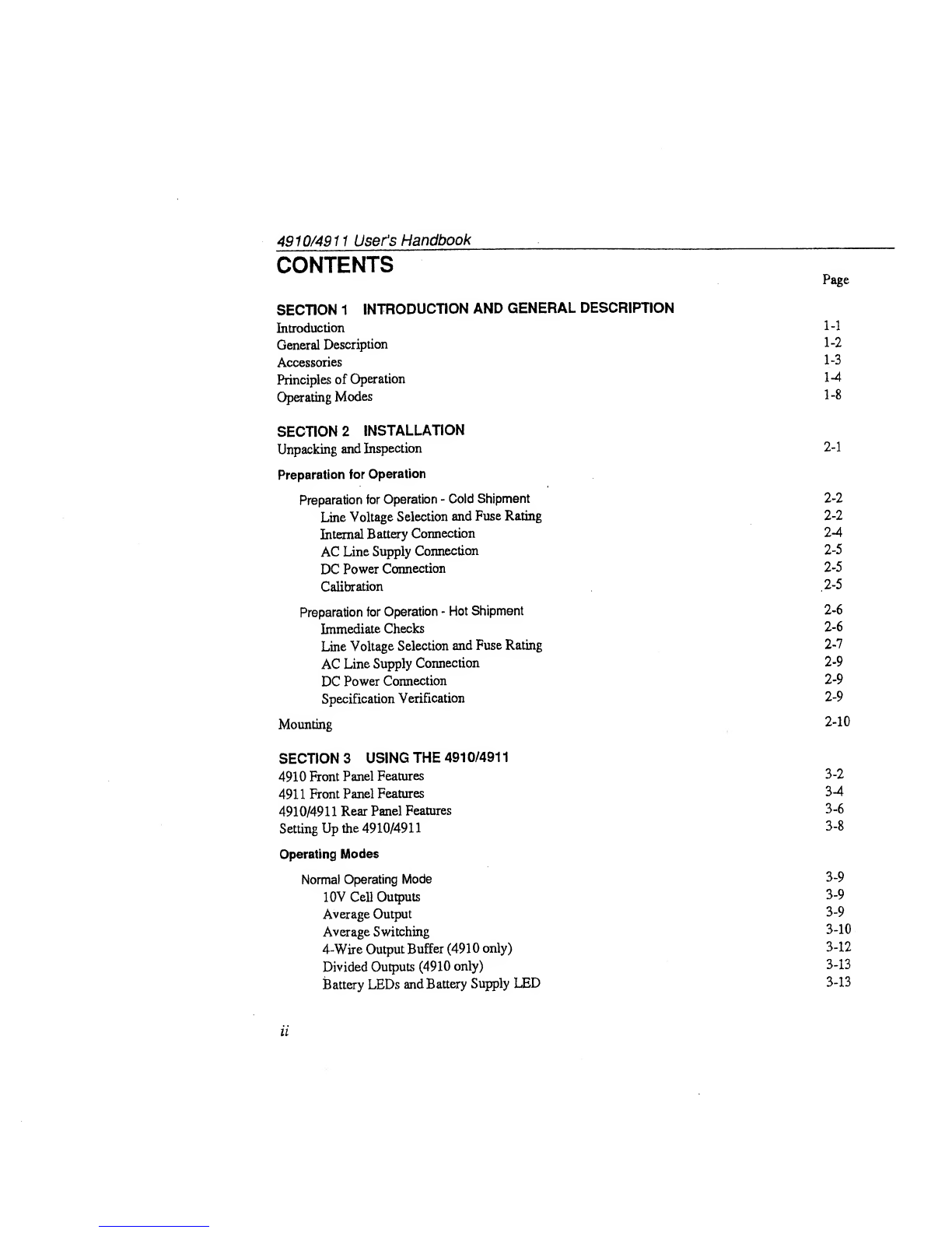
CONTENTS Page
SECTION 1INTRODUCTION AND GENERAL DESCRIPTION
Introduction 1-1
General Description 1-2
Accessories 1-3
Principles of Operation 1-4
Operating Modes 1-8
SECTION 2INSTALLATION
Unpacking and Inspection 2-1
Preparation for Operation
Preparation for Operation -Cold Shipment 2-2
Line Voltage Selection and Fuse Rating 2-2
Internal Battery Connection 2-4
AC Line Supply Connection 2-5
DC Power Connection 2-5
Calibration .2-5
Preparation for Operation -Hot Shipment 2-6
Immediate Checks 2-6
Line Voltage Selection and Fuse Rating 2-7
AC Line Supply Connection 2-9
DC Power Connection 2-9
Specification Verification 2-9
Mounting 2-10
SECTION 3USING THE 491 0/491
1
4910 Front Panel Features 3-2
491 1Front Panel Features 3-4
4910/49 11Rear Panel Features 3-6
Setting Up the 4910/4911 3-8
Operating Modes
Normal Operating Mode 3-9
10V Cell Outputs 3-9
Average Output 3-9
Average Switching 3-10
4-Wire Output Buffer (4910 only) 3-12
Divided Outputs (4910 only) 3-13
Battery LEDs and Battery Supply LED 3-13
ii

4910/4911 User's Handbook
Page
SECTION 3(Contd.)
Normal Operating Mode (Contd.)
Temp LEDs 344
Line Supply LED 3-14
Guard Terminal 3-14
Case Terminal 344
Battery/Charge Voltages 3-15
Normal/Transit Mode Switching 3-16
Transit Operating Mode 3-17
Battery LEDs 3-17
Temp LEDs 3-18
Transit/Normal Mode Switching 3-18
SECTION 4SPECIFICATIONS
General Specifications 44
Output Specifications 4-2
SECTION 5SPECIFICATION VERIFICATION AND CALIBRATION
Introduction 54
Calibration Confidence-check 5-2
Equipment Requirements 5_2
Interconnecting Leads 5_2
Null Detector Zeroing 5-3
Calibration Confidence-check Procedure 5-4
Calibration 5.9
Introduction 5-9
Equipment Requirements 5.9
Adjustment of Unit Under Test Outputs 5-10
Interconnecting Leads 5-10
Null Detector Zeroing 542
Calibration Procedure 543
Appendices:
A4910/4911 Calibration Confidence-check Report Sheet
B4910/49 11Calibration Report Sheet
CBattery Charging Voltage Limits
D4910 -Measurement of Divided Outputs
iii


Section 1_ -Intivduction and General Description
SECTION 1INTRODUCTION AND GENERAL
DESCRIPTION
Introduction
The 4910 and 4911 are Electronic DC Voltage
Reference Standards which feature four separate
and highly stable 10V outputs. While their
performance is comparable to that of saturated
Weston standard cells, they eliminate most of the
drawbacks encountered in standard cell use and
maintenance. In addition to replacing saturated
Weston cells as alaboratory standard, the 4910
and 4911 can also be used as areadily
transportable standard.
1-1

Section 1-Introduction and General Description
General Description
The 4910 and 4911 DC Voltage Standards are
based on the latest zener-diode technology. Their
four separate 10V outputs are fully independent,
but can if required be averaged to provide avery
low noise 10V output on separate front-panel
terminals. The provision of both individual and
average outputs enables direct inter-comparison
between the cells at the output terminals, allowing
excessive drift in any cell to be detected without
the use of higher accuracy standards. The
individual outputs -are adjustable to within
microvolts of one another, so that inter-
comparison is possible to avery high level of
accuracy.
In addition to its four individual cell outputs and its
average 10V output, the49 10 also features IV and
1.018V outputs, and alow-impedance 10V output
with 4-wire sensing.
In their normal operating mode, the units can be
powered from an ac line supply or from their
internal batteries. Both models also feature a
special low-powertransit mode,which can be used
during transportation or shipment of aunit to
maintain its calibration. In transit mode, power
can be derived from the unit’s internal batteries,
from an external DC supply, or from an AC line
supply.
1-2
Section l-Introduction and_ General Description
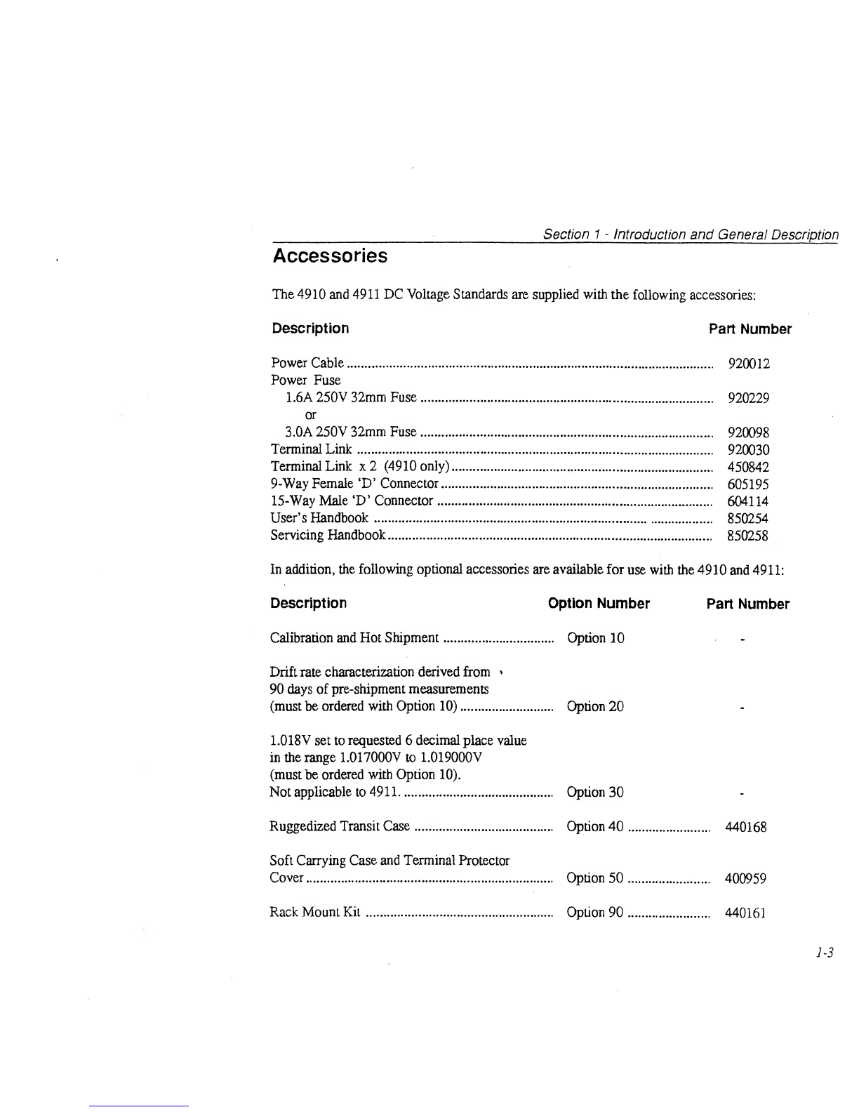
Accessories
The 4910 and 4911 DC Voltage Standards are supplied with the following accessories:
Description Part Number
Power Cable 920012
Power Fuse
1.6A250V 32mm Fuse 920229
or
3.0A 250V 32mm Fuse 920098
Terminal Link 920030
Terminal Link x2 (4910 only) 450842
9-Way Female ‘D’ Connector 605195
15-Way Male ‘D’ Connector 604114
User’s Handbook 850254
Servicing Handbook 850258
In addition, the following optional accessories are available for use with the 4910 and 4911:
Description Option Number Part Number
Calibration and Hot Shipment Option 10 -
Drift rate characterization derived from *
90 days of pre-shipment measurements
(must be ordered with Option 10) Option 20
1.018Vset to requested 6decimal place value
in the range 1.017000V to 1.019000V
(must be ordered with Option 10).
Not applicable to 49 11Option 30
Ruggedized Transit Case Option 40 440168
Soft Carrying Case and Terminal Protector
Cover Option 50 400959
Rack Mount Kit Option 90 440161
1-3

Section 1-Introduction and General Description
Principles of Operation
The 4910/4911 DC Voltage Standard is based control, the zener diodes have an on-chip
around precision zener-diode voltage references temperature compensation transistor, a
and pulse-width-modulation (PWM) voltage temperature sensing transistor and asubsirate
dividers. It is this solid-state circuitry which gives heating element —see Fig 1.1. These on-chip
the unit its portability and ease of use. components allow the chip temperature to be
stabilized to within approximately 1m°C, and by
To eliminate temperature coefficient (TC) providing direct control of the zener’s substrate
problems, the reference zener-diodes are temperature they avoid the long warm-up times
stabilized at aconstant temperature, afew °C and high power consumptions of conventional
above the instrument’s maximum ambient temperature controlled “ovens”,
operating temperature. To facilitate temperature
1-4

Section l-Introduction and_ General Description
However, precision control of the gain of A1 is
provided by the PWM divider and the high DC
gain amplifier. A2. Because the PWMdivider has
anegligble TC and ageing coefficient, it
automatically compensates for the TC and ageing
of resistors R1 and R2. As aresult the
temperatures of R1 and R2 do not need to be
controlled, as is the case for other solid state DC
voltage references. In addition, the PWM divider
can be controlled totally digitally, and therefore
contains no adjustment potentiometers which
could contribute to drift.
The zener reference produces ahighly stable
output at around 7.2V, which is amplified to
produce an accurate 10V output. Rather than
using resistors to set the gain of the amplifier,
(which would introduce unacceptable TC
problems and provide no reliable and simple
means of gain adjustment), the 4910/4911 uses a
PWMvoltage divider as the gain defining element
—see Fig 1.2. Coarse gain is controlled by
resistors R1 and R2 in adirect feedback path
around amplifier Al.
1-5
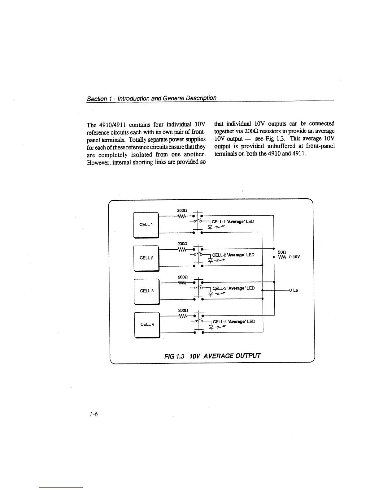
The 4910/4911 contains four individual 10V
reference circuits each with its own pair of front-
panel terminals. Totally separate power supplies
for each ofthese reference circuits ensure that they
are completely isolated from one another.
However, internal shorting links are provided so
that individual 10V outputs can be connected
together via 200£2 resistors to provide an average
10V output —see Fig 1.3. This average 10V
output is provided unbuffered at front-panel
terminals on both the 4910 and 4911.
1-6
Section 1-Introduction and General Description
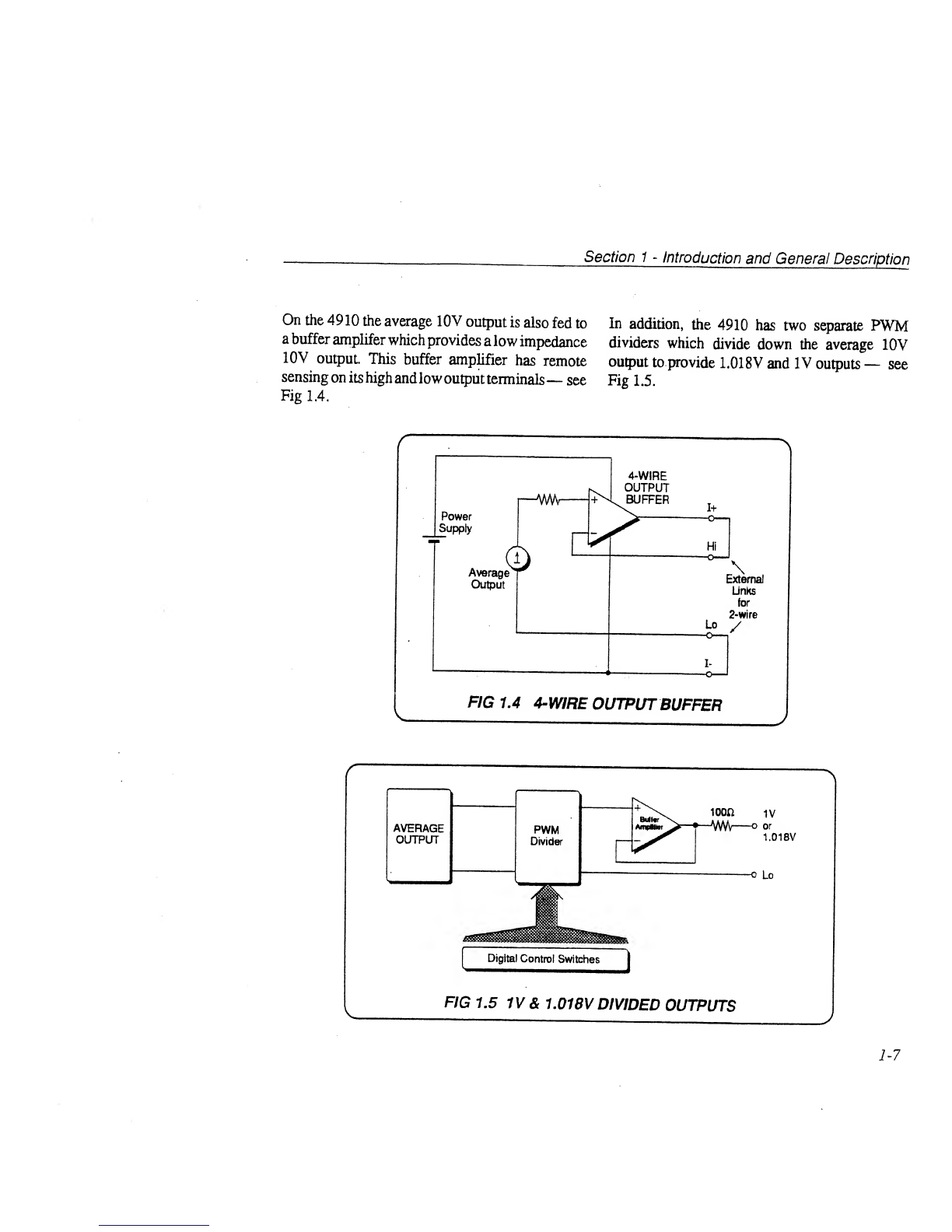
On the 4910 the average 10V output is also fed to
abuffer amplifer which provides alow impedance
10V output. This buffer amplifier has remote
sensing on its high andlowoutput terminals —see
Fig 1.4.
In addition, the 4910 has two separate PWM
dividers which divide down the average 10V
output to provide 1.018V and IV outputs —see
Fig 1.5.
1-7

Section 1-Introduction and General Description
Operating Modes
The 4910/4911 has two basic operating modes —
Normal modeand Transit mode.The Transit mode
is provided so that the unit can be shipped by
normal carrier methods, with all of its critical
circuitry powered from its internal batteries, alow
voltage external DC supply or an AC line supply.
Aswitch on the rear panel allows the unit to be
switched from one modeto the other. (CAUTION
-Read Section 3before switching the unit from
Normal to Transit mode.)
Normal Mode
In Normal mode all of the unit’s internal circuitry
is powered up and active. If its temperature in
Transit mode has been stable in an ambient
temperature of23°C ±5°C; then the unit will meet
its full output specifications within four hours of
being switched from Transit mode into Normal
mode. If it has been subjected to extremes of
temperature in transit, then alonger period will be
required.
In Normal mode the 4910/4911 can be powered
from asuitable AC line supply,or from its internal
batteries, which will maintain a4910 fully
operational for anominal period of 9hours, and a
4911 fully operational for anominal period of 17
hours.
In Normal mode, an external supply connected to
the External DC socket will be isolated.
Transit Mode
In Transit mode only the zener reference module,
zener diode tehiperature stabilization circuits and
battery monitoring circuits remain powered up
and active.
In this mode the 4910/491 1can be powered from
its internal batteries, from an external 10V to 40V
DCsupply which is capable of delivering acurrent
of at least 1A, or from asuitable AC line supply.
^Assuming that the unit’ sbatteries are initially fully
charged and that the unit remains at its specified
operating temperature of 25°C, the internal
batteries will maintain the zener diode references
at aconstant temperature for aminimum period of
168 hours (7 days). At other temperatures within
its lower operating range of 0°C to 25°C, this time
will be reduced; for instance it is estimated that at
0°C, the reduced period will be 100 hours.
1-8

Section 2-Installation
SECTION 2INSTALLATION
This section contains information and instructions for unpacking and installing the Datron 49 10 or 49 1
1
DC Voltage Reference Standard. The layouts of the instruments’ front and rear panels can be found in
Section 3.
Unpacking and Inspection
Every care is taken in the choice of packing
material to ensure that your equipment will reach
youin perfect condition. Iftheequipmenthasbeen
subject to mishandling in transit, this fact will
probably be visible as external damage to the
shipping carton. In the event of damage, the
shipping container and cushioning material
should be kept for the carrier’s inspection.
Unpack the equipment and check for external
damage to the case, sockets, front panel terminals
etc. If damageis found, notify the carrier and your
sales representative immediately.
Standard accessaries supplied with the instrument
should be as described in Section 1.
2-1
Section 2-Installation -Co/d Shipment
Preparation for Operation -Cold Shipment
(Option 10 not specified on ordering)
IMPORTANT: If the 4910/4911 was ordered
with Option 10 (Calibration and Hot
Shipment) it will have been despatched in
Transit mode, with its internal batteries
maintaining the zener references at constant
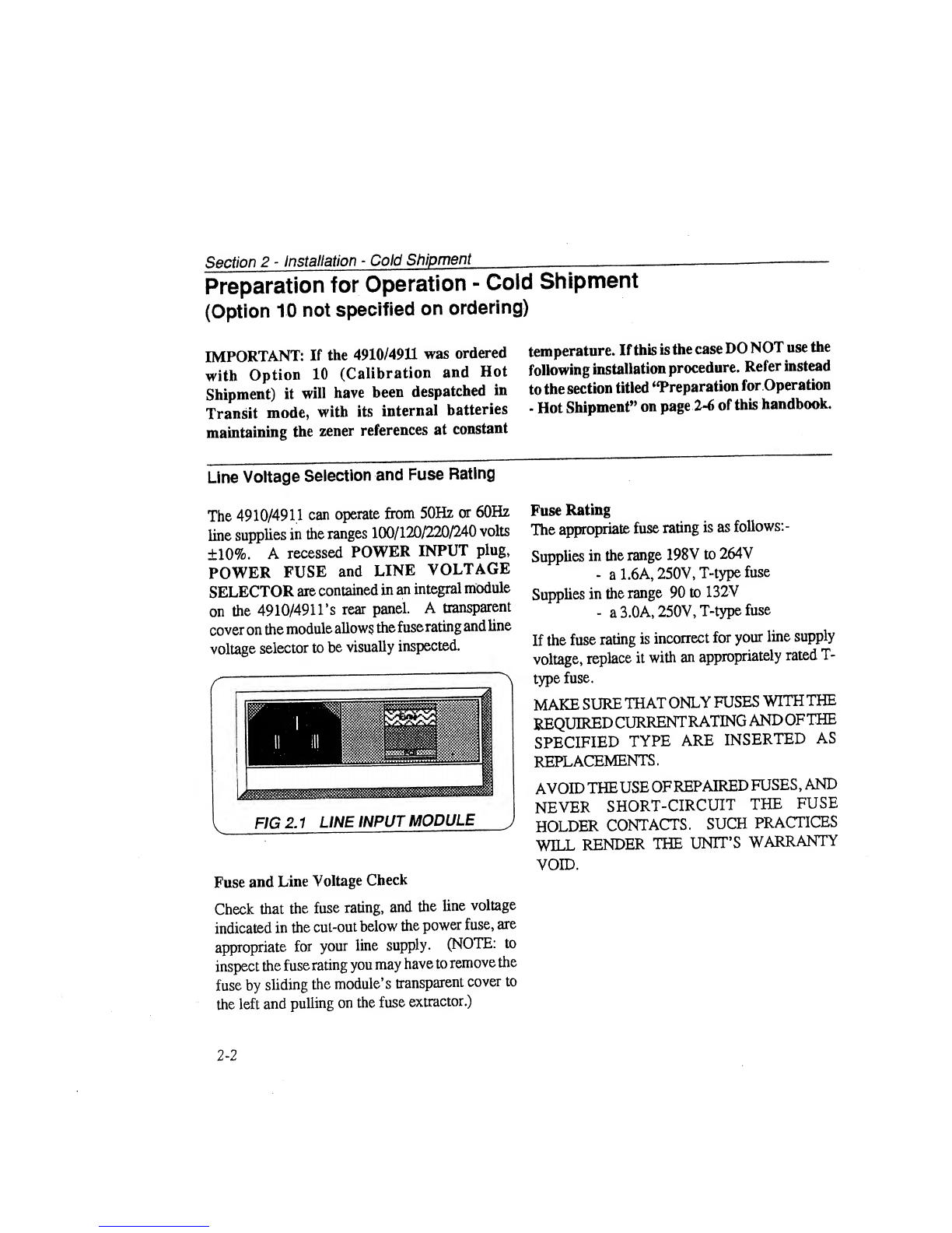
Line Voltage Selection and Fuse Rating
The 4910/4911 can operate from 50Hz or 60Hz
line supplies in the ranges 100/120/220/240 volts
±10%. Arecessed POWER INPUT plug,
POWER FUSE and LINE VOLTAGE
SELECTOR are contained in an integral module
on the 4910/491 l’s rear panel. Atransparent
cover on the module allows the fuserating and line
voltage selector to be visually inspected.
Fuse and Line Voltage Check
Check that the fuse rating, and the line voltage
indicated in the cut-out below the power fuse, are
appropriate for your line supply. (NOTE: to
inspect the fuserating you may have to remove the
fuse by sliding the module’s transparent cover to
the left and pulling on the fuse extractor.)
temperature. If this is the case DONOT use the
following installation procedure. Refer instead
to the section titled “Preparation for Operation
-Hot Shipment” on page 2-6 of this handbook.
Fuse Rating
The appropriate fuse rating is as follows: -
Supplies in the range 198Vto 264V
-a1.6A, 250V, T-type fuse
Supplies in the range 90 to 132V
-a3.0A, 250V, T-type fuse
If the fuse rating is incorrect for your line supply
voltage, replace it with an appropriately rated T-
type fuse.
MAKE SURE THATONLY FUSES WITHTHE
REQUIREDCURRENTRATING ANDOFTHE
SPECIFIED TYPE ARE INSERTED AS
REPLACEMENTS.
AVOID THEUSE OFREPAIRED FUSES,AND
NEVER SHORT-CIRCUIT THE FUSE
HOLDER CONTACTS. SUCH PRACTICES
WILL RENDER THE UNIT’S WARRANTY
VOID.
2-2

Section 2-Installation -Cold Shipment
To Reselect the Operating Voltage:
If the indicated line voltage is inappropriate for your line supply, carry out the following procedure:-
1. FIRST ensure that the POWER CABLE is
removed.
2.Slide the protective window to the left to reveal
the fuse and voltage selector pc board.
3.Draw the fuse extractor to the left, and remove
the fuse.
4. Remove the voltage selector pc board (NOTE:
ahole is provided in the board to assist in its
removal) androtate it until the appropriate line
voltage appears on the left-hand side of the
upper surface.
5. Re-insert the selector pc board firmly into its
slot in the module. The selected line voltage
should be visible in the cutout below the fuse.
6. Move the fuse extractor to the right-hand
position.
7. Insert the appropriate POWER FUSE.
8. Slide the protective window to the right.
r
FIG 2.2 LOCATION AND ORIENTATION OF
VOL TAGE SELECTOR PCB
V
{Preparation for Operation -Cold Shipment: continued overleaf)
2-3

Section 2-Installation -Cold Shipment
Internal Battery Connection
The 4910/4911 contains internal batteries which
power the unit when it is not operating from aline
supply or an external DC input. If Option 10
(Calibration and Hot Shipment) was NOT
specified on ordering the 4910/4911, the unitwill
be shipped with its internal batteries disconnected.
To Connect the Internal Battery Pack
Before connecting the unit to aline supply or
external DC power source, carry out the following
procedure: -
1. Ensure that the rear-panelBATTERYMODE
switch is switched to N(Normal) position.
2. Remove the two screws situated towards the
rear of the unit’s top cover and remove the top
cover.
3. Detach the battery connecting plug (P102)
from its retaining clip on the outside of theLine
Input Unit (position 'B 'in Fig. 2.3) and insert it
into its socket (J 102) on the rear of the Battery
Pack (position 'A' in Fig. 2.3).
4. Check that the four Battery LEDs situated
above the CELL outputs, and the Battery
Supply LED situated above the AVERAGE
output, are continuously lit GREEN or are
flashing between RED and GREEN. If any of
these LEDs are continuously RED, flashing
RED, or permanently OFF the unit probably
has afault, in which case you shouldrefer to the
4910/4911 Servicing Handbook or contact
your local service center.
5. Leave the unit to warm up for 5minutes.
6. Press the HEATER RESET pushbutton
which is recessed into the rear panel of the unit.
7.Check that all of the Temp LEDs on the unit’
s
front panel are lit GREEN. (If any ofthe Temp
LEDs is not lit GREEN immediately after
pressing the HEATER RESET pushbutton,
the unit probably has afault, in which case
consult the 4910/49 11Servicing Handbook or
your local service center.)
8. Replace the unit’s top cover and the two top
,cover retaining screws.
2-4
Section2-Installation -Cold Shipment
AC Line Supply Connection
The detachable AC POWER CABLE comprises
two metres of 3-core PVC sheathed cable
permanently moulded to afully-shrouded 3-pin
cable socket. It fits into the receptacle in the
POWER INPUT moduleon the unit’ srear panel,
and should be pushed firmly home. The power
cable should be connected to agrounded line
supply outlet. When connecting the cable to a
suitable line plug, connectthe Brown lead to Line,
Blue lead to Neutral, and Green/Yellow lead to
Ground. DO NOT operate the unit from an
ungrounded line supply, and NEVER disconnect
the ground lead in the power cable’s line plug.
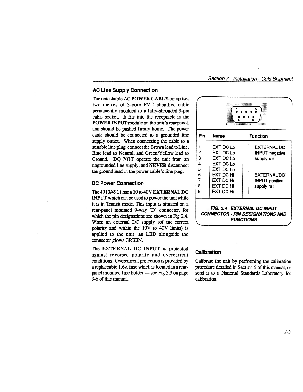
DC Power Connection
The 4910/49 11has a 10 to 40V EXTERNAL DC
INPUT which can be used to power the unit while
it is in Transit mode. This input is situated on a
rear-panel mounted 9-way ‘D’ connector, for
which the pin designations are shown in Fig 2.4.
When an external DC supply (of the correct
polarity and within the 10V to 40V limits) is
applied to the unit, an LED alongside the
connector glows GREEN.
The EXTERNAL DC INPUT is protected
against reversed polarity and overcurrent
conditions. Overcuirent protection is provided by
areplaceable 1.6A fuse which is located in arear-
panel mounted fuse holder —see Fig 3.3 on page
3-6 of this manual.
Calibration
Calibrate the unit by performing the calibration
procedure detailed in Section 5of this manual, or
send it to aNational Standards Laboratory for
calibration.
2-5

Section 2-Installation -Hot Shipment
Preparation for Operation -Hot Shipment
(Option 10 specified on ordering)
IMPORTANT: If the 4910/4911 was ordered Refer instead to the section titled “Preparation
without Option 10 (Calibration and Hot for Operation -Cold Shipment” on page 2-2 of
Shipment) DO NOT use the following this handbook,
installation procedure.
Immediate Checks
Immediately after unpacking a4910/4911 which
was ordered with Option 10 (Calibration and Hot
Shipment) carry out the following procedure:
1. Checkthat the calibration seals are notbroken.
2. Move the 4910/4911 to astable environment
which meets the environmental specifications
detailed in Section 4of this manual.
3. Check the unit’s front panel LEDs to ensure
that they are in the following condition.
(NOTE: because the front-panel LEDs are
strobed in Transit mode to conserve battery
power, an individual LED must be observed
for at least 30 seconds to determine its true
condition.) :-
Cell 1, 2, 3and 4Battery LEDs:
flashing GREEN or flashing RED and
GREEN (see NOTE below).
Cell 1, 2, 3and 4Temp LEDs:
flashing GREEN.
If any ofthese LEDsis in acondition other than the
ones listed above, the unit may have been in
Transit mode for longer than seven days, or may
have been subjected to extremes of temperature.
Contact Datron Instruments or your supplier.
NOTE:
If any of the Cell 1, 2, 3and 4Battery LEDs is
flashing RED and GREEN it indicates that the
unit’s internal batteries require recharging. There
shouldbeas little delay aspossiblebefore carrying
out the remainder ofthe installation procedure and
connecting the unit to an AC line supply or
external DC supply if it is to remain in Transit
mode, or to an ACline supply ifit is to be switched
to Normal mode.
2-6
This manual suits for next models
1
Table of contents
Other Datron Batteries Charger manuals


