newmotion Home Standard 2.1 User manual
100 cm
Home Standard 2.1 3,7 kW
Home Fast 2.1 3,7 - 22 kW
VERSION 0381NM02INT02 2019
INSTRUCTION MANUAL – EN | INSTALLATIEHANDLEIDING – NL | INSTALLATIONSANLEITUNG - DE | MANUEL D’INSTALLATION - FR


NewMotion
Home Standard 2.1 3,7 kW
Home Fast 2.1 3,7 - 22 kW
NL: +31 (0)88 010 9500
BE: +32 (0)2 588 1251
DE: +49 (0)30 215 028 48
FR : +33 (0)9 77 55 43 49
UK: +44 (0)203 868 1036
Instruction manual (EN)
Pages 4 - 16
Installatiehandleiding (NL)
Pagina 17 - 29
Installationsanleitung (DE)
Pagina 30 - 42
Manuel d’installation (FR)
Page 43 - 55
Table of contents / Inhoudsopgave /
Inhaltsverzeichnis / Table des matières

INSTALLATIEHANDLEIDING – P4 VERSION 0129NM02INT01INSTRUCTION MANUAL – P4 | P4 0381NM02INT02
EN NL DE FR
1.1 PRODUCT DESCRIPTION &
INTENDED USE
Thank you for choosing a NewMotion Electric Vehicle
(EV) Charge Point.
This charge point is intended to charge the batteries within
EVs compatible with IEC-61851 MODE3 denition and
requirements. Dedicated EV specic plugs will need to be
utilised. No adaptors, conversion adaptors or extension
sets for cables are allowed to be used. EVs and cables
used with this charge point should always be undamaged
and in their original state.
1.2 SAFETY WARNING + CAUTION!
The electrical system must be voltage-free during the
entire installation procedure. Failing to do so can lead to
serious injury or even death. The installation procedure
must be carried out by a trained electrician who works in
accordance with all relevant local laws and regulations.
Do not install in potentially explosive atmospheres and/
or zones with high electromagnetic radiation and/or
in ood-prone areas. The charge point is connected
to the electricity grid and even if the equipment is
switched o, hazardous voltages may be present at
the input terminals. Always switch o the AC supply
before starting any work on the charge point and/or its
installation. Do not carry out any work in rainy conditions
or when the humidity is above 95%. The safety
guidelines are intended to ensure correct installation
and usage. Any failure to comply with the valid safety
guidelines or instructions provided in this manual may
result in re, electrocution or severe injury.
The charge point is a product in Safety Class I and is
supplied with an earth terminal for protection purposes.
The AC input clamps must be tted with an uninterruptible
earth for protection purposes. Ensure that the connection
cables are tted with fuses and circuit breakers. Never
replace a protection component with another type. First
check the full installation to determine if that component
can be used with the existing installation components.
Before you switch on the charge point, check that
the available power source matches the conguration
settings of the product, as described in this manual.
Tripping of the RCD could be caused by an earth fault
or a defect relay. If, after resetting the RCD, the device
cannot be activated or immediately trips again; please
contact NewMotion or your installer.
1.3 LEGAL DISCLAIMER
This manual is created for you with care.
We however do not guarantee that all information is
complete, accurate and correct. Please check our
website www.newmotion.com for the latest version
of this manual. We strongly advise you to have our
product installed by certied professionals. How our
product should be installed and used depends on
local circumstances and local and national regulation,
which are not mentioned in our manual. NewMotion
is not responsible for any loss or damage whatsoever
caused - including without limitation, any indirect,
personal or consequential loss or damage – arising
from or in connection with the use of this manual. Nor
does NewMotion accept any liability for any such loss or
damage arising out of your reliance on any information
contained in this manual.
1. INTRODUCTION

INSTALLATIEHANDLEIDING – P5 VERSION 0129NM02INT01INSTRUCTION MANUAL – P5 | P5 0381NM02INT02
EN NL DE FR
To ensure the charge point is ready for use, the owner
needs to activate the charge point through our online por-
tal at my.newmotion.com. The serial number of the charge
point is needed for this process which can be found on
the right hand side of the charge point. Charge cards can
be activated in the same online portal.
2. ACTIVATING CHARGE POINT BEFORE USE

INSTALLATIEHANDLEIDING – P6 VERSION 0129NM02INT01INSTRUCTION MANUAL – P6 | P6 0381NM02INT02
EN NL DE FR
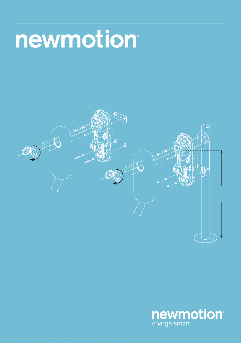
Way of mounting
Standard: charge
point wall bracket
mounting
Optional pole
mounting
Optional concrete
base (for in soil) for
pole
Optional Wall bracket
for two NewMotion
charge points
Required tools & additional materials
(not provided)
- Installation materials (power cable and
cable mount clips, RCD(‘s), MCB(‘s), etc);
- Network switch (optional and not sold
by NewMotion);
- UTP cable(s) (CAT5 or CAT6);
- RJ45 UTP cable crimp tool;
- RJ45 connectors;
- 4 x screws (at least 6.3 x 60/70) and
plugs for mounting in wall;
- Drill and bit;
- Torx screwdrivers (T20 and T45);
- Voltage tester;
- Tape measure;
- Spirit level;
- All mentioned for standard mounting,
plus;
- Pole (sold separately);
- 4 x M8 wedge bolts or chemical
anchors, plus nuts and washers;
- All mentioned for pole mounting, plus;
- Concrete base (sold separately);
- DIN 912 HEX allen key (Size 6);
- Shovel;
- All mentioned for standard mounting,
plus;
- Pole (sold separately);
Package contents charge point
- Charge point;
- Wall bracket;
- Rubber grommets (various sizes);
- 2 x plastic spacers;
- Sticker sheet for the sides of the
charge point;
- 1 x M4 x 20 mm bolt (Torx);
- 6 x M4 x 12 mm bolts (Torx);
- 2 x M8 x 12 mm bolts (Torx);
- 4 x M8 x 12 mm bolts (Torx) plus
washers;
- 4 x M8 x 35 mm bolts (HEX DIN 912)
plus washers;
- 4 x M8 x 12 mm bolts (Torx) plus
washers;
3. PRODUCT OVERVIEW
3.1 MOUNTING OPTIONS, PACKAGE CONTENTS AND REQUIRED TOOLS

INSTALLATIEHANDLEIDING – P7 VERSION 0129NM02INT01INSTRUCTION MANUAL – P7 | P7 0381NM02INT02
EN NL DE FR
3.2 TECHNICAL SPECIFICATIONS
3. PRODUCT OVERVIEW
CONTINUED ON NEXT PAGE
Serial number format Home Standard
Serial number format Home Fast
Maximum charge capacity
Standard congured charge capacity
Electric safety category
DC-fault current protection
Dimensions (H x W x D)
Weight
Standard colours
IEC-62262 IK code (robustness)
IEC-60529 IP code (protection class)
Certicates
kWh measurement
User interface
Identication
Communication backoce
051 _ _ _ _ _
061 _ _ _ _ _
Home Standard 1-phase 16A (3,7 kW)*
Home Fast 1-phase 32A (7,4 kW)*
Home Fast 3-phase 32A (22 kW)*
Home Standard 1-phase 16A (3,7 kW)
Home Fast 1-phase 16A (3,7 kW)**
Home Fast 3-phase 16A (11 kW)**
Class 1
Built-in 6mA DC fault current protection
503.5 x 200 x 137 mm
± 3.5 kg
Rear side RAL 7031 (grey)
Front side RAL 9010 (white)
IK10
IP54 (for indoor and outdoor use)
IEC-61851-1
IEC-61851-22
EV-Ready & ZE-Ready
IEC-62262 -> IK10
IEC-60529 -> IP54
IEC-62955 -> 6mA DC-fault protection
via Current Transformers (CT)
LED
Plug & Charge
Ethernet connection (DHCP, TCP 443, TCP80, TCP21)
GPRS 2/3/4G with mobile router***

INSTALLATIEHANDLEIDING – P8 VERSION 0129NM02INT01INSTRUCTION MANUAL – P8 | P8 0381NM02INT02
EN NL DE FR
* The maximum charge capacity of the charge point depends on several factors. This includes; local rules &
regulations, the type of EV, the grid connection at your location and the electricity usage of your building.
**Contact NewMotion for changing charge capacity
***Contact NewMotion for further information: +44 20 3868 1036 and press option 1.
3.2 TECHNICAL SPECIFICATIONS
3. PRODUCT OVERVIEW
Backoce protocol
Stand-by consumption
Operating temperature range
Operating humidity range
Operating air pressure range
Maximum mounting height socket
Advised mounting height socket
Mounting position
Function for ventilation according to IEC-61851
OCPP protocol
3-5W
-30℃ to +50℃
5% to 95%
860 hPa to 1060 hPa
1.5 meter above ground
1 meter above ground
Vertical and upright position only
Not supported

INSTALLATIEHANDLEIDING – P9 VERSION 0129NM02INT01INSTRUCTION MANUAL – P9 | P9 0381NM02INT02
EN NL DE FR
3.3 OVERVIEW OF PRODUCT
3. PRODUCT OVERVIEW
Type 2 EV Plug
socket & Cover lid
or dummy socket
Identication label
with serialnumber
Product details
LED status indicator
INSTALLATIEHANDLEIDING – P10 VERSION 0129NM02INT01INSTRUCTION MANUAL – P10 | P10 0381NM02INT02
EN NL DE FR
3. PRODUCT OVERVIEW
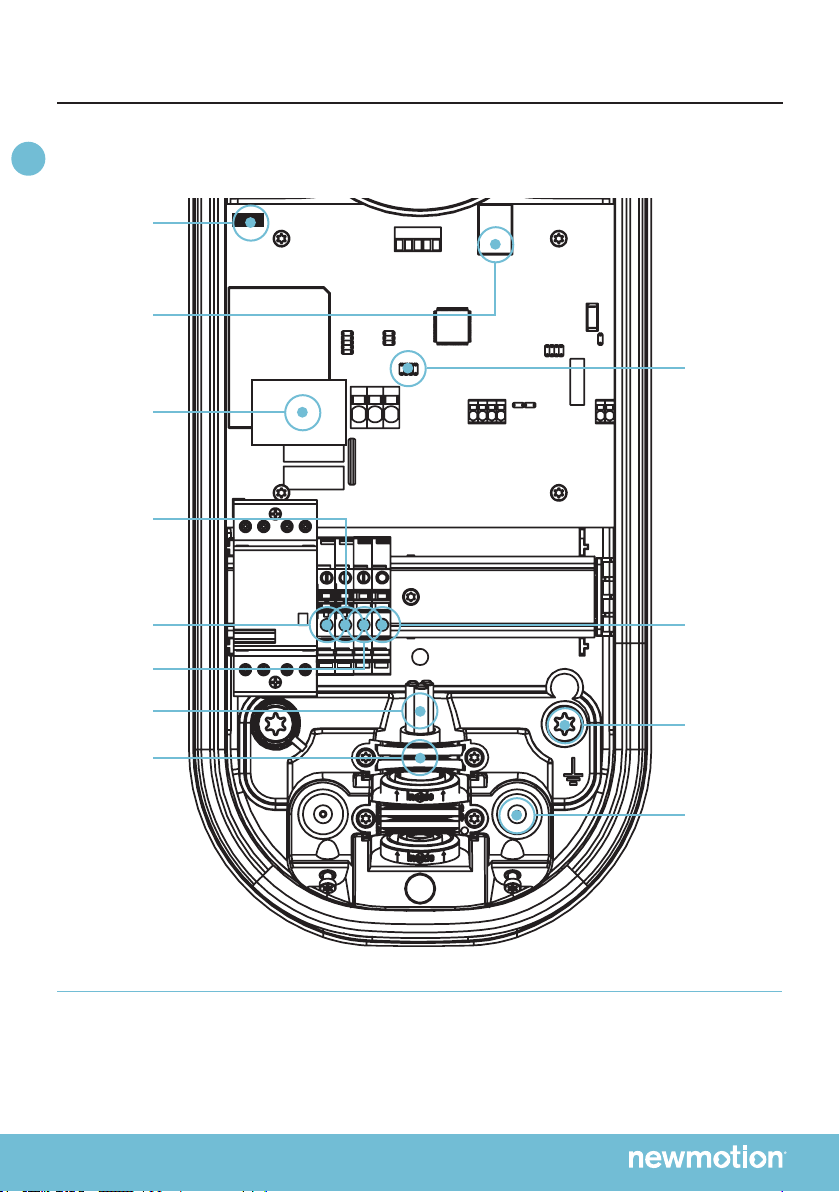
3.4 OVERVIEW OF CONNECTIONS
neutral wire
connection
phase wire
connection
earth wire
connection
power cable
cable clamp
earthing pole
connection
earthing
pole
inlet for
data cable
Dip switches for
settings
If connecting to a 3-phase grid without neutral; only install 1-phase and connect one of the two other phase wires
in the neutral wire connection on the terminal block.
DC-fault
protection
module
DC-fault
protection
connection
ethernet port
INSTALLATIEHANDLEIDING – P11 VERSION 0129NM02INT01INSTRUCTION MANUAL – P11 | P11 0381NM02INT02
EN NL DE FR
3. PRODUCT OVERVIEW
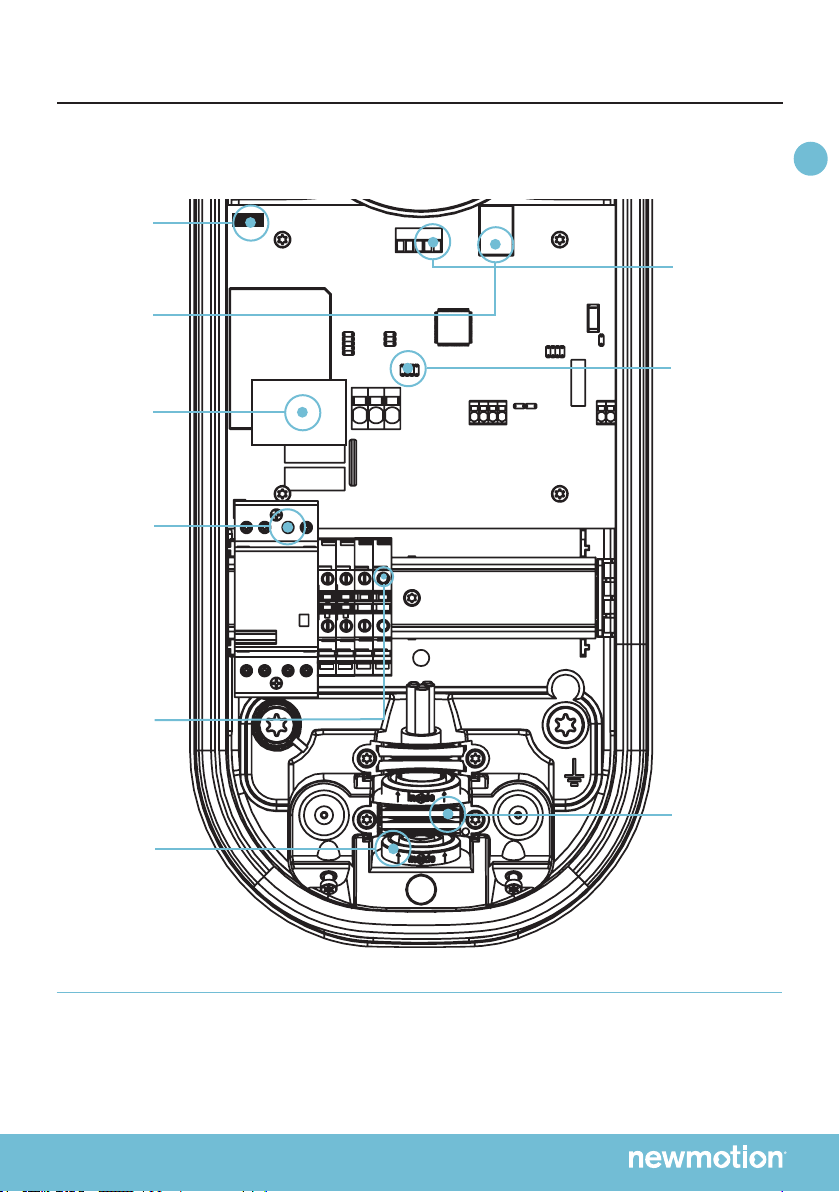
OVERVIEW TETHERED CABLE*
connector
for communication
with the car
at connector ‘CP’
cable clamp
tethered cable
inlet
tethered cable
connection
Keep the same
order as the
connection under
relay
L1 = portal 1
L2 = portal 3
L3 = portal 5
Neutral = portal 7
Earthing
tethered cable
Dip switches for
settings
Placement tethered cable
When installation is complete, place the plug of the cable in the designated dummy socket on the charge point.
Caution: The Phase 1 (Brown), Phase 2 (Black), Phase 3 (Grey) and Neutral (Blue) wires of the xed cable must go
through the DC-protection module. Failing to do so will result in no protection against DC-fault currents
DC-fault
protection
module
DC-fault
protection
connection
ethernet port
INSTALLATIEHANDLEIDING – P12 VERSION 0129NM02INT01INSTRUCTION MANUAL – P12 | P12 0381NM02INT02
EN NL DE FR
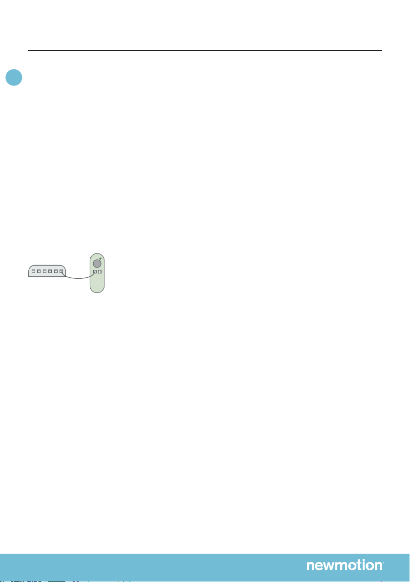
3.5 BACKOFFICE CONNECTIONS
The Home Standard & Home Fast can be connected to
the NewMotion backoce in two ways:
1. Ethernet connection
2. 2/3/4G with NewMotion mobile router
The Home Standard & Home Fast will connect to the
NewMotion backoce so settings can be changed
remotely and for remote support to be given. Without the
backoce connection, none of our online services can
be used.
3.5.1 HOME STANDARD & HOME FAST –
ETHERNET / NEWMOTION MOBILE ROUTER
Connecting the Home Standard & Home Fast to an
ethernet or mobile router can be done by connecting the
network to the UTP Ethernet data port with a cable max
50 meter long.
Settings might have to be changed in the network to
allow the charge point to make a successful connection
to the NewMotion backoce.
The network should have:
- DHCP
- Port TCP 80 and 443 should be opened
- FTP port 21 should be opened
- All opened ports should be inbound and outbound
- No proxy or socks server connection
FTP is needed to update the rmware of the chargepoint
and exchange diagnostics.
3. PRODUCT OVERVIEW
(Mobile)
Router

INSTALLATIEHANDLEIDING – P13 VERSION 0129NM02INT01INSTRUCTION MANUAL – P13 | P13 0381NM02INT02
EN NL DE FR
Wiring advice*
Power cable size
Earthing advice*
Required nominal
input voltage @
charge point
MCB
RCD
Ethernet connection
cable requirements
Ø 10mm - Ø 22,5mm
10mm2 solid wire
6mm2 stranded wire with end ferrules
PE-cable (Pen conductor is not allowed)
Separately installed grounding electrode < 100
Ohm spreading resistance
230V +/-10% 50Hz
400V (3 x 230V+N) +/-10% 50Hz
Cable grommets sizes
Maximum cable terminal block
TN-system
TT-system
Single phase**
Triple phase**
4. INSTALLATION ADVICE
The electrician is responsible for selecting a cable thickness & safety components appropriate
for the specic situation and according to regulations;
* The electrician is always responsible for selecting a cable thickness appropriate for the specic
situation and according to regulations;
** 3-phase charge point can also be connected to 1-phase. In this case the charge point can only
charge on 1-phase;
*** The electrician must select a suitable MCB to match the amperage setting of the charge point,
taking into account MCB manufacturer specications;
NOTE: The charge point can be set between 10 A and 16 A / 32 A (depending on version);
- Wire for the maximum hardware amperage under continuous load;
- Calculate with a COS-Phi of 0.8;
- Calculate with a max allowable voltage drop over the cable of 2%;
- Use shielded cable for underground wiring;
C-characteristic***
30 mA Type A (HI, HPI, SI, KV), or 30 mA type B
Standard CAT5 or CAT6 Ethernet cable (UTP cable with RJ45 connectors)

INSTALLATIEHANDLEIDING – P14 VERSION 0129NM02INT01INSTRUCTION MANUAL – P14 | P14 0381NM02INT02
EN NL DE FR
Thank you for installing this charge point.
Make sure there is enough space to properly do the work.
Ensure to work safely and take the safety of others into
consideration as well, always work according local
safety regulations.
When selecting the mounting location of the charge point,
ensure that future maintenance work can be done easily.
5.1 PREPARATION
Step 1; Prepare the cabling & RCD and MCB (conform to
local rules & regulations);
Step 2; Indicate which circuit(s) the charge point is
connected to the distribution board;
Step 3; Attach the appropriate stickers provided
(1-phase or 3-phase) to the sides of the charge point in
the designated indent spaces;
Step 4; Turn the socket lid or dummy socket anti-clockwise
and out of the cover of the charge point;
Step 5; Then pull the cover from the rear edge to open the
charge point. Do not use any objects or tools to do this;
5.2 MECHANICAL MOUNT
For standard wall mount proceed with 5.2a, for optional
pole mount on pavement proceed with 5.2b, for optional
pole mount in soil proceed with 5.2c;
5.2A MECHANICAL MOUNT (WALL)
Step 1; Attach the wall bracket at the desired height
(+/- 1 m height) on the wall;
Step 2; Put the charge point on the wall bracket to
check its placement. On the wall, mark the positioning
of the bottom two attachment points of the charge point
and select the appropriate xtures (plugs, screws and
washers).
Step 3; Secure the charge point to the wall bracket using
the two M8 x 12 mm bolts and washers provided.
Step 4; Secure the charge point to the wall using the
bottom two attachment points. Ensure that the grey
spacers are placed on the back of the charge point at
the bottom two attachment points.
5.2B MECHANICAL MOUNT (POLE ON
PAVEMENT)
Step 1; Drill holes into the pavement for the wedge bolts
or chemical anchors (not provided);
Step 2; Route the power cable(s) and UTP cable(s)
through the pole;
Step 3; Mount the wedge bolts or chemical anchor into
the pavement;
Step 4; Mount the pole to the threaded ends with
washers and nuts (not provided);
Step 5; Mount the green/yellow pole earthing wire to the
terminal block earthing connection;
Step 6; Secure the charge point to the pole bracket
using the four M8 x 12mm bolts and washers provided,
making sure to connect the pole earthing wire to the
bottom right bolt;
5.2C MECHANICAL MOUNT (POLE IN SOIL WITH
CONCRETE BASE)
Step 1; Dig the concrete base into the soil, make sure it
is steady and level;
Step 2; Route the power cable(s) and UTP cable(s)
through the pole;
Step 3; Mount the pole to the concrete base with the 4
bolts M8 x 35 and washers that are provided;
Step 4; Mount the green/yellow pole earthing wire to the
terminal block earthing connection;
Step 5; Secure the charge point to the pole bracket
using the four M8 x 12mm bolts and washers provided,
making sure to connect the pole earthing wire to the
bottom right bolt;
5.3 POWER CONNECTION
Step 1; Select the appropriate grommet(s) that suits
the cable(s) thickness and place it in the opening of the
power cable inlet. Moisten if necessary to make it easier
to feed the power cable through;
Step 2; Secure the power cable(s) using the cable
clamp(s);
Step 3; Mount the (closed) black grommet in the
remaining cable inlet to make the charge point watertight
(not applicable for tethered cable versions);
Step 4; Connect the power to the terminal blocks, like
indicated in the ‘overview of connections’ section;
5. INSTALLATION PROCEDURE

INSTALLATIEHANDLEIDING – P15 VERSION 0129NM02INT01INSTRUCTION MANUAL – P15 | P15 0381NM02INT02
EN NL DE FR
5.4 OPTIONAL TETHERED CABLE
Step 1; Select the appropriate grommet to suit the cable
thickness and place it in the opening of the power cable
inlet. Moisten if necessary to make it easier to feed the
power cable through;
Step 2; Detach the DC protection module and carefully
put the Phase wires (Brown, Black and Grey) and
Neutral (Blue) of the tethered cable one by one through
the module.
Step 3; Connect the tethered cable wires on the relays
like indicated in the ‘overview tethered cable’ section;
Step 4; Connect the ground wire of the tethered cable to
the terminal block
Step 5; Connect the car-communication wire (red wire)
like indicated in the ‘overview tethered cable’ section;
Step 6; Take the DC-protection module and attach the
DC-protection module cable to the PCB
5.5A COMMUNICATION CONNECTION(S) (UTP)
Step 1; Feed the UTP cable(s) through the rubber
stop(s) on the data cable inlet and then connect it to
the Ethernet port(s), like indicated in the ‘overview of
connections’ section;
Step 2; Connect the UTP to an internet enabled router
with DHCP;
5.6 FINISHING UP (CLOSE
ENCLOSURE)
Step 1; Check and make sure that the rubber seal is
properly in place on the edge;
Step 2; Place the cover on the charge point;
Step 3; Hand-tighten the four M4 x 12mm bolts provided
around the socket so that the cover closes on the rubber
seal but the rubber seal does not deform;
Step 4; Hand-tighten the other two M4 x 12mm bolts
provided in the bottom of the cover;
Step 5; Turn the socket lid or dummy socket clockwise
in the cover and hand-tighten the M4 x 20mm bolt
provided;
Step 6; Switch on power to the charge point;
Step 7; Wait until charge point is fully started up (+/-10
minutes, LED should be o);
Step 8; Check that the charge point is connected to the
network. A quick check can be done via chargeportal.
newmotion.com/test. Simply enter the serial number
into the search eld and click “Search”. “Online” should
appear after the serial number. If “Online” does not
appear, check whether the charge point is properly
connected and try again. For persistent issues, please
contact NewMotion.
Step 9; Standard hardware setting is 16A. For 32A
hardware setting switch jumper positions like indicated
below in ‘DIP SWITCH INSTRUCTION’. If conguration
of charge point power settings is needed (for example
lower Amp settings) please contact NewMotion;
5. INSTALLATION PROCEDURE

INSTALLATIEHANDLEIDING – P16 VERSION 0129NM02INT01INSTRUCTION MANUAL – P16 | P16 0381NM02INT02
EN NL DE FR
6.1 BEFORE USE: ACTIVATION &
REGISTRATION
To make the charge point ready for use the owner needs
to activate the charge point through our online portal
my.newmotion.com. The serial number of the charge
point is required for this process and can be found on the
right hand side of the chargepoint. Charge cards can be
activated in the same online portal.
6.2 REGULAR USE
Introduction to charging your EV:
First step is to connect your car to the charge point by
plugging in the charge cable.
Because you are using Plug&Charge the session will
start automatically.
When the car has delayed charging congured, the LED
will remain green, until charging can start from car and
charge point.
Start charging? Plug in
Stop charging? Unplug
Full or waiting to charge
Plug in or identify
Charging
Not accepted
Error
Flashing green or multi colors: starting procedure or
software update procedure for charge point.
6. PRODUCT USE / OPERATION

INSTALLATIEHANDLEIDING – P17 VERSION 0129NM02INT01INSTALLATIEHANDLEIDING – P17 | P17 0381NM02INT02
EN NL DE FR
1.1 PRODUCTBESCHRIJVING EN
BEOOGD GEBRUIK
Bedankt voor het kiezen van een NewMotion-laadpunt
voor elektrische voertuigen.
Dit laadpunt is bedoeld om de batterijen op te laden
van elektrische voertuigen die compatibel zijn met
de denitie en vereisten volgens IEC-61851 MODE3.
Voor gebruik van dit laadpunt dient u speciale EV-
stekkers te gebruiken. Installeer het apparaat niet in
explosiegevaarlijke omgevingen en/of zones met een
hoge elektromagnetische straling en/of in omgevingen
met kans op overstromingen. De elektrische voertuigen
en kabels die u aansluit op dit laadpunt moeten altijd
onbeschadigd zijn en in de oorspronkelijke staat
verkeren.
1.2 VEILIGHEIDSWAARSCHUWINGEN
EN VOORZORGEN!
De elektrische installatie dient spanningsloos te zijn
gedurende de gehele installatieprocedure. Als dit niet het
geval is, kan dit leiden tot ernstig letsel of zelfs de dood.
De installatieprocedure moet worden uitgevoerd
door een deskundig elektromonteur die werkt
overeenkomstig alle relevante lokale wetten
en voorschriften. Installeer het apparaat niet in
explosiegevaarlijke omgevingen en/of zones met een
hoge elektromagnetische straling en/of in omgevingen
met kans op overstromingen.
Zelfs wanneer uitgeschakeld is het laadpunt aangesloten
op het elektriciteitsnet en daardoor kunnen gevaarlijke
spanningen aanwezig zijn bij de ingangsklemmen.
Schakel de netspanning altijd uit voordat u begint met
werkzaamheden aan het laadpunt of de installatie.
Voer geen werkzaamheden uit in regenachtige
weersomstandigheden of bij een luchtvochtigheid van
boven de 95%. De veiligheidsvoorschriften zijn bedoeld
om correcte installatie en gebruik te garanderen. Elke
inbreuk op de geldende veiligheidsvoorschriften of
instructies in deze handleiding kan leiden tot brand,
elektrocutie of ernstig letsel.
Het laadpunt is een product uit veiligheidsklasse I en
wordt geleverd met een aardklem ter beveiliging. De
ingangsklemmen van het elektriciteitsnet moeten zijn
voorzien van een onderbrekingsvrije massa-aansluiting
ter beveiliging. Zorg dat de aansluitkabels zijn voorzien
van zekeringen en overstroombeveiligingen. Vervang
een beveiligingsonderdeel nooit door een onderdeel van
een ander type. Controleer eerst de volledige installatie
om te bepalen of het onderdeel kan worden gebruikt
in combinatie met de bestaande componenten van de
installatie.
Controleer voordat u het laadpunt inschakelt of
de beschikbare spanningsbron overeenkomt met
de conguratie-instellingen van het product zoals
beschreven in deze handleiding.
Het activeren van de aardlekbeveiliging kan veroorzaakt
worden door een defect in de massa-aansluiting
of een defect relais. Als na het resetten van de
aardlekbeveiliging het apparaat niet kan worden
geactiveerd of de aardlekbeveiliging onmiddellijk
weer wordt geactiveerd, neem dan contact op met
NewMotion of uw installateur.
1.3 JURIDISCHE DISCLAIMER
Deze handleiding is voor u met zorg samengesteld.
Wij garanderen echter niet dat alle informatie volledig,
accuraat en juist is. Ga naar onze website
www.newmotion.com voor de nieuwste versie van
deze handleiding. Wij raden u sterk aan om ons product
te laten installeren door gecerticeerde professionals.
Hoe ons product moet worden geïnstalleerd en gebruikt
hangt af van de plaatselijke omstandigheden en lokale
en nationale regelgeving die niet in onze handleiding
vermeld staan. NewMotion is niet verantwoordelijk voor
enig verlies of schade - met inbegrip van, maar niet
beperkt tot - indirecte, persoonlijke of gevolgschade
- voortvloeiend uit of in verband met het gebruik van
deze handleiding. Evenmin aanvaardt NewMotion enige
aansprakelijkheid voor dergelijke schade of verlies die
het gevolg is van uw vertrouwen op enige informatie in
deze handleiding.
1. INLEIDING

INSTALLATIEHANDLEIDING – P18 VERSION 0129NM02INT01INSTALLATIEHANDLEIDING – P18 | P18 0381NM02INT02
EN NL DE FR
Om het laadpunt gebruiksklaar te maken, dient de
eigenaar het laadpunt te activeren in onze online portal
op my.newmotion.com. Deze procedure vereist het
serienummer van het laadpunt welke vermeld staat op
de rechterzijde van het laadpunt.Laadpassen kunnen
via dezelfde online portal worden geactiveerd.
2. ACTIVEREN EN REGISTREREN

INSTALLATIEHANDLEIDING – P19 VERSION 0129NM02INT01INSTALLATIEHANDLEIDING – P19 | P19 0381NM02INT02
EN NL DE FR
3. PRODUCTOVERZICHT
Wijze van montage
Standaard: laadpunt
montage met
muurbeugel
Optionele
paalmontage
Optionele betonvoet
(voor plaatsing
in de grond) voor
paalmontage
Optionele
muurbeugel voor
twee NewMotion
laadpunten
Benodigde gereedschappen en
materialen (niet meegeleverd)
- Installatiematerialen (voedingskabel en
kabelklemmen, aardlekbeveiliging(en),
stroomonderbreker(s), enz.)
- UTP-kabel(s) (CAT5 of CAT6)
- RJ45-krimpgereedschap voor UTP-
kabel
- RJ45-connectoren
- 4 x schroeven (minstens 6,3 x 60/70) en
pluggen voor muurbevestiging
- Boormachine en boor
- Torx schroevendraaiers (T20 en T45)
- Spanningzoeker
- Meetlint
- Waterpas
- Alle onderdelen genoemd bij
standaard-montage, plus:
- Paal (afzonderlijk verkrijgbaar)
- 4 x M8 keilbouten of chemische ankers,
plus moeren en ringen
- Alle onderdelen genoemd bij
paalmontage, plus:
- Betonvoet (afzonderlijk verkrijgbaar)
- DIN 912 HEX inbussleutel (maat 6)
- Schep
- Alle onderdelen genoemd bij
standaard-montage, plus:
- Paal (afzonderlijk verkrijgbaar)
Inhoud van de laadpunt verpakking
- Laadpunt
- Muurbeugel
- Vaste laadkabel (optioneel)
- Rubberen doorvoertules (diverse
maten)
- 2x kunststof afstandhouders
- Stickers (aan te brengen op de
zijkanten van het laadpunt)
- 1x bout M4 x 20 mm (Torx)
- 6x bout M4 x 12 mm (Torx)
- 2x bout M8 x 12 mm (Torx)
- 4 x bout M8 x 12 mm (Torx) en ringen
- 4 x bout M8 x 35 mm (HEX DIN 912)
en ringen
- 4 x bout M8 x 12 mm (Torx) en ringen
3.1 MONTAGE-OPTIES, INHOUD VAN DE VERPAKKING
EN BENODIGDE GEREEDSCHAPPEN

INSTALLATIEHANDLEIDING – P20 VERSION 0129NM02INT01INSTALLATIEHANDLEIDING – P20 | P20 0381NM02INT02
EN NL DE FR
Indeling serienummer Home Standard
Indeling serienummer Home Fast
Maximaal laadvermogen
Standaard gecongureerde laadvermogen
Elektrische veiligheidsklasse
Beveiliging tegen DC-foutstroom
Afmetingen (H x B x D)
Gewicht
Standaardkleuren
IEC-62262 IK code (robuustheid)
IEC-60529 IP-code (beschermingsklasse)
Certicaten
kWh-meting
Gebruikersinterface
Identicatie
Communicatie backoce
051 _ _ _ _ _
061 _ _ _ _ _
Home Standard 1-fase 16 A (3,7 kW)
Home Fast 1-fase 32 A (7,4 kW)*
Home Fast 3-fase 32 A (22 kW)*
Home Standard 1-fase 16 A (3,7 kW)
Home Fast 1-fase 16 A (3,7 kW)**
Home Fast 3-fase 16 A (11 kW)**
Klasse 1
Ingebouwde foutstroombeveiliging van 6 mA DC
503.5 x 200 x 137 mm
± 3,5 kg
Achterkant RAL 7031 (grijs)
Voorkant RAL 9010 (wit)
IK10
IP54 (voor binnen- en buitengebruik)
IEC-61851-1
IEC-61851-22
EV-Ready en ZE-Ready
IEC-62262 -> IK10
IEC-60529 -> IP54
IEC-62955 -> 6 mA DC-foutstroombeveiliging
Via stroomtransformatoren (CT)
LED
Plug & Charge
Ethernetverbinding (DHCP, TCP 443, TCP80, TCP21)
GPRS 2/3/4G met mobiele router***
3.2 TECHNISCHE SPECIFICATIES
3. PRODUCTOVERZICHT
VERVOLG OP VOLGENDE PAGINA
This manual suits for next models
1
Table of contents
Languages:
Other newmotion Batteries Charger manuals

newmotion
newmotion Home Advanced Edition 7 User manual

newmotion
newmotion Business Lite View Installation instructions

newmotion
newmotion Business Pro 2.2 User manual

newmotion
newmotion Home Advanced RenaultEdition User manual

newmotion
newmotion Home Standard User manual

newmotion
newmotion Business Lite View User manual

newmotion
newmotion Home Advanced Edition 7 User manual


