Datron PRC-PS User manual

PRC-PS
Power Supply/Battery Charger
Operator/Technical Manual
Manual Part No. PRC-PS-MS
Release Date: November 2006
Revision: D

Datron World Communications Inc.
995 Joshua Way, Suite A
Vista, CA 92081, U.S.A.
Phone: (760) 597-1500 Fax: (760) 597-1510
E-Mail: customerservice@dtwc.com
www.dtwc.com

PRC-PS-MS i
Change Description
Date of
Revision
Revision
Letter Description of Changes Pages
Affected
11/06 D Update format and overall content. All


PRC-PS-MS iii
© 2003 Datron World Communications, Inc. (Datron)
All rights reserved.
Datron World Communications, Inc.
This manual, as well as the software described in it, is
furnished under license and may only be used or copied
in accordance with the terms of such license. The information
in this manual is furnished for informational use
only, is subject to change without notice, and should not
be construed as a commitment by Datron. Datron
assumes no responsibility or liability for any errors or
inaccuracies that may appear in this book.
Except as permitted by such license, no part of this publication
may be reproduced, stored in a retrieval system,
or transmitted, in any form or by any means, electronic,
mechanical, recording, or otherwise without the prior
written permission of Datron.
Software License Agreement and Warranty
This software is licensed to the user (licensee) under the
express terms and conditions of Datron’s software
licensing policies and agreement as outlined below. By
receiving and installing this software package the user
(licensee) has indicated acceptance of the terms and conditions
of this agreement presented herewith.
As used in this document, the term “Software” shall
mean the application or control software in machine readable
format and the hardware protection key, along with any or all
supporting documentation, as well as all updated or enhanced
versions of the program supplied to the user at later date(s).
This software license does not include source code, and there-
fore, no license is granted with respect to source code of any
kind utilized directly or indirectly in any Datron or Datron
supplied third party product. Note, in some cases, covered
software may be included in Datron products in RAM or
ROM, and/or forms of machine readable code, not readily
accessible to the user or licensee.
In consideration of the terms and conditions of this
agreement, Datron grants the user a non-exclusive, nontrans-
ferable license to install and operate one copy of the program.
Licensee agrees not to attempt, aid, authorize, or direct any
effort, either directly or indirectly to reverse engineer or
reverse compile the Software. Licensee further agrees they or
their agents are not authorized to
make derivative versions or changes to the Software.
Title to and ownership of the Software shall at all times
remain with Datron and/or its licensors. Further, no
license is granted to copy or reproduce in any form whatsoever
the Software supplied without the express written permission
of Datron, prior to any such contemplated action.
Datron may terminate this agreement and discontinue
further warranty coverage at any time due to failure to
comply with the terms and conditions of this agreement.
In such an event, Datron will provide the user
with written notice of such a “failure-to-comply” and the
user will have 10 days to demonstrate that a remedy has
been implemented. If the user fails to perform, the
agreement will be terminated by further written notice
from Datron. Upon termination, the user shall immediately
return all original Software, documentation, and
any copies of each to Datron.
This Software is licensed “AS IS” and Datron provides a war-
ranty that covers the media upon which the Software is embed-
ded for a period of 30 days from receipt of the product. Under
this warranty policy Datron’s sole obligation shall be to
replace or repair, at Datron’s discretion, any such media that in
Datron’s opinion proves defective.
The user is obligated to provide Datron with a detailed
description of possible defects along with sample material
such that Datron can reproduce the identified defects.
By receipt and use, user (licensee) acknowledges that
certain software developed or distributed by Datron is
controlled by one or more governmental agencies. The
user (licensee) herewith acknowledges they will take all
necessary actions to comply with applicable regulations
concerning the use of licensed software. Further, Datron
is under no obligation to supply source code or documentation
of its software for any reason.
Datron makes no representation, express or implied, with
respect to any Software licensed under this document as to its
fitness for any particular purpose or intended use.
Furthermore, Datron shall have no liability under this
agreement for any incidental, special, or consequential
damages arising out of the use of any supplied software
programs. Datron reserves the right to make periodic
changes in it’s software for any purpose without any
obligation to notify users.
One Year Limited Warranty and Remedies
Datron warrants that its equipment is free from defects in
design, materials, and workmanship for a period of 12
months from the date of installation of the equipment,
but in no event later than 15 months from the date of
shipment. If the equipment does not provide satisfactory
service due to defects covered by this warranty, Datron
will, at its option, replace or repair the equipment free of
charge.
Should it be impractical to return the equipment for
repair, Datron will provide replacements for defective
parts contained in the equipment for a period of 12
months from the date of installation of the equipment,
but in no event later than 15 months from the date of
shipment.
This warranty is limited to the original purchaser and is
not transferable. Repair service performed by Datron is
warranted for the balance of the original warranty or 90
days, whichever is longer.
Exclusive Warranty: There are no other warranties
beyond the warranty as contained herein. No agent,
employee, or representative of Datron has any authority
to bind Datron to any affirmation, representation, or warranty
concerning the equipment or its parts that is not in
conformity with the warranties contained herein.
EXCEPT AS EXPRESSLY SET FORTH ABOVE, NO
OTHER WARRANTIES, EITHER EXPRESS OR
IMPLIED, ARE MADE WITH RESPECT TO THE
EQUIPMENT OR THE PARTS CONTAINED

iv PRC-PS-MS
THEREIN, INCLUDING BUT NOT LIMITED TO
THE IMPLIED WARRANTIES OF MERCHANTABILITY
AND FITNESS FOR A PARTICULAR PURPOSE, AND
DATRON EXPRESSLY DISCLAIMS ALL WARRANTIES
NOT STATED HEREIN.
Limitations of Warranty: This warranty does not
cover:
Physical damage to the equipment or its parts that does
not involve defects in design, material, or workmanship,
including damage by impact, liquids, temperature, or
gases.
Damage to the equipment or its parts caused by lightning,
static discharge, voltage transients, or application
of incorrect supply voltages.
Defects or failures caused by unauthorized attempts to
repair or modify the equipment.
Defects or failures caused by Buyer abuse or misuse.
Return of Equipment - Domestic: To obtain performance
of any obligation under this warranty, the equipment
must be returned freight prepaid to the Technical
Support Services. Datron World Communications Inc.,
3030 Enterprise Court, Vista, California 92081. The
equipment must be packed securely. Datron shall not be
responsible for any damage incurred in transit. A letter
containing the following information must be included
with the equipment.
a. Model, serial number, and date of installation.
b. Name of dealer or supplier of the equipment.
c. Detailed explanation of problem.
d. Return shipping instructions.
e. Telephone or fax number where Buyer may be contacted.
Datron will return the equipment prepaid by United Parcel
Service, Parcel Post, or truck. If alternate shipping is
specified by Buyer, freight charges will be made collect.
Return of Equipment - International: Contact Datron or
your local Representative for specific instructions. Do
not return equipment without authorization. It is usually
not possible to clear equipment through U.S. Customs
without the correct documentation. If equipment is
returned without authorization, Buyer is responsible for
all taxes, customs duties, clearance charges, and other
associated costs.
Parts Replacement: The following instructions for the
supply of replacement parts must be followed:
a. Return the parts prepaid to “Parts Replacement”
Datron World Communications Inc., 3030 Enterprise
Court, Vista, California 92081; and
b. Include a letter with the following information:
1. Part number
2. Serial number and model of equipment
3. Date of installation
Parts returned without this information will not be
replaced. In the event of a dispute over the age of the
replacement part, components date-coded over 24
months previously will be considered out of warranty.
Remedies: Buyer’s sole remedies and the entire liability
of Datron are set forth above. In no event will Datron be
liable to Buyer or any other person for any damages,
including any incidental or consequential damages,
expenses, lost profits, lost savings, or other damages
arising out of use of or inability to use the equipment.
1/95
Safety Considerations
This product and manual must be thoroughly understood
before attempting installation and operation. To do so
without proper knowledge can result in equipment failure
and bodily injury.
Caution: Before applying ac power, be sure that the
equipment has be properly configured for the available
line voltage. Attempted operation at the wrong voltage
can result in damage and voids the warranty. See the
manuals section on installation. DO NOT operate equipment
with cover removed.
Earth Ground: All Datron products are supplied with a
standard, 3-wire, grounded ac plug. DO NOT attempt to
disable the ground terminal by using 2-wire adapters of
any type. Any disconnection of the equipment ground
causes a potential shock hazard that could result in personal
injury. DO NOT operate any equipment until a suitable ground
has been established. Consult the manual section on ground-
ing.
Servicing: Trained personnel should only carry out servicing.
To avoid electric shock, DO NOT open the case
unless qualified to do so.
Various measurements and adjustments described in this man-
ual are performed in ac power applied and the protective
covers removed. Capacitors (particularly the
large power supply electrolytics) can remain charged for
a considerable time after the unit has been shut off. Use
particular care when working around them, as a short circuit
can release sufficient energy to cause damage to the equipment
and possible injury.
To protect against fire hazard, always replace line fuses
with ones of the same current rating and type (normal
delay, slow-blow, etc.). DO NOT use higher value
replacements in an attempt to prevent fuse failure. If
fuses are failing repeatedly this indicates a probable
defect in the equipment that needs attention.
Use only genuine Datron factory parts for full performance
and safety of this product.
Made in the USA

PRC-PS-MS v
CONTENTS
Chapter 1: Introduction
1.1 PRC-PS . . . . . . . . . . . . . . . . . . . . . . . . . . . . . . . . . . . . . . . . . . . . . . . . . . . . . . . . . . 1-1
1.2 Specifications. . . . . . . . . . . . . . . . . . . . . . . . . . . . . . . . . . . . . . . . . . . . . . . . . . . . . . 1-2
Chapter 2: Installation
2.1 Unpacking . . . . . . . . . . . . . . . . . . . . . . . . . . . . . . . . . . . . . . . . . . . . . . . . . . . . . . . . 2-1
2.2 Power Configuration . . . . . . . . . . . . . . . . . . . . . . . . . . . . . . . . . . . . . . . . . . . . . . . . 2-1
Figure 2-1. Captive and Chassis Screws . . . . . . . . . . . . . . . . . . . . . . . . . . . . . . . . . . . . . . . . . . . 2-2
Figure 2-2. Power Transformer Connections . . . . . . . . . . . . . . . . . . . . . . . . . . . . . . . . . . . . . . . 2-3
Figure 2-3. DC Power Connection . . . . . . . . . . . . . . . . . . . . . . . . . . . . . . . . . . . . . . . . . . . . . . . 2-3
Chapter 3: Operation
Figure 3-1. PRC-PS Front Panel . . . . . . . . . . . . . . . . . . . . . . . . . . . . . . . . . . . . . . . . . . . . . . . . . 3-1
Table 3-1. Status LED Indications . . . . . . . . . . . . . . . . . . . . . . . . . . . . . . . . . . . . . . . . . . . . . . . 3-2
Figure 3-2. Charging Configuration . . . . . . . . . . . . . . . . . . . . . . . . . . . . . . . . . . . . . . . . . . . . . . 3-3
Chapter 4: Theory of Operation
4.1 Input Power . . . . . . . . . . . . . . . . . . . . . . . . . . . . . . . . . . . . . . . . . . . . . . . . . . . . . . . 4-1
4.2 Charging Circuit . . . . . . . . . . . . . . . . . . . . . . . . . . . . . . . . . . . . . . . . . . . . . . . . . . . 4-1
Figure 4-1. Charge States. . . . . . . . . . . . . . . . . . . . . . . . . . . . . . . . . . . . . . . . . . . . . . . . . . . . . . . 4-3
4.3 Status LEDs . . . . . . . . . . . . . . . . . . . . . . . . . . . . . . . . . . . . . . . . . . . . . . . . . . . . . . . 4-3
4.4 DC Power Supply . . . . . . . . . . . . . . . . . . . . . . . . . . . . . . . . . . . . . . . . . . . . . . . . . . 4-4
Figure 4-2. Power Supply Output Voltage and Current Chart . . . . . . . . . . . . . . . . . . . . . . . . . . 4-4
Chapter 5: Maintenance
5.1 Functional Test . . . . . . . . . . . . . . . . . . . . . . . . . . . . . . . . . . . . . . . . . . . . . . . . . . . . 5-1
Figure 5-1. Charger Output Check Setup . . . . . . . . . . . . . . . . . . . . . . . . . . . . . . . . . . . . . . . . . . 5-2
Figure 5-2. DC Current Check Setup. . . . . . . . . . . . . . . . . . . . . . . . . . . . . . . . . . . . . . . . . . . . . . 5-3
Figure 5-3. J1 Pin Assignments . . . . . . . . . . . . . . . . . . . . . . . . . . . . . . . . . . . . . . . . . . . . . . . . . . 5-4
5.2 Troubleshooting. . . . . . . . . . . . . . . . . . . . . . . . . . . . . . . . . . . . . . . . . . . . . . . . . . . . 5-6
Table 5-1. Troubleshooting Index . . . . . . . . . . . . . . . . . . . . . . . . . . . . . . . . . . . . . . . . . . . . . . . 5-6
Figure 5-4. PRC-PS Mainframe Schematic Diagram (994004 Rev. K) . . . . . . . . . . . . . . . . . . 5-13
Figure 5-5. Charger Board Component Locations (738105 Rev. F) . . . . . . . . . . . . . . . . . . . . . 5-15
Table 5-1. Charger Board Parts List (PRC-PS-CHG Rev. K) . . . . . . . . . . . . . . . . . . . . . . . . . 5-16
Figure 5-6. Display Board Component Locations (738106 Rev. A) . . . . . . . . . . . . . . . . . . . . . 5-19
Table 5-2. Display Board Parts List (PRC-PS-DIS Rev. B2) . . . . . . . . . . . . . . . . . . . . . . . . . 5-20
Table 5-3. Front Panel Parts List (PRC-PS-FPL Rev. M) . . . . . . . . . . . . . . . . . . . . . . . . . . . . 5-21


PRC-PS-MS 1-1
CHAPTER 1
INTRODUCTION
1.1 PRC-PS
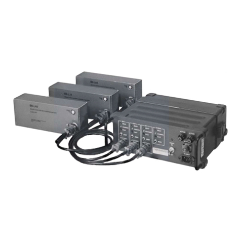
The PRC-PS is a combination power supply and dual battery charger designed
to power the PRC1099A transceiver, charge the BB-LA6 lead-calcium battery
inside the transceiver and charge an additional BB-LA6 simultaneously. The
PRC-PS can use a 50 or 60 Hz 110 VAC or 220 VAC (internally strapped) or a
20 Vdc to 30 Vdc power source.
The PRC-PS includes the following features:
• 12.5 Vdc power supply with two battery charging capacity
• 3-level charging circuitry
• AC or DC power source
• Front panel status LEDs for each charging station
• Front panel reset button
• Full short circuit protection

1: Introduction
1-2 PRC-PS-MS
1.2 Specifications
Note: All specifications subject to change without notice or obligation.
1.2.1
PRC-PS
Specifications
Characteristic Description
General
Input voltage 110/220 VAC or 20 to 30 Vdc (internally strapped)
Input current 1A (max.) at 110 VAC
0.75A (max.) at 220 VAC
9A (max.) at 20 Vdc to 30 Vdc
Reverse polarity
protection
Fully protected on DC input and battery outputs.
Electrical
Bulk charging rate 1.1A (C/5)
Bulk to overcharge
transition voltage
14.0 Vdc
Overcharge
terminate current
110 mA (C/50)
Float charge
voltage
13.3 Vdc
Float to bulk
transition voltage
12.0 Vdc
Temperature
coefficient on
voltage levels
-12 mV per °C
Current drain on
battery
5 µA max. (with power off)
Nominal charge
time
6 hrs (with 80% discharged battery)
Mechanical
Weight 4.6 kg (10 lbs.)
Size (HWD) 10 cm x 24 cm x 28 cm (4.0 in. x 9.5 in. x 11.0 in.)
Panel indicators POWER ON and FAULT CHARGING, READY for
each charger circuit.
Operating controls POWER on/off switch, RESET button for each
charger circuit, GAIN control with SPKR OFF.

1: Introduction
PRC-PS-MS 1-3
1.2.2
BB-LA6 Battery
Specifications
1.2.3
CY-2562
Battery Box
Specifications
Environmental
Temperature
Operating 0° C to +60°C (ambient)
Characteristic Description
Characteristic Description
Electrical
Nominal capacity 6 Ah
Nominal voltage 12 Vdc
Max. instantaneous
output current
30A at 20°C
Max. continuous
output current
7A at 20°C
Internal resistance 0.02 ohms max. (fully charged)
Percent of original
capacity versus
storage time
90% after 3 months
80% after 6 months
60% after 12 months
Mechanical
Weight 2.5 kg (5.5 lbs.)
Size (HWD) 9.4 cm x 24.2 cm x 5.8 cm (3.7 in. x 9.5 in. x 2.3 in.)
Characteristic Description
Mechanical
Weight 0.23 kg (0.5 lbs.)
Size 7.5 cm x 10 cm x 28 cm (3.0 in. x 4.0 in. x 11.0 in.)


PRC-PS-MS 2-1
CHAPTER 2
INSTALLATION
2.1 Unpacking
The PRC-PS is shipped in a heavy-duty corrugated cardboard carton. Do not
discard the cartons and packing materials in case the equipment needs to be
reshipped.
Inspect the PRC-PS for possible damage during shipment. Check all
accessories against the packing list. The packing list should include the
following items:
• PRC-PS Power supply and battery charger
• AC Power cord
• DC Power cord
• C991608 power cable
• CY-2562 Battery box
2.2 Power Configuration
2.2.1
AC Input
Power
The PRC-PS can be configured for 110 VAC or 220 VAC by opening the case
and changing the connections on the power transformer. A label on the case
indicates to what voltage level the transformer is set, however it is prudent to
visually inspect the power transformer to verify what input voltage it is
configured to accept. Refer to the Power Transformer Connections figure on
page 2-3.
CAUTION: Always remember to remove the AC power cable before
opening the PRC-PS case. If the charger is energized, the techni-
cian is exposed to dangerous voltages that can cause personal
injury or death from electrical shock.
To access the power transformer:
1. Make sure the PRC-PS is turned off and disconnected from any power
source (see CAUTION above).

2: Installation
2-2 PRC-PS-MS
2. Place the PRC-PS so the front panel is faced away from you. Locate and
remove the four captive screws that hold the front panel to the case.
3. Position the PRC-PS so the bottom side is facing you. Remove the four
screws that hold the inside chassis to the case (refer to the Captive and
Chassis Screws figure above).
4. Slide the chassis out of the case (the connections on the power
transformer behind the regulator circuit board).
5. If the transformer is configured for 110 VAC and you need it to be
220 VAC, desolder terminals 3, 4, 5 and 6. Remove the jumper wires
between terminal 2 and terminal 3, and the jumper between terminal 5
and terminal 6. Refer to the Power Transformer Connections figure on
page 2-3.
6. Install one of the jumpers between terminals 4 and 5. Resolder terminals
3, 4, 5, 6.
7. Reverse steps 2 through 4 to reassemble the PRC-PS.
Figure 2-1. Captive and Chassis Screws
BOTTOM
VIEW
FRONT PANEL
CASE

2: Installation
PRC-PS-MS 2-3
The PRC-PS is shipped with a molded AC power cable with a 3-wire plug and
jack. It may be necessary to modify the plug to fit non-standard US AC
receptacles. The following table provides the color codes for the AC power
cable.
2.2.2
DC Input Power The PRC-PS also ships with a 2-wire DC input (14 AWG) cable. One end of
the cable does not have a connector so that the appropriate connector can be
added to connect to a DC power source. The power source must provide
20 Vdc to 30 Vdc and be capable of supplying 9A. A 24V vehicle battery is a
typical DC power source.
The front panel DC INPUT connector is wired according to the figure below.
CAUTION: Do not operate the PRC-PS when connected to both an
AC and DC power source.
Figure 2-2. Power Transformer Connections
110
3
VAC
A
C
F
US
E
:
A
220
1.
5
VAC
A
C
F
US
E
:
A
1
2
3
4
5
6
7
8
SWITCH AC
PLUG
123456
SWITCH AC
PLUG
123456
Wire Type US Standard Color Code International Color Code
Phase Black Brown
Neutral White Blue
Ground Green Green/yellow stripe
Figure 2-3. DC Power Connection
AB
(+) 28 V
DC
(–)
GROUND
B
=
A
=
FRONT
PANEL
JACK DC
INPUT
CABLE
JACK
C
DC
POWER
CABLE
99160
9
A
AB
B

2: Installation
2-4 PRC-PS-MS
The PRC-PS does not require any alignment or adjustment for normal
operation.
2.2.3
DC Output
Power
The PRC-PS is designed to provide 12 Vdc to the PRC1099A transceiver to
power the radio and charge a BB-LA6 attached to the radio through the front
panel J1 connector. It can also charge an additional BB-LA6 lead-calcium
through the rear power connector J4.

PRC-PS-MS 3-1
CHAPTER 3
OPERATION
The PRC-PS front panel provides the following interfaces and controls.
Figure 3-1. PRC-PS Front Panel
SET BATT
CHARGING
READY
FAULT
RESET
INTERNAL
CHARGING
READY
FAULT
RESET
POWER
ON
OFF
DC FUSE
A
C FUSE DC INPUT AC INPUT
AUDIO GAIN
SPKR
OFF
SET POWER
Interface or Control Description
SET BATT Charging
Station
Provides 12.5 Vdc to power the PRC1099A
and charge the BB-LA6 installed in the
PRC1099A. The SET POWER connector (J1)
interfaces with the PRC1099A through the
C991608 cable.
INTERNAL Charging
Station
Charges a BB-LA6 attached to the back of the
PRC-PS.
Speaker Provides audio for the PRC1099A in receive
mode.
AC FUSE (F1) 1.5A 250 VAC fuse.
3A 115 VAC fuse
DC FUSE (F2) 10A 250 Vdc fuse.
AC INPUT Voltage
Connector (J3)
Accepts the 3-conductor AC cable provided
with the power supply.
DC INPUT Voltage
Connector (J2)
Accepts the 2-conductor C991609 DC power
cable also provided with the power supply.

3: Operation
3-2 PRC-PS-MS
CAUTION: Use the PRC-PS to charge BB-LA6 lead-calcium
batteries only. Attempting to recharge lithium, magnesium or
other battery types may result in explosion or release of toxic
material.
To set up the PRC-PS for powering the PRC1099A and charging BB-LA6
batteries:
1. Make sure the power transformer is configured correctly for the intended
power source. Refer to the AC Input Power section on page 2-1.
2. Connect the AC power cable to the front panel AC INPUT connector and
an AC (110 VAC or 220 VAC) power source, or connect the DC power
cable C991609 to the front panel DC INPUT connector and a DC (20 Vdc
to 30 Vdc) power source.
3. Connect the C991608 cable from the PRC-PS front panel SET POWER
connector to the PRC1099A accessory (ACC) connector.
4. Install an additional BB-LA6 battery to the rear of the PRC-PS.
5. Turn the front panel POWER switch to ON.
6. Push the front panel RESET button to start charging on one or both
charging stations.
7. Observe the front panel status LEDs for the charging stations in use. The
yellow CHARGING LED should be lit. For other LED indications, refer
to the Status LED Indications table below.
Interface or Control Description
POWER Switch (S1) 2-position on/off toggle switch that controls
both the AC and DC input lines.
AUDIO GAIN Control Adjusts the volume to the speaker.
Table 3-1. Status LED Indications
LED Meaning Required Action
FAULT Battery fuse is blown or
battery voltage is below
5 Vdc.
Note: It is normal for the
FAULT LED to go on if you
press RESET when a
battery is not installed.
Check battery fuse. If the
battery fuse is okay, the
battery is faulty. Discard
the battery.

3: Operation
PRC-PS-MS 3-3
CHARGING Battery is charging
normally.
None.
READY Battery is fully charged. Remove battery.
The battery may be left
connected to the charger.
Table 3-1. Status LED Indications (continued)
LED Meaning Required Action
Figure 3-2. Charging Configuration
PRC-PS BB-LA6
to
115/230 Vac
source
to
24 Vdc
source
C991609
C991608
J4
J1
J2J3
PRC1099A
BB-LA6

This manual suits for next models
1
Table of contents
Other Datron Batteries Charger manuals
