Donaldson TDS User manual

N° : 262-3054-UK Rev. : 08 Date : 09/04
INSTALLATION AND
OPERATION MANUAL
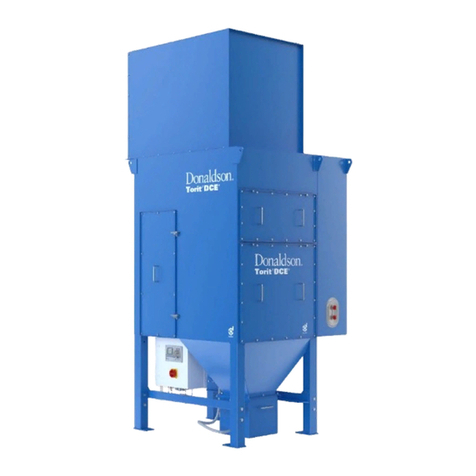
FOR TORIT DCE DUST COLLECTORS TYPE TDS
GPlease read this manual prior to installation and/or setting-up.

-2-
TABLE OF CONTENTS
1. SAFETY RECOMMENDATIONS.....................................................................................................3
2. INTRODUCTION..............................................................................................................................4
2.1 Product information ...................................................................................................................4
2.2 Working principle.......................................................................................................................5
3. DELIVERY AND INSPECTION........................................................................................................5
4. ERECTION OF THE EQUIPMENT..................................................................................................5
4.1 Location.....................................................................................................................................6
4.2 Required tools and equipment...................................................................................................6
5. Installation........................................................................................................................................6
5.1 Unloading and transporting to location......................................................................................6
5.2 Fan unit......................................................................................................................................7
5.3 Inlet duct....................................................................................................................................7
5.4 Platform .....................................................................................................................................7
5.5 Magnehelic gauge .....................................................................................................................8
5.6 Dust discharge systems ............................................................................................................8
5.7 Installation of elements..............................................................................................................8
6. INSTALLATION -ELECTRICAL SYSTEM......................................................................................9
6.1 General description of the electrical component parts..............................................................9
6.2 Control boxes with printed circuit boards ..................................................................................9
6.3 Solenoid valves connection (= pre-wiring).................................................................................9
6.4 Downtime pulsing......................................................................................................................9
7. INSTALLATION -PNEUMATIC SYSTEM.......................................................................................9
8. START UP .....................................................................................................................................10
9. SETTING THE VARIOUS FUNCTIONS........................................................................................10
10. OPERATION SCHEDULE ..........................................................................................................11
11. SERVICE.....................................................................................................................................11
11.1 Element replacement .................................................................................................................11
11.2 Dust Removal.............................................................................................................................12
11.3 Diaphragm valve ........................................................................................................................12
12. TROUBLE SHOOTING GUIDE...................................................................................................14
13. spare parts ..................................................................................................................................17
14. CONTACT ADDRESSES............................................................................................................18
15. CE DECLARATION.....................................................................................................................19
LIST OF FIGURES
FIGURE 1: TYPICAL INSTALLATION VIEW (TDS8 MODEL ILLUSTRATED)...............................................................................................4
FIGURE 2: OPERATIONAL SCHEMATIC..............................................................................................................................................5
FIGURE 3: FRONT VIEW ..................................................................................................................................................................7
FIGURE 4 : CROSS SECTION OF FILTERELEMENT...............................................................................................................................8
FIGURE 5: DIAPHRAGM VALVE ......................................................................................................................................................13
FIGURE 6: PARTS DRAWING (TDS16 MODEL ILLUSTRATED)............................................................................................................16

-3-
1. SAFETY
RECOMMENDATIONS
This manual contains specific precautionary
statements relative to worker safety in
appropriate sections. To avoid dangerous
situations we give you the following advice:
èNOTE
Refers to special information on how to
use the dust collector most efficiently.
GIMPORTANT
Refers to special information directed
towards preventing damage.
CAUTION
Refers to special information designed
to prevent injury or extensive damage.
CAUTION
a) The dust collector has been built in
accordance with state-of-the-art
standards and recognised safety rules.
Nevertheless if not handled carefully, it
may put people at risk, or also cause
damages.
b) The dust collector must only be used in
technically perfect condition in
accordance with its designated use and
the instructions set out in the operation
manual. Any functional disorders,
especially those affecting the safety,
should therefore be rectified
immediately.
c) Make sure to give proper training to
operators before start-up. The dust
collector is designed exclusively for use
in accordance with the scope of
delivery, drawing(s) and the
specification sheet.
d) The dust collector is not designed for
applications with combustible materials
involving a potential dust explosion risk
(e.g. buffing lint, paper, wood dust,
aluminium and magnesium).
e) It is not allowed to put lit cigarettes or
any burning object into the hood or
ducting of any dust collection system;
f) Regular maintenance is important for a
good performance of your dust
collector.
A prudent user of Torit DCE equipment
should consult and comply with all
relevant Fire Codes and/or other
appropriate codes when determining
the location and operation of dust
collector equipment.
A hand-operated supply-disconnecting
device is necessary for each incoming
electrical supply in accordance with EN
60204-1.
g) To prevent accidents the access to the
fan wheel must be impossible during
operation. Refer to EN 294.
h) Disconnect all power before servicing.
All electrical work must be done by a
qualified electrician according to local
codes.
i) All exposed conductive parts of the
electrical equipment and the dust
collector shall be connected to the
protective bonding circuit (refer to EN
60204-1).
j) Shutoff and bleed-off compressed air
supply before doing any service work
k) The dust collector cannot be used in a
potentially explosive atmosphere
(according ATEX directive 94/9/EC),
unless stated otherwise on the
nameplate of the unit and scope of
delivery.

-4-
1. Clean air Inspection cover
2. Diaphragm valve
3. Compressed air manifold
4. Dirty air chamber door
5. Tube sheet
6. Hopper
7. Legs
8. Bracing
9. Dust outlet
10. Filter elements
11. Lifting lugs
12. Clean air plenum
13. Clean air outlet
Figure 1: Typical Installation View (TDS8 model illustrated)
2. INTRODUCTION
2.1 Product information
The Torit DCE TDS Dust Collector is
used for the collection of airborne dust
and particulate. Whether in answer to the
problem of air pollution, or as part of a
manufacturing process, the TDS provides
highly efficient, continuous, on line dust
collection.
The filter elements are automatically
cleaned by putting alternate elements
temporarily out of action while the others
remain in operation. Element sizes are Ø
324 x 660 mm.
The cleaning cycle is adapted in each
individual case to the type and volume of
dust to be dealt with.
Technical and field support are always
available from your local Torit DCE
representative and distributors.

-5-
2.2 Working principle
During normal operation, contaminated
air enters the TDS through the inlet into
the inlet plenum where the dust is
collected on the outside surface of the
filter elements. The clean filtered air flows
through the center of the filter elements
into the clean air plenum where it exits
through the clean air outlet (figure 2). The
filter elements are automatically cleaned
with the aid of an electronic circuit board
through which the solenoid valves are
activated, the diaphragm valves opens
and a certain volume of compressed air is
blown into the filter element through the
manifold.
The compressed air pulse -with the
induced air added to it -flows through the
filter element and filter medium in a
direction opposite to the normal airflow.
The result is that the dust caught on the
outside of the filter element, is blown of
the filter element and falls into the hopper.
The air pulse lasts about 80-100
milliseconds, after which the diaphragm
valve closes and the filter element is back
in operation.
Normal Operation (left) Cleaning of Filterelements (right)
1. Clean air outlet
2. Dirty air inlet
3. Hopper
4. Heavy dust
5. Filter element
6. Tube sheet
7. Diaphragm valve
8. Air pulse
9. Dust
10. Dust Outlet
Figure 2: Operational Schematic
3. DELIVERY AND
INSPECTION
TDS dust collectors are usually shipped in one
or more separate parts, mounted on wooden
pallets. The shipments should be checked on
delivery for possible damage. Compare the
parts received against the packing list. If there
is damage or parts missing, notify the delivery
company and your local Torit DCE
representative.
Parts shipped loose with the delivery
(depending on your order):
•Hopper and leg set
•Dust disposal system
•Transition pieces
•Fan set
•Fan box
•Silencer
•Platform
•Spare parts
•Anchor bolts
•Hardware/Sealant
èNOTE
The collector comes with a can of paint
with the colour the unit is painted in. Use
it to touch up scratches and dents on the
bodywork.
4. ERECTION OF THE
EQUIPMENT
CAUTION
You should ensure all persons carrying
out work on the supplied equipment
follow any relevant recognised
standards or codes and are competent
to do so. Areas requiring competent
person include:

-6-
•Lifting and erection
•Electrical installation, inspection and
maintenance
•Pneumatic installation, inspection and
maintenance
4.1 Location
It is recommended to mount the TDS dust
collector on a reinforced concrete
foundation. It is also possible to install the
dust collector on another structure.
For the calculation of the load on the
foundation or on the structure; the
following factors will have to be
considered: the weight of the dust
collector, if necessary including fan/motor
units, as well as the maximum weight of
the dust taking into account the hopper
capacity and eventually the snow and the
wind conditions to be expected locally.
(see scope of delivery, specification sheet
and outline).
There should not be any obstructions
near the place where the collector is to be
located, for pipes, wires or protruding
roofs could cause problems for the crane
which in most cases will be necessary to
put the collector on the right spot.
To save time it is recommended to
prepare the foundation before the
collector arrives and in that case it is
essential to locate the anchor bolts
correctly.
The dust collector should be located with
consideration for:
•emptying the dust disposal (item 11, fig. 1)
•shortest runs of inlet and outlet ductwork
•radius bends on elbows as big as possible
•easy access to electrical and compressed
air connections
•convenience of maintenance.
4.2 Required tools and equipment
•Crane/Fork lift
•Slings/ Clevis Pins and adequate lifting
equipment
•Standard tools (e.g. screwdrivers,
wrenches, etc.)
•Drill
•Pipe Sealant
5. INSTALLATION
5.1 Unloading and transporting to
location
èNOTE
Before unloading remove all packing and
strapping.
•A crane is recommended for the
unloading, transport and installation of the
dust collector. A crane will be needed to
put the hopper in position on the
foundation and after that, the top section of
the collector on top of the hopper.
CAUTION
Chains or slings with an adequate safe
working load must be used. Refer to the
collector nameplate for weight of
equipment supplied by Torit DCE. The
chains must be long enough to ensure
that the lifting angle between diagonal
chains is not greater than 90°. When
using a forklift the forks must be of a
suitable length and adjusted to ensure a
stable lift.
èNOTE
Depending on the order, the hopper and
leg set come already pre-mounted. Only
the collector will still need to be mounted
on the hopper. Follow steps 6 and 7 when
this is the case.
1. Stand the hopper(s) up with the disposal
end up (hopper outlet).
2. Use drift pins to align the holes in the
hopper gussets and legs, and attach the
legs with the M16 x 40 bolts, washers and
nuts. Do not tighten hardware at this
time!
3. Use drift pins to align the holes in the
crossbracings on the rear side of the leg
set.
4. Recheck the position of the legs and
crossbracings against Figure ‘Leg bolting
details and ‘Standard Leg Packs’ and the
drawing.
5. Flip over the now-assembled hopper/leg
pack assembly so that it is standing on its
legs (hopper outlet pointing down). This
step may require a crane.
6. Lift the assembled collector onto the
foundation. Fasten each footplate of the
leg anchor bolts with flat washers, lock
washers and nuts. Do not tighten
hardware at this time! (Depending on the
type of anchor bolts, anchor bolts can be
mounted afterwards).
CAUTION
-7-
The dust collector must be anchored
(refer to the replacement parts list for the
type of anchor) and the wind bracing
supplied with the legs must be fixed onto
the legs in both directions (see outline
unit).
5.2 Fan unit
If the fan is supplied by Torit DCE, it will
be mounted on top of the collector. Bigger
fans usually are placed on the floor next
to the dust collector.
The opening in the collector for the fan
should be located between the cross
stiffeners and it is recommended to make
use of vibration dampers and a flexible
connection system.
5.3 Inlet duct
The dimensions of the inlet ducts should
be such that the required volume of air
can be exhausted at such a speed that no
dust is deposited in the inlet ducting.
Piping should be kept as short as
possible with bends having a maximum
radius. All connections should be carefully
sealed by means of sealant, paste or
tape. Connect the inlet duct onto the inlet
flange of the inlet plenum.
èNOTE
A control valve should be installed in the
suction pipe to prevent overloading the
collector when starting the unit because
of the low initial pressure drop of the filter
elements.
5.4 Platform
The platform is shipped loose and has to
be mounted on the unit according following
mounting instructions:
CAUTION
•Platform fully galvanised.
•Max allowable point load (on surface
200x200 mm): 1500 N
•Max allowable load: 200 kg/m²
•Grate: 30x30 mm
•Self-closing door
•Step 1: Mount frame 1 on supports (item 2)
and on legs (item 3) (14 x M12x35) (figure
‘Front view’).
•Step 2: Mount walking grid (item 4) on the
frames with normal fastening (1 fastener -
item 7 -near each corner) (figure ‘Front
view’ + detail).
•Step 3: Mount ladder (item 5) on frame (8 x
M10x30) (figure ‘Front view’).
èNOTE
Ladder can be mounted on either 270°
or 90°-side.
•Step 4: Mount guardrails (item 6) on frame
(56 x M10x30) (figure ‘Top view’)
•Step 5: Anchor the platform and the ladder
to the foundation.
1. Frame service platform
2. Support
3. Leg
4. Walking grid
5. Ladder
6. Guardrails
7. Fastener
8. TDS
Figure 3: Exploded view

-8-
5.5 Magnehelic gauge
(if not factory installed)
The gauge should be mounted in a
suitable place and in accordance with the
instructions supplied with it. Special
attention should be paid to the correct
connection of the high and low pressure
sides, the bottom connection is the high
pressure side.
5.6 Dust discharge systems
Dust collectors can be fitted with various
dust discharge systems (see scope of
delivery for your dust discharge system).
The selection of a suitable discharge
system depends on:
•the volume of the dust handled
•the nature of the dust concerned
•storage possibilities and ultimate
destination of dust
All dust discharge systems are mounted
underneath the dust hopper. Hoppers
have standard discharge outlets.
There are marked differences in flange
dimensions between the different types of
rotary airlocks, screw conveyors, double
acting valves or other discharge systems
so that in most cases a transition piece
will have to be used to connect the
discharge system to the discharge outlet
on the hopper. Such transition pieces can
be supplied by us on request (see scope
of delivery).
Whatever the discharge outlet, it can
always be easily fitted to the dust
collector. A 5 mm soft rubber gasket
should be used between all connecting
flanges to prevent leakage. Electric
motors should be connected in
accordance with the wiring diagram and
the local rules and regulations. Special
attention should be paid to the correct
direction of rotation.
To ensure an effective evacuation of dust
deposit in the hopper (for difficult
dischargeable types of dust) a vibrator
can be mounted on the hopper (as an
option). The vibrator will be controlled by
an optional vibrator module, which can be
added into the controller. For installation
see separate manual: "Vibrator module".
5.7 Installation of elements
(if not factory installed)
Unscrew the square nut of the crank until
it touches the lock nut at the end of the
crank.
Apply a thin coating of grease or vaseline
film to the gasket and hang the element
on the bracket with the square nut
descended into the slot provided for this
purpose.
Next, turn the crank by hand until the
filter element is satisfactorily secured, do
not use any tools to achieve this.
The gasket will now be sufficiently
compressed to prevent any leakage. The
cartridges in type TDS6 to TDS8 are fitted
in rows of 2 and in the other types in rows
of 4. Two rows of elements can be
reached through each door.
1. Crank
2. Square nut M12
3. Lock nut M12
4. Gasket of filter element
5. Filter element
6. Hanger Bracket
7. Tube plate
8. Sealring
Figure 4: Cross section of filterelement

-9-
6. INSTALLATION -
ELECTRICAL SYSTEM
6.1 General description of the electrical
component parts
The electrical system for the TDS dust
collectors consists of various component
parts. These are:
•the control box incorporating the printed
circuit board
•the pilot valve box containing the solenoid
valves
The standard power supplies of the
control boxes are: 220V/240VAC -50/60
Hz, 110V/115VAC -50/60 Hz and
24VDC.
GIMPORTANT
All the instructions related to the control
box are mentioned in a separate Torit
DCE manual. (ref. 1A3119-8064 for IPC
Controller). Make sure you refer to it
6.2 Control boxes with printed circuit
boards
All TDS-units can be fitted with either a
STD IPC-Controller or an IPC-Controller
with differential pressure switch (part
number 1A31599361 and 1A31599362
respectively). The control box is factory
mounted on the dust collector, according
to our standards (except when specified
by order).
6.3 Solenoid valves connection (= pre-
wiring)
Solenoid valves are factory pre-wired.
6.4 Downtime pulsing
If the cleaning of the filter elements is
difficult due to the nature of dust, it is
possible to operate the
electronic/pneumatic cleaning device with
the fan set shut off. We recommend this if
the dust collector is put out of operation
for a longer period. On the standard
control boxes there is a downtime pulse
function device that can be set by means
of a slide connector.
Be sure that during the cleaning cycle
after fan shut down the power supply to
the control box is not disconnected. See
OIM for Control boxes.
èNOTE
This prevents uneconomical use of
compressed air.
7. INSTALLATION -
PNEUMATIC SYSTEM
Connect the compressed air supply line to
the dust collector manifold (connection
1"BSP inside thread). In principle it is
possible to connect the supply to one side
or the other of the manifold, a plug will
have to be used to close the connection
opening on the opposite side.
The various couplings in the compressed
air system should be sealed with material
like Teflon tape or the Loctite product
"Pipe Sealant".
To make sure the compressed air in the
manifold is both clean and dry it is
recommended to include a compressed
air filter in the supply system.
A pressure regulator complete with
manometer should be fitted to be able to
control the compressed air pressure.
èNOTE
Care should be taken that the
compressed air filter/regulator and the air
lines are amply dimensioned.
GIMPORTANT
•Filter must never be filled with oil! Arrows
on the apparatus indicate the direction of
flow. Please pay attention to this during
assembly.
•Be sure that all compressed air
components are adequately sized to meet
the maximum system requirements of 50
Nliters per pulse at max 7 bar supply
pressure (= design pressure).
•The piping should be installed to provide
a fall in the directions of the airflow to
assist in the drainage. A blow-down cock
should be provided at the lowest point of
the installation.
•It is a requirement that adequate
precaution is taken to avoid exceeding
this pressure. Relief, safety valve is
required if the connected supply can
exceed this pressure. A label is also
attached to each manifold indicating
manifold design details.
•Compressed air requirements 600-700
kPa (6-7 bar)
•Clean (max. particle size: 50 µm)
•Free of condensate
•Max. oil content: 3 mg/m³

-10 -
GIMPORTANT
Clean and purge the air feed pipe before
connecting it to the manifold to make sure
all impurities, which could possibly clog
the valves, are removed.
8. START UP
Before starting up the dust collection
system, the following points have to be
checked first:
Electrical system
•Check voltage of controller.
•Check voltage of fan (and if applicable the
discharge systems).
•Check number of outlets in control box
actuated.
•Check fuses (2x) in controller.
Pneumatic system
•Check compressed air pressure (6 -7 bar
at filter).
•Check if oil/water drain is working.
•Is the compressed air main valve open?
Starting
•Close the damper valve 45 degrees or
halfway.
•Start rotary airlock or other discharge
system if applicable. Check direction of
rotation, if incorrect: stop, switch off main
voltage and exchange 2 feeds in cable
box of motor. Repeat start-up procedure.
•Start control box. Check that all solenoid
valves are operated.
•Start fan. Check direction of rotation. If
incorrect: stop, switch off main voltage
and exchange 2 feeds in cable box of
motor. Repeat start-up procedure.
•Check ∆P. It should read 0 -200 mm WG.
If less than 0, exchange tubes.
The dust collector is now operational!!
9. SETTING THE VARIOUS
FUNCTIONS
Adjust the control valve in the suction
pipe so that the required volume of air
passes the dust collector. Check if the
suction at all suction points of the system
is satisfactory.
èNOTE
Air volume can be measured with the aid
of a Pitot tube and U-tube pressure
gauge.
•On leaving the factory the circuit board is
set at a 10 second interval between the
cleaning of each filter element section.
If ∆p exceeds its expected value it can
usually be reduced by shortening the
interval period.
On completion of the running-in time the
difference in pressure across the filter
elements normally comes to 50 -100 mm
WG.
èNOTE
Do not raise the cleaning pulse time
above 80-100 ms. Longer pulses do not
improve cleaning results, but only waste
compressed air.
•The compressed air consumption can be
decreased by lengthening the interval
periods between the cleaning pulses (2 -
30 s).
If a differential pressure gauge/switch is
fitted it should be set at the desired ∆P;
as soon as this present level is reached
the cleaning system will automatically be
put in operation

-11 -
10. OPERATION SCHEDULE
To ensure a good performance of your dust collector follow the checkpoints mentioned below
according the timetable.
No. Checkpoint Type of control Recommended action Day
Weeks
24826
1. Control box Visual check delta P
See trouble shooting guide
in Controller manual X
2. Dust disposal
system Check contents of dustbin(s) If ¾ full, empty dustbin X
3. Fan set Excessive noise See trouble shooting guide
chapter 12 X
4Clean air chamber Emission : dust carry over in clean
air chamber See trouble shooting guide
chapter 12 X
5Controls settings
Check settings of both
potentiometers (pulse time 100
milliseconds, interval time 10
seconds) on the control box (see
separate manual)
Interval time normally to be
set at 10 seconds. Pulse
time 100 milliseconds.
X
6Filter/regulator Oil and/or water is in the reservoir Switch off and bleed
compressed air prior
servicing. Clean oil/water
separator. Check
compressor.
X
7Solenoid valves Noise of escaping air is produced See trouble shooting guide
x
8Diaphragm valves Noise of escaping air is produced See trouble shooting guide
X
9Doors Visual check gaskets Replace gaskets if
necessary X
10 Connecting ducts Check for leakage Repair if necessary X
11 Dust collector and
platform Check damage, strength and
corrosion Repair or replace if
necessary X
12 Filter element Preventive replacement of all filter
elements Unless otherwise specified in the scope of delivery
every 2 years.
11. SERVICE
CAUTION
•Disconnect electrical power before
servicing.
•Shut-off and bleed compressed air supply
before servicing any compressed air
components.
•No welding should be performed inside
unit without fire protection.
•Avoid contact or exposure to dust as
much as possible during servicing or
maintenance. Wear dust mask and
protective gloves.
11.1 Element replacement
Remove all filter elements, starting with
those nearest the door by turning crank
counterclockwise until crank is loose
enough to remove filter from hanger
bracket.
Disassemble crank from elements and
install in new elements as shown in
Figure “Cross Section of Filter Element”.
Install elements in cabinet as explained
under Installation of Elements.
èNOTE
All filter elements should be changed at
the same time.
CAUTION
Dust laden filters may be heavy and
difficult to handle when removed through
access door opening. Provide appropriate
means of access to replace elements in
safety in case no platform is installed.
GIMPORTANT
Do not drop the element on the floor or
any other hard surface. Damage to the
filter element will occur, resulting in
leakage
GIMPORTANT
The genuine Torit DCE filter element is
the only replacement filter that will provide
the high level of performance that you
expect from your investment in the Torit
DCE Dust collector.

-12 -
11.2 Dust Removal
GIMPORTANT
Do not let the dustbin overfill. It can cause
poor dust collector performance.
Turn off the dust collector and empty the
dustbin on a regular base (recommend to
empty the dustbin when 3/4 full).
If plastic bags are used, a pressure balance
pipe is recommended. If shipped loose it has
to be mounted according figure 7.
A hole is already predrilled in the back of the
hopper for the connection. If the system is
installed to remove the bin from the back (0°
position), a hole (dia 28.5 mm) has to be drilled
on the opposite side of the hopper. The
predrilled hole has to be closed.
CAUTION
Where the dust has self-heating
properties, it is important to remove any
deposits in the dust container to reduce
the risk of an explosion
11.3 Diaphragm valve
Valve disassembly and reassembly
CAUTION
Depressurise valve before making
repairs.
CAUTION
To avoid damage to the valve body,
DO NOT OVERTIGHTEN PIPE
CONNECTIONS. If Teflon tape, paste,
spray or similar lubricant is used, use
extra care due to reduced friction.
Depressurise valve. Proceed in the
following manner:
1. Remove bonnet bolts and valve bonnet.
2. Diaphragm assembly is now accessible for
cleaning or replacement. Replace
diaphragm assembly if worn or damaged.
3. Reassemble in reverse order of
disassembly paying careful attention to
exploded views provided for placement of
diaphragm assembly.
4. When replacing diaphragm assembly be
sure the marking "THIS SIDE OUT" on the
diaphragm assembly is facing the valve
bonnet and that the bleed hole in the
diaphragm assembly is in alignment with
cavity in valve body and bonnet. The
external contours of the diaphragm, body
and bonnet must all be in alignment.
5. Replace bonnet bolts and tighten in a criss-
cross manner. Torque bonnet bolts (4) 7 ±
Newton meters.
6. After maintenance operate the valve a few
times to be sure of proper opening and
closing.

-13 -
1. Retainer clip (*)
2. Coil
3. Washer spring
4. Bonnet bolts (4)
5. Sol base sub assembly
(torque to 20 Nm)
6. Silencer (*)
7. Spring (*)
8. Core assembly (*)
9. Valve bonnet
10.Marking "THIS SIDE OUT"
on diaphragm assembly to
face valve bonnet
11.Diaphragm valve (*)
12.Bleed hole in diaphragm
assembly must be in
alignment with cavity in
valve body and bonnet. The
external contours of the
diaphragm assembly, body
and bonnet must be in
alignment.
13.Valve body
(!) Place conical spring end on top
(*) Parts included in the diaphragm repair kit
Figure 5: Diaphragm Valve

-14 -
12. TROUBLE SHOOTING GUIDE
èNOTE
Please consult other manuals if necessary (e.g. controls, fans…)
CAUTION
Disconnect all power and compressed air supply before services.
TROUBLE POSSIBLE CAUSE REMEDY
A. Fan and motor does not
start 1. Wiring
a. Proper wire size not used for motor.
b. Not wired correctly.
c. Unit not wired for available voltage.
d. Input circuit down.
e. Electrical supply circuit down.
Rewire per local and national codes for proper
wire size.
Check and correct internal motor wiring for
proper connections for your voltage.
(reference Motor Manufacturer Wiring
Diagram on motor).
Correct wiring for proper input voltage.
Check input to motor circuits for voltage on all
leads.
Check the electrical supply circuit for proper
output voltage or fuse, circuit breaker fault.
Replace if necessary.
B. Fan and motor starts, but
does not keep running. 1. Starter kicks out.
a. Incorrect overload protection is installed.
b. Collector inspection door is off or not
closed tight.
c. Hopper discharge open to atmosphere.
d. Fan damper control not adjusted properly.
e. Electrical circuit fuses.
Check for proper motor overload protection.
Reset or replace if needed for proper value.
Tighten inspection door securely.
Install slide gate, drum cover arrangement, or
other accessories to hopper discharge. See
Dust Discharge System and Operating
Adjustments Section.
Check airflow in ducting for proper
requirements. Adjust the damper control until
the proper airflow is achieved and the fan
motor amperage draw is within manufacturer
motor ratings.
Check that the supply circuit has sufficient
power to run all equipment.
C. Excessive noise / vibration
of the fan unit
1. Fan wheel out of balance due to:
a. Dust deposit on the blades
b. Worn blades.
2. Worn bearings.
Clean the blades
Replace the fan wheel
Replace the bearings.
CAUTION
If this happens, it should be rectified at once.
D.Dust emission out of clean
air outlet 1. Filterelements installed improperly.
2. Filterelement damage, dents in the end
caps, gasket damage or holes in pleated
media.
3. Inspection door is loose.
Check that gaskets on the filterelement(s) are
facing into the cabinet first (see Filter-element
Installation Section located in this manual).
Check whether the seal rings at the bottom of
the filter elements are fitted.
Replace the filterelements. Use only genuine
Torit DCE filterelements (see Ordering
Information at spare parts list). See
Installation of Filter elements.
Tighten inspection door securely.

-15 -
TROUBLE POSSIBLE CAUSE REMEDY
E. Insufficient airflow 1. Fan rotation backwards.
2. Collector openings not tight or closed.
3. Fan exhaust area is restricted.
4. Filter elements plugged with particulate.
a. Filter elements need to be replaced.
b. Lack of compressed air.
c. Pulse cleaning not energized (pulse red
led does not light up).
d. Dust storage area is too full or plugged.
Check fan rotation. Refer to rotation sticker
on fan housing.
Check inspection door, that it is in place and
tightened securely. Also check hopper
discharge area that openings are closed off
and that the optional hopper attachments are
installed.
Check fan exhaust area for blockage.
Remove material or debris that is blocking the
fan exhaust area or adjust damper flow
control on fan exhaust area.
Remove and replace using only genuine Torit
DCE filter elements (see Filter Element
Installation and Replacement Parts List).
Check compressed air supply for 6 bar
minimum.
Refer to the trouble shooting guide from the
Controller Operating Manual.
Check wiring of solenoid valves (see
Electrical Connection Section and Field
Electrical Connection Schedule).
Clean out dust storage area.
5. Pulse valves are not functioning.
a. Pulse valves are leaking compressed air.
b. Pulse control printed circuit board has
failed.
c. Pulse control timer board is out of
adjustment.
Lock out all electrical power to the TDS and
bleed off the compressed air supply. Check
for debris, valve wear or diaphragm failure by
removing the diaphragm cover on the pulse
valves. Also check for solenoid leakage
and/or damage. If pulse valves or solenoid
valves are damaged replace part(s) (refer to
Replacement parts List).
Refer to the Operating Manual of the
Controller.
Refer to the Operating Manual of the
Controller.

-16 -
Figure 6: Parts Drawing (TDS16 model illustrated)

13. SPARE PARTS
Ref. nr. Description TDS 6 to 24 TDS 32 to 48
Venturi (plastic) N/A 262-2339
Lock nut M12 N/A 262-3004
Square nut M12 N/A 262-3003
Bracket N/A 262-3005
1Filter element see scope of delivery
2Seal ring 262-3002
3Crank 262-3001
Solenoid 24 VDC (spare coil) N/A AD1000123
Solenoid valve mounting hardware for coil N/A AD1000122
4Connection strip solenoid 6 valves 262-1307 N/A
Connection strip solenoid 12 valves 262-1308 N/A
4Enclosure with 4 solenoid valves (24 VDC) IP 65 N/A AD1000213
Enclosure with 6 solenoid valves (24 VDC) IP 65 N/A AD1000214
Enclosure with 8 solenoid valves (24 VDC) IP 65 N/A AD1000215
Tube elbow push-in fitting 6/8 N/A AD1000217
Tube flexible 6/8 black N/A AD1000218
5Diaphragm valve 262-0139 262-0007
Repair kit for diaphragm valve (diaphragm)
Repair kit for diaphragm valve (coil/connector kit)
262-0087
262-0138
262-0013
Bulkhead connector 3/4" (incl. compression nut + seal) N/A 262-0049
Manifold coupling 3/4" (incl. compression nut + seal) N/A 262-0050
Anchor bolt M16 for dust collector 262-2430
6Magnehelic kit 727-0229
CAUTION
In order to maintain the original collector specification and to ensure the same level of safety,
only genuine spare parts should be fitted.
èNOTE
When ordering parts, give model number and serial number of dust collector, description and
quantity of parts desired.

14. CONTACT ADDRESSES
Donaldson Europe B.V.B.A.
Torit-DCE Products
Interleuvenlaan 1
B -3001 Leuven (Heverlee)
Belgium
Tel.(gen) : + 32 (0)16 383 811
Tel.(sales) : +32 (0)16 383 970
Fax : +32 (0)16 383 938
Donaldson
Torit-DCE Products
Humberstone Lane
Thurmaston
Leicester LE4 8HP
United Kingdom
Tel. +44 (0) 116 269 6161
Fax : +44 (0)116 269 3028
Donaldson
Torit-DCEScandinavia
Adalsvej 50
DK-2970
Horsholm
Denmark
Tel. : +45 45 57 00 77
Fax : +45 45 57 00 44
E-mail: IFS-europe@mail.donaldson.com

15. CE DECLARATION
UK CE DECLARATION OF CONFORMITY
(Machinery directives 89/392/EEC and 91/368/EEC)
Manufacturer: Donaldson®Europe B.V.B.A.
Interleuvenlaan 1 -B-3001 Leuven, Belgium
Description of the machinery: Dust Collector
Brand: Donaldson Torit DCE
Type: TDS
Description: see attached scope of delivery
The undersigned, authorised by Donaldson Europe NV, certifies that the machine described above, provided that it is installed,
maintained and used in accordance with the instructions for use and the codes of practice, meets the essential safety and
health requirements of the "machinery" Directive and the following stipulations and standards:
−Machinery directives 89/392/EEC and 91/368/EEC
−Low voltage directive 73/23/EEC
−EN 60204-1 (ed. Oct. 92) safety of machinery. Electrical equipment of machines -General requirements
−Pressure equipment directive (97/23/EC)
−Electromagnetic compatibility Directive 89/336/EEC
−Equipment and protective systems intended for use in potentially explosive atmospheres 94/9/EC.
And the essential principles of the following standards
−EN292-1/-2 (ed. Sept 91) Safety of Machinery
−EN294 (ed. Jan.93) Safety of Machinery -Safety distances to prevent danger zones being reached by upper limbs.
IMPORTANT! Read the Operation and Instruction Manual before using this machine. If you
require additional copies contact your local Donaldson Torit DCE representative.
The machinery must not be put into service until the machinery into which it is to be incorporated has been declared in
conformity with the provisions of the above mentioned directives.
Signature: Date: 11 August 2004
Name: Jos Dottermans
Position: Director Torit DCE Europe
Table of contents
Other Donaldson Dust Collector manuals

Donaldson
Donaldson Torit DCE WSO Flex User manual

Donaldson
Donaldson DFPRE 4 Series User manual

Donaldson
Donaldson Torit DB-800 User manual

Donaldson
Donaldson Downflo Evolution DFE 2-8 User manual

Donaldson
Donaldson Torit RF Series User manual

Donaldson
Donaldson Torit PowerCore TG Series User manual

Donaldson
Donaldson PowerCore CPV Series User manual

Donaldson
Donaldson DFPRE 4L User manual

Donaldson
Donaldson DFOI4 User manual

Donaldson
Donaldson DCE HV500 Series User manual