daviteq MBRTU-TBD User manual

JUL-2021
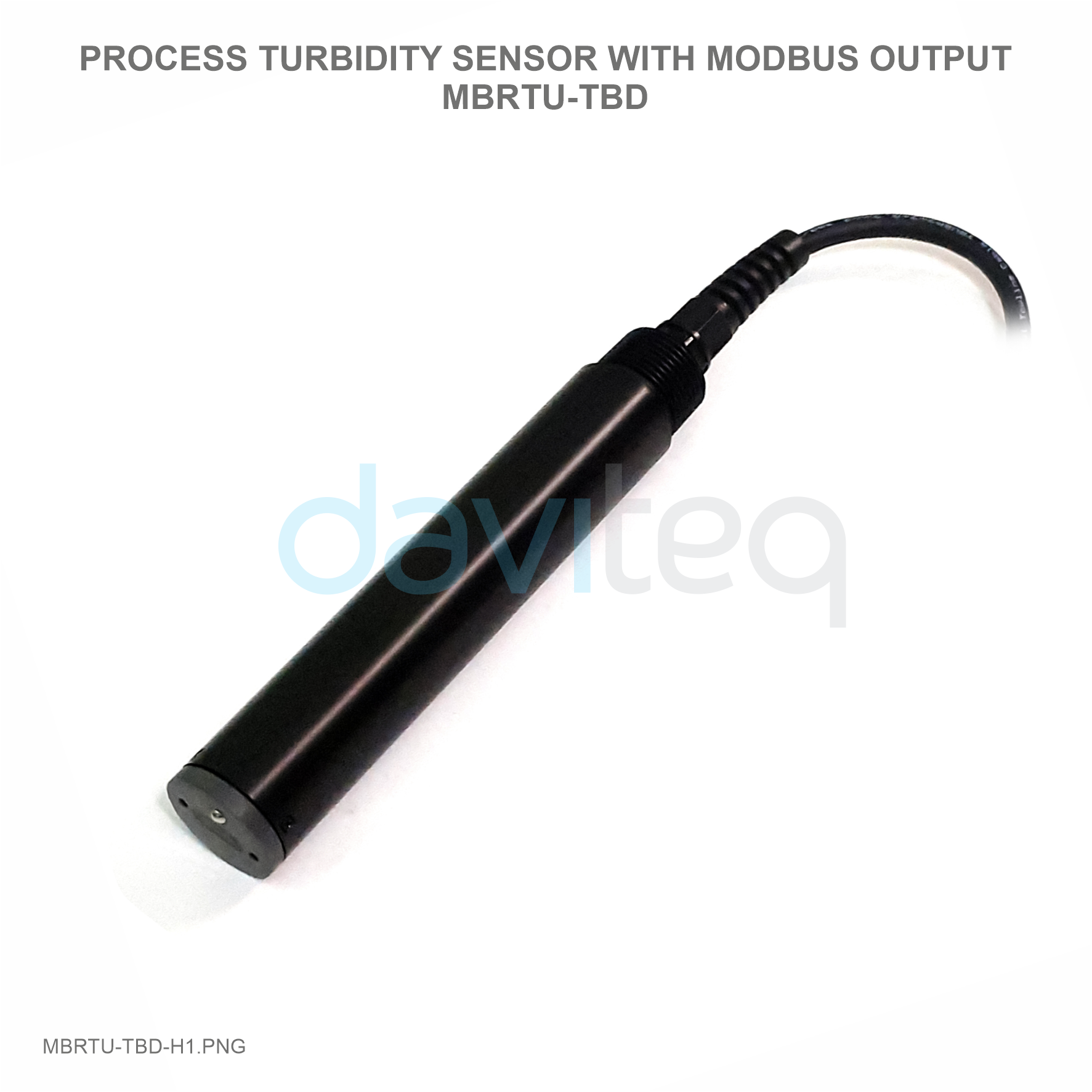
MBRTU-TBD is an advanced digital turbidity sensor for water quality monitoring, adopt the principle of scattered light,
the design method of using infrared LED light source and optical fiber conduction light path. The filter design is added
inside, which has strong anti-interference ability. Built in temperature sensor, automatic temperature compensation,
suitable for online long-term monitoring of the environment.
1. Digital sensor, direct output RS-485 digital signal, support Modbus / RTU
2. Principle of 90° Angle Scattering Light, the built-in temperature can be compensated automatically;
3. Optical fiber structure, strong resistance to external light interference
4. Infrared LED light source, add filter design, anti light interference, good stability
5. The surface shall be treated with anti-corrosion and passivation
6. Low power consumption and anti-interference design of internal circuit
Item
Specifications
Output
RS-485,MODBUS/RTU
Measuring method
90° scattered light method
USER GUIDE FOR TURBIDITY
SENSOR WITH MODBUS RTU
OUTPUT MBRTU-TBD
This document is applied for the following products
1. Introduction
2. Specification
Features
Technical Data

Range
0 ~ 1000NTU or 0 ~ 100NTU
Accuracy
±5% indication value or ±3NTU, choose the greater (0 ~ 1000NTU)
± 3% indication or ± 2 NTU, choose is greater (0-100 NTU)
±0.5℃
Resolution
0.1NTU, 0.1℃
Working environment
0 ~ 50℃, <0.6MPa
Calibration method
Two-point calibration
Response time
30s T90
Temperature Compensation
Automatic temperature compensation (Pt1000)
Power Supply
12-24VDC±10%, 10mA;
Size
Diameter 30mm; Length 166.5mm;
Protection level
IP68The water depth is 20 meters;
Service life
3 years or above
Cable length
5m
Sensor housing material
PVC
Please wiring as shown below:
Wire color
Description
Brown
Power (12-24VDC)
Black
GND
Blue
RS485A
White
RS485B
Bare line
Shielding Layer
Cable line 4 line AWG-24 or AWG-26 Shielding Wire.
Inductive electrode is basically maintenance free; It is recommended to clean up the sensor probe attachment
4. Wiring
5. Maintenance and Precautions
5.1 Maintenance

every 30 days; Avoid the use of hard objects to cause the damage of the light guide part of the measuring probe
during cleaning; Please wipe with a soft damp cloth.
It is recommended to clean the outer surface of the sensor with water flow. If there is still debris residue, please
wipe it with a wet soft cloth.
Installation measurement: avoid the installation measurement at the place where the water flow is turbulent, and
reduce the influence of water bubbles on the measurement. Keep the measuring probe 2cm away from the
bottom.
The probe of the sensor is fouling or attached with more organisms, so the cleaning force can be increased
appropriately. Slight scratch on the probe surface does not affect the normal use of the sensor. But pay attention
not to penetrate the shell of the probe.
Suggestion: the protective cover of our company should be selected to prevent the influence of microbial
attachment on the measurement results.
Problem
Possible Causes
Solution
The operation interface cannot be connected
or the measurement results are not displayed
Wrong cable connection
Check the wiring mode
Wrong sensor address
Check the address for errors
The measured value is too high, too low or the
value is continuously unstable
The sensor probe is attached by foreign objects
Clean the sensor probe surface
Other
Contact after sales
The default data format for Modbus communication of this sensor is:
MODBUS-RTU
Baud rate
9600 (default)
Device address
1 (default)
Data bits
8 bit
Parity check
None
Stop bit
1bit
Function code 03: Read (R) register value
Function code 06: Write (W) single register value
Register Address
(hex)
Name
R/W
Introductions
Number of registers
(byte)
Data type
5.2 Note
5.3 Other
6. Modbus RTU Protocol
6.1 Information frame format
6.2 Register Address:

0x0100
Temperature value
R
℃ value x10 (for
example: the
temperature of 25.6℃
is displayed as 256,
the default is 1
decimal.)
1 (2 bytes)
unsigned short
0x0101
Turbidity value
R
NTU value x10 (for
example, the turbidity
value of 15.1ntu is
displayed as 151,
with 1 decimal place
by default.)
1 (2 bytes)
unsigned short
0x1000
Temperature
calibration
R/W
Temperature
calibration: the
written data is the
actual temperature
value X10; Read out
data is temperature
calibration offset X10.
1 (2 bytes)
unsigned short
0x1001
Zero point calibration
R/W
Zero point calibration
in air. The data
written during
calibration is 0.
1 (2 bytes)
unsigned short
0x1003
Slope calibration
R/W
Calibrate in the
known standard
solution (50% - 100%
range), and write the
data as the actual
value of the standard
solution × 10.
1 (2 bytes)
unsigned short
0x2000
Sensor address
R/W
The default is 1, and
the data range is 1-
127.
1 (2 bytes)
unsigned short
0x2003
Baud rate setting
R/W
The default is 9600.
Write 0 is 4800; Write
1 is 9600; Write 2 is
19200.
1 (2 bytes)
unsigned short
0x2020
Restore factory
settings
W
The calibration value
is restored to the
default value and the
written data is 0. Note
that the sensor needs
to be calibrated again
after reset.
1 (2 bytes)
unsigned short
unsigned int (unsigned short)
The data consists of two integers.
XXXX XXXX
XXXX XXXX
Byte1
Byte0
Float, According to IEEE 754 (single precision);
The data consists of 1 sign bit, 8-bit exponent, and a 23 bit mantissa .
XXXX XXXX
XXXX XXXX
XXXX XXXX
XXXX XXXX
Byte3
Byte2
Byte1
Byte0
Sign
bit
Exp digit
F decimal
6.3 Data structure type
Integer
Float
6.4 Modbus RTU command:
6.4.1 Function code 03h: read register value

Host send:
1
2
3
4
5
6
7
8
ADR
03H
Start register
high byte
Start register
low byte
Register
number high
byte
Number of
registers low
byte
CRC low byte
CRC high byte
The first byte ADR: slave address code (= 001 ~ 254)
Byte 2 03h: read register value function code
Byte 3 and 4: start address of register to be read
To read the FCC instrument,
Bytes 5 and 6: number of registers to read
Bytes 7 and 8: CRC16 checksums from bytes 1 to 6
Slave return:
1
2
3
4 , 5
6 , 7
M-1 , M
M+1
M+2
ADR
03H
total bytes
Register data
1
Register data
2
……
Register data
M
CRC low byte
CRC high
byte
The first byte ADR: slave address code (= 001 ~ 254)
Byte 2 03h: return to read function code
The third byte: the total number of bytes from 4 to m (including 4 and m)
Bytes 4 to m: register data
Byte m + 1, M + 2: CRC16 check sum from byte 1 to M
When the slave receives an error, the slave returns the error:
1
2
3
4
5
ADR
83H
Information code
CRC low byte
CRC high byte
The first byte ADR: slave address code (= 001 ~ 254)
Byte 2 83h: error reading register value
Byte 3 information code: 01 - function code error
03 - data error
Bytes 4 and 5: CRC16 checksums from bytes 1 to 3
Host send
1
2
3
4
5
6
7
8
ADR
06
Register high
byte address
Register low
byte address
Data high byte
Data low byte
CRC code
Low byte
CRC code
High byte
When the slave receives correctly, the slave sends back:
1
2
3
4
5
6
7
8
ADR
06
Register high
byte address
Register low
byte address
Data high byte
Data low byte
CRC code
Low byte
CRC code
High byte
When the slave receives an error, the slave returns:
1
2
3
4
5
ADR
86H
Error code information
code
CRC code
Low byte
CRC code
High byte
6.4.2 Function code 06h: write single register value

The first byte ADR: slave address code (= 001 ~ 254)
The second byte 86h: write register value error function code
Byte 3 error code information code: 01 - function code error
03 - data error
Byte 4 and 5: CRC check sum from byte 1 to 3
a) Change slave address:
Address:0x2000 (42001)
Number of registers: 1
Function code: 0x06
Default sensor address: 01
Change the Modbus device address of the sensor, and change the device address from 01 to 06. The example is as
follows:
Send command: 01 06 20 00 00 06 02 08
Respond: 01 06 20 00 00 06 02 08; Note: the address is changed to 06 and stored after power failure.
b) Baud rate:
Address: 0x2003 (42004)
Number of registers: 1
Function code: 0x06
Default value: 1 (9600bps)
Supported values: 0-2 (4800-19200bps)
The baud rate can be changed by the upper computer setting, and it can work without restart after the change. The
baud rate saves the upper computer setting after power failure. Baud rate support 4800960019200. The baud rate of
integer value allocation is as follows:
Integer
Baud rate
0
4800 bps
1
9600 bps
2
19200 bps
Send command: 01 06 20 03 00 02 F3 CB
Respond: 01 06 20 03 00 02 F3 CB Note: the baud rate is changed to 19200bps and saved after power failure.
a) Measuring temperature command:
Address: 0x0100 (40101)
Number of registers: 1
Function code: 0x03
Read sample values: 19.2℃
Send command: 01 03 01 00 00 01 85 F6
Respond: 01 03 02 00 C0 B8 14
6.5 Command example
6.5.1 Default register
6.5.2 Function register

Returns hexadecimal unsigned integer data, temperature value = integer / 10, 1 bit decimal place is reserved.
b) Turbidity measurement instruction:
Address: 0x0101 (0x40102)
Number of registers: 1
Function code: 0x03
Read sample values: 9.1 NTU
Send command: 01 03 01 01 00 01 D4 36
Respond: 01 03 02 00 5B F9 BF
Register returns hexadecimal unsigned integer data, turbidity value = integer / 10, 1 decimal place reserved.
c) Continuous reading of temperature and turbidity instructions:
Address: 0x0100 (40101)
Number of registers: 2
Function code: 0x03
Read sample values: Temperature 19.2 ℃ and turbidity 9.1 NTU
Send command: 01 03 01 00 00 02 C5 F7
Respond: 01 03 04 00 C0 00 5B BB F4
Register returns hexadecimal unsigned integer data, temperature value = integer / 10, 1 decimal place reserved
Register returns hexadecimal unsigned integer data, turbidity value = integer / 10, 1 decimal place reserved.
d) Humidity measurement command:
Address: 0x0107 (40108)
Number of registers: 1
Function code: 0x03
Read sample values: relative humidity 40%
Send command: 01 03 01 07 00 01 34 37
Respond: 01 03 02 01 90 B9 B8
Register returns hexadecimal unsigned integer data, humidity value = integer / 10, 1 decimal place reserved.
a) Temperature calibration
Address: 0x1000 (41001)
Number of registers: 1
Function code: 0x06
Calibration example: calibration at 25.8 ° C
Send command: 01 06 10 00 01 02 0D 5B
Respond: 01 06 10 00 01 02 0D 5B
The sensor needs to be calibrated in a constant temperature environment after the temperature indication no longer
fluctuates.
b) Turbidity zero calibration
Address: 0x1001 (41002)
6.5.3 Calibration instruction

Number of registers: 1
Function code: 0x06
Calibration example: calibration in air
Send command: 01 06 10 01 00 00 DC CA
Respond: 01 06 10 01 00 00 DC CA
c) Turbidity slope calibration
Address: 0x1003 (41004)
Number of registers: 1
Function code: 0x06
Calibration example: calibration in 50NTU turbidity solution
Send command: 01 06 10 03 01 F4 7D 1D
Respond: 01 06 10 03 01 F4 7D 1D
7. Dimensions

Manufacturer
Daviteq Technologies Inc
No.11 Street 2G, Nam Hung Vuong Res., An Lac Ward, Binh Tan Dist., Ho Chi Minh City, Vietnam.
Tel: +84-28-6268.2523/4 (ext.122)
Email: info@daviteq.com | www.daviteq.com
Revision #31
Created Tue, Jul 20, 2021 3:06 AM by Tien Nguyen
Updated Fri, Jul 23, 2021 3:07 AM by Tien Nguyen
8. Contact
Table of contents
Other daviteq Measuring Instrument manuals

daviteq
daviteq WS433-ULC User manual

daviteq
daviteq WS433-CO2 User manual

daviteq
daviteq MBRTU-SAL User manual

daviteq
daviteq WS433-M12F-ATH User manual

daviteq
daviteq WS433-MA-31 User manual

daviteq
daviteq CAP10CNC User manual

daviteq
daviteq WSSFC-G4F-NH3 User manual

daviteq
daviteq Sigfox WSSFC-PPS User manual
Popular Measuring Instrument manuals by other brands


Bushnell
Bushnell Pro 1m 205107 instruction manual

Jeulin
Jeulin Initio 2 manual

Amphenol
Amphenol THE MODAL SHOP 831 quick start guide

Acrel
Acrel APM Series Installation and operation instruction

Halma
Halma Ocean Optics DH-mini UV-Vis-NIR Installation and operation manual

ATAGO
ATAGO PAL-89S instruction manual