daviteq WS433-M12F-ATH User manual

WS433-M12F-ATH-MN-EN-01
FEB-2020
SKU
WS433-M12F-ATH
HW Ver.
2.5
FW Ver.
5.04
Item Code
WS433-M12F
Wireless Sensor Transmitter 433Mhz, compatible with all DULP sensor modules, AA 1.5VDC
battery, IP67
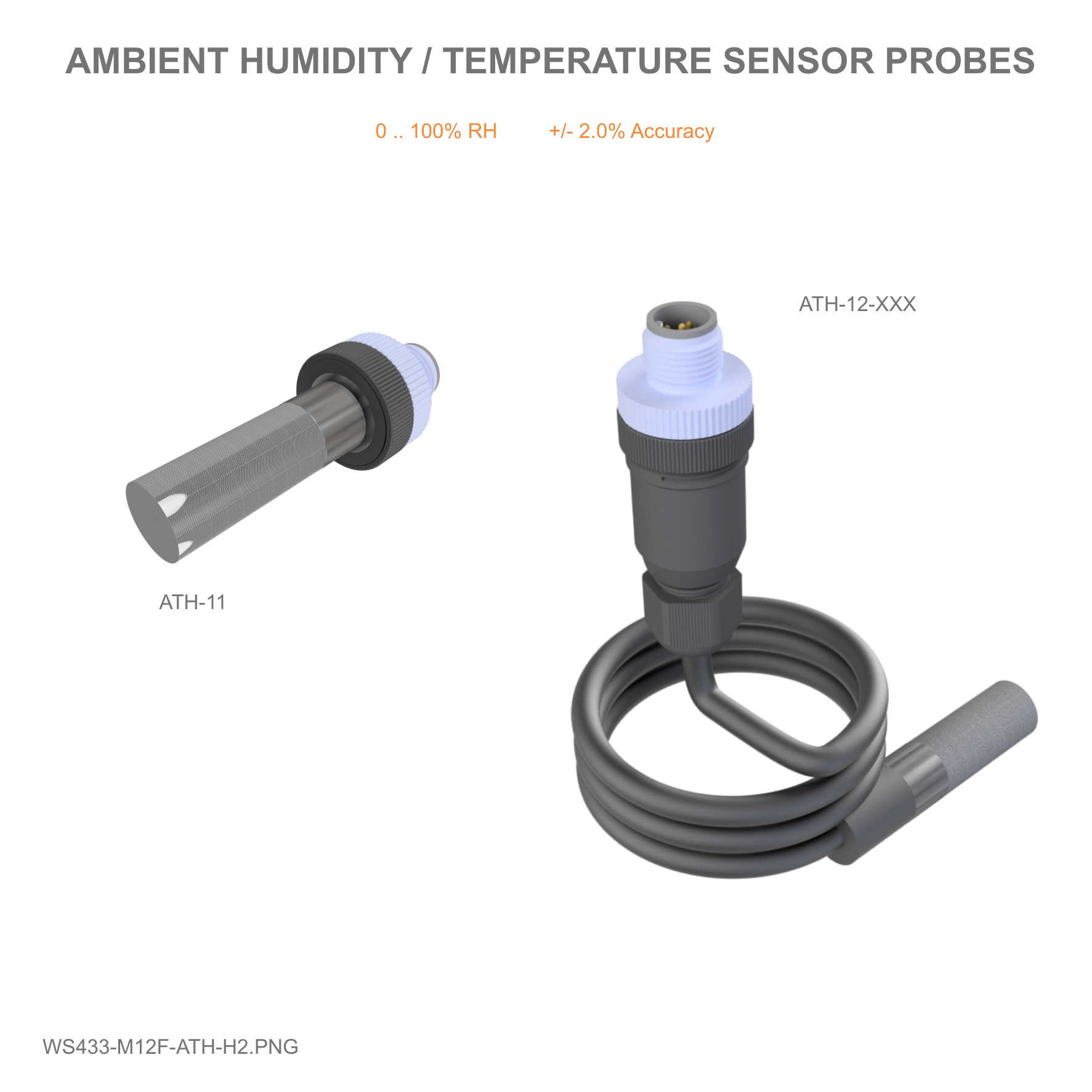
ATH-11
Compact ambient Humidity & Temperature Sensor DULP module, M12-male connector
ATH-12-300
300mm Cable type ambient Humidity & Temperature Sensor DULP module, M12-male connector
Notes
* Must order for both wireless transmitter and sensor module
HW Ver.
FW Ver.
Release Date
Functions Change
2.5
5.04
NOV-2019
Change RF data rate by
button
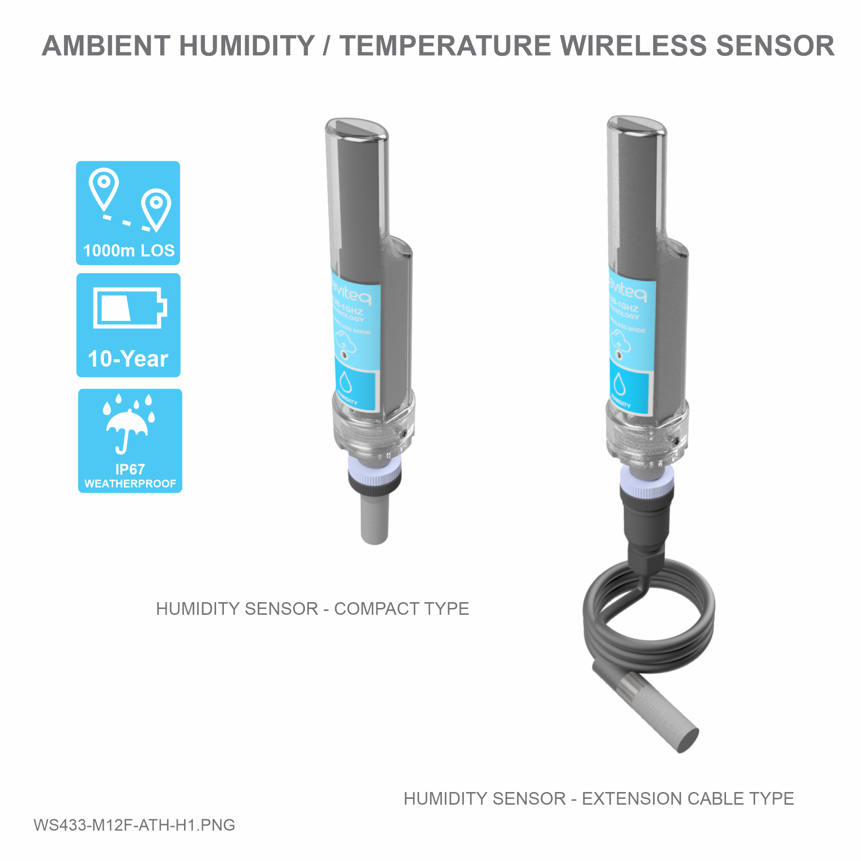
Wireless Ambient Humidity & Temperature Sensor is a combination of wireless sensor transmitter WS433-M12F and
sensor ATH, it utilises Digital capacitance humidity sensor to deliver high accuracy and stable measurement. The
wireless portion is Sub-GHz technology from Texas Instruments allows long range transmission at ultra-low power
consumption. It will connect 2-way wirelessly to the wireless co-ordinator WS433-CL to send data and receiving the
configuration. It can be configured the operation parameters like data sending interval, health check cycle...remotely
from Globiots platform or via ModbusRTU software (thru the WS433-CL). Its default data rate is 50 kbps, can be
switched to 625 bps to increase the communication range. It can last up to 10 years with a single AA battery. There are
a lot of applications as environment monitoring for office, warehouse, data center, hospital, agriculture...
USER GUIDE FOR WIRELESS
AMBIENT HUMIDITY &
TEMPERATURE SENSOR WS433-
M12F-ATH
This document is applied for the following products
1. Functions Change Log
2. Introduction

SENSOR SPECIFICATION :
Sensor
Digital type, factory calibrated, output both Humidity & Temperature
values
Humidity measuring range & accuracy
0 .. 100 %RH, +/- 2.0%
Humidity resolution
0.1%
Temperature measuring range & accuracy
-40 .. + 85 oC, +/- 0.2 oC
Temperature resolution
0.1 oC
Sensor Filter
20um Alloy sintered filter
Electrical connection
M12-male connector
WIRELESS TRANSMITTER SPECIFICATION :
Data speed
Up to 50kbps
Tranmission distance, LOS
1000m
Antenna
Internal Antenna
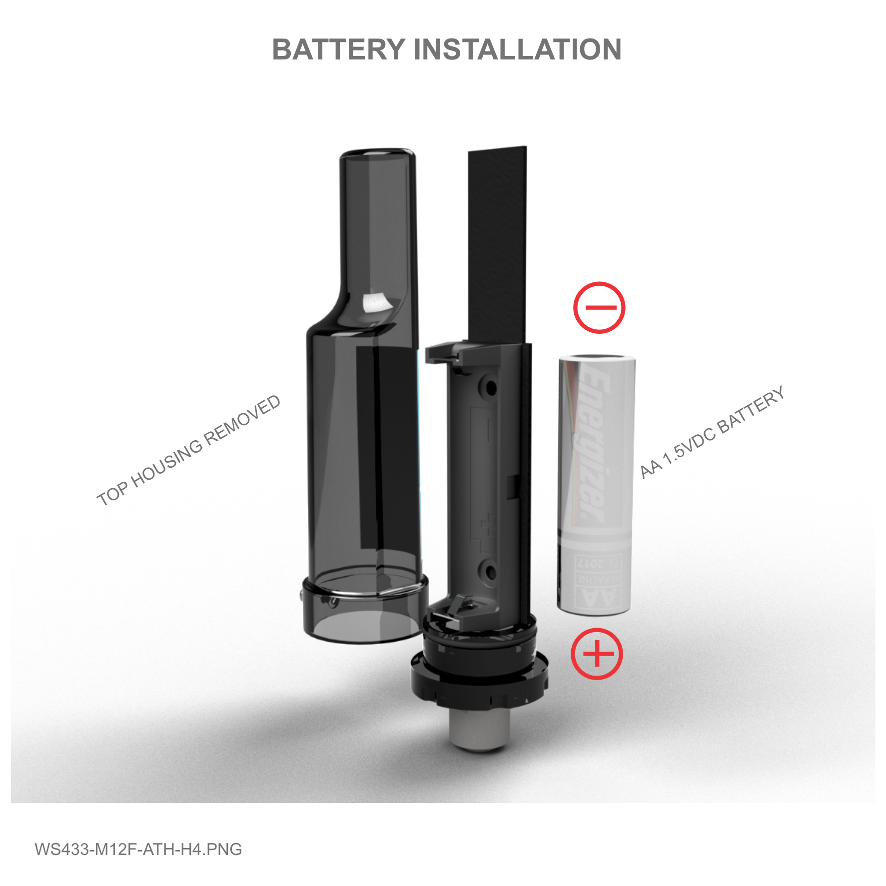
Battery
01 x AA 1.5-3.6VDC, up to 10-year operation, depends on configuration
Frequency Band
ISM 433Mhz, Sub-GHz technology from Texas Instrument, USA
International Compliance
ETSI EN 300 220, EN 303 204 (Europe) FCC CFR47 Part15 (US), ARIB
STD-T108 (Japan)
Vietnam Type Approval Certification
QCVN 73:2013/BTTTT, QCVN 96:2015/BTTTT (DAVITEQ B00122019)
3. Specification

Security Standard
AES-128
Operating temperature of PCB
-40oC..+60oC (with AA L91 Energizer)
Housing
Poly-carbonate, IP67
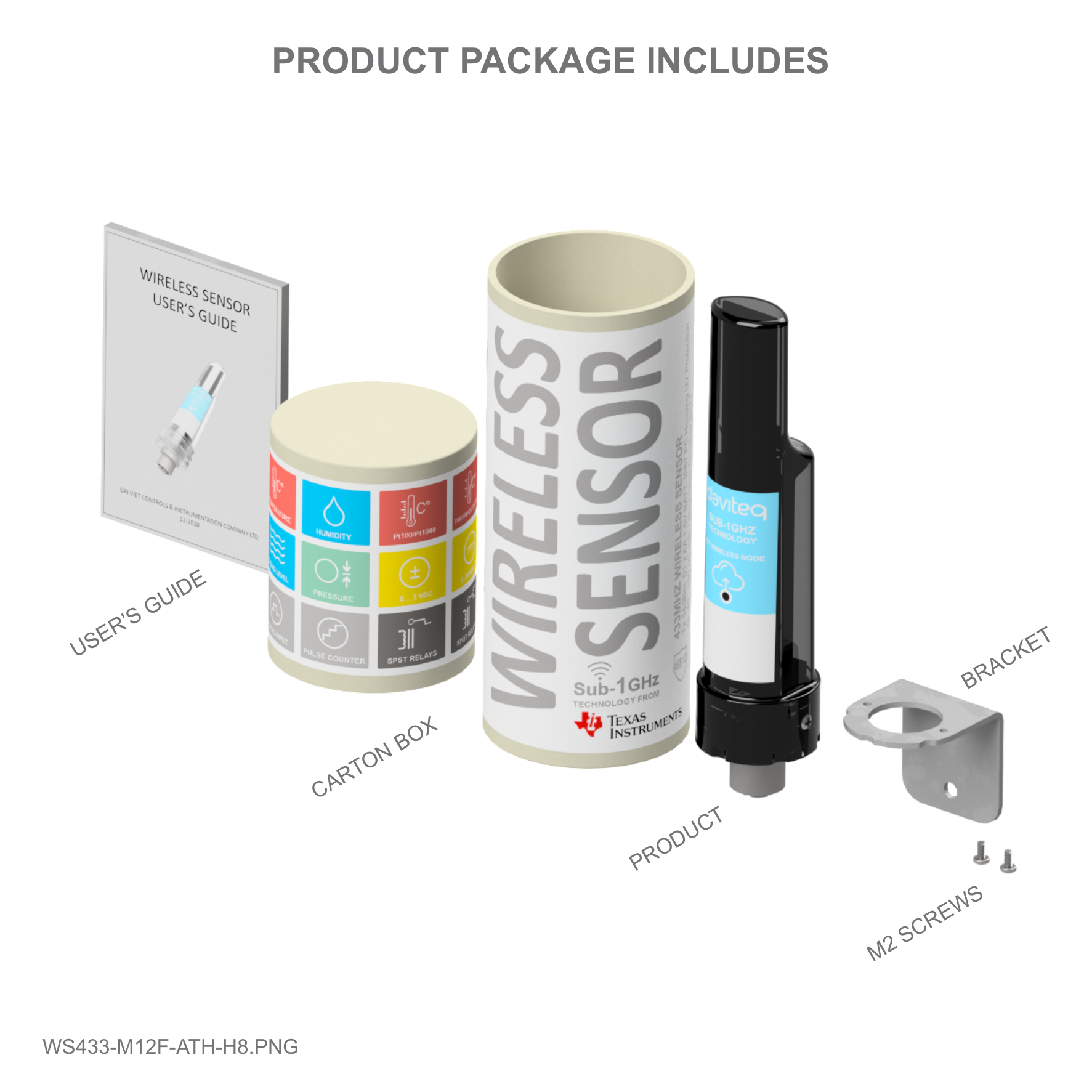
Installation method
L-type bracket SUS304 , by M4 screws or double-sided 3M tape
(included)
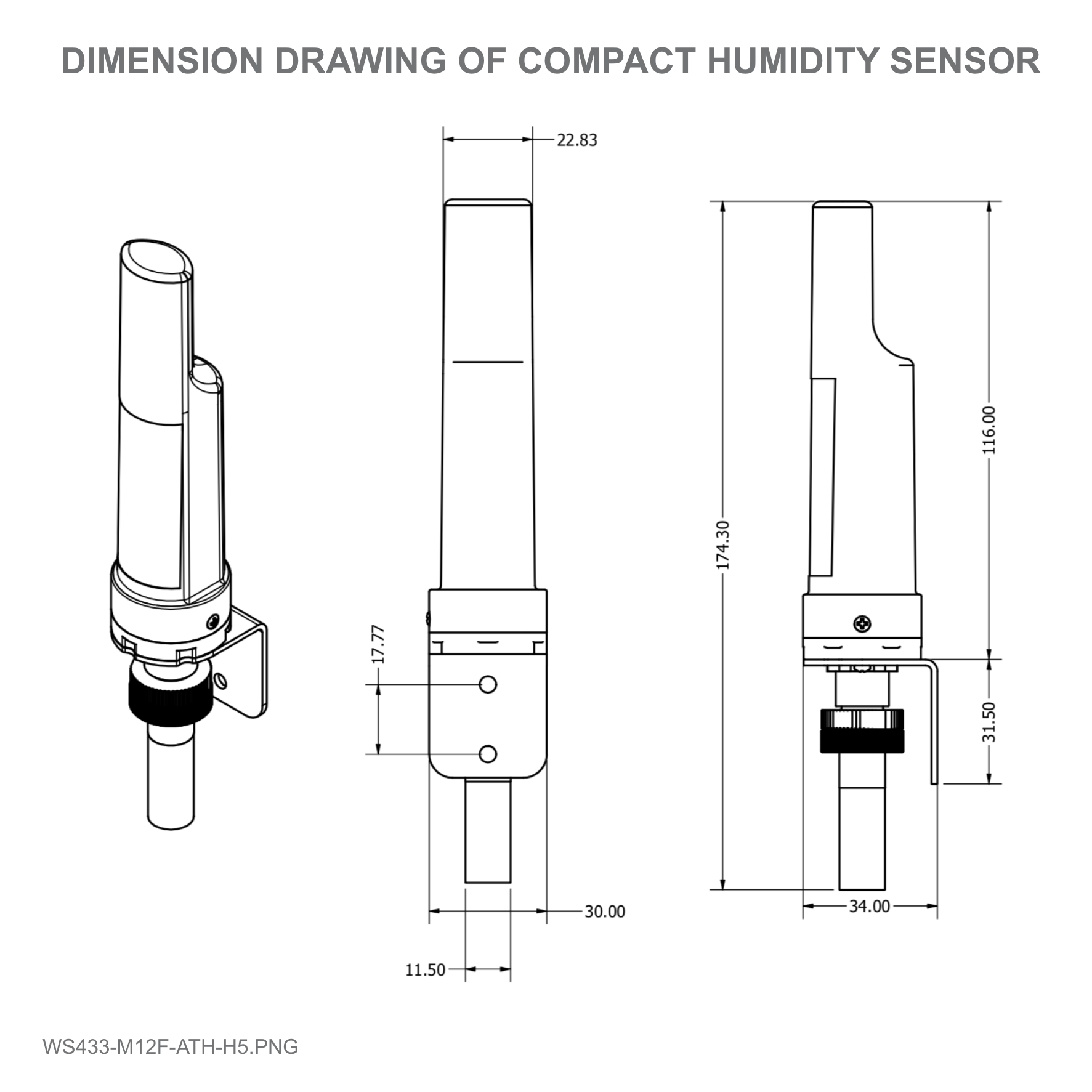
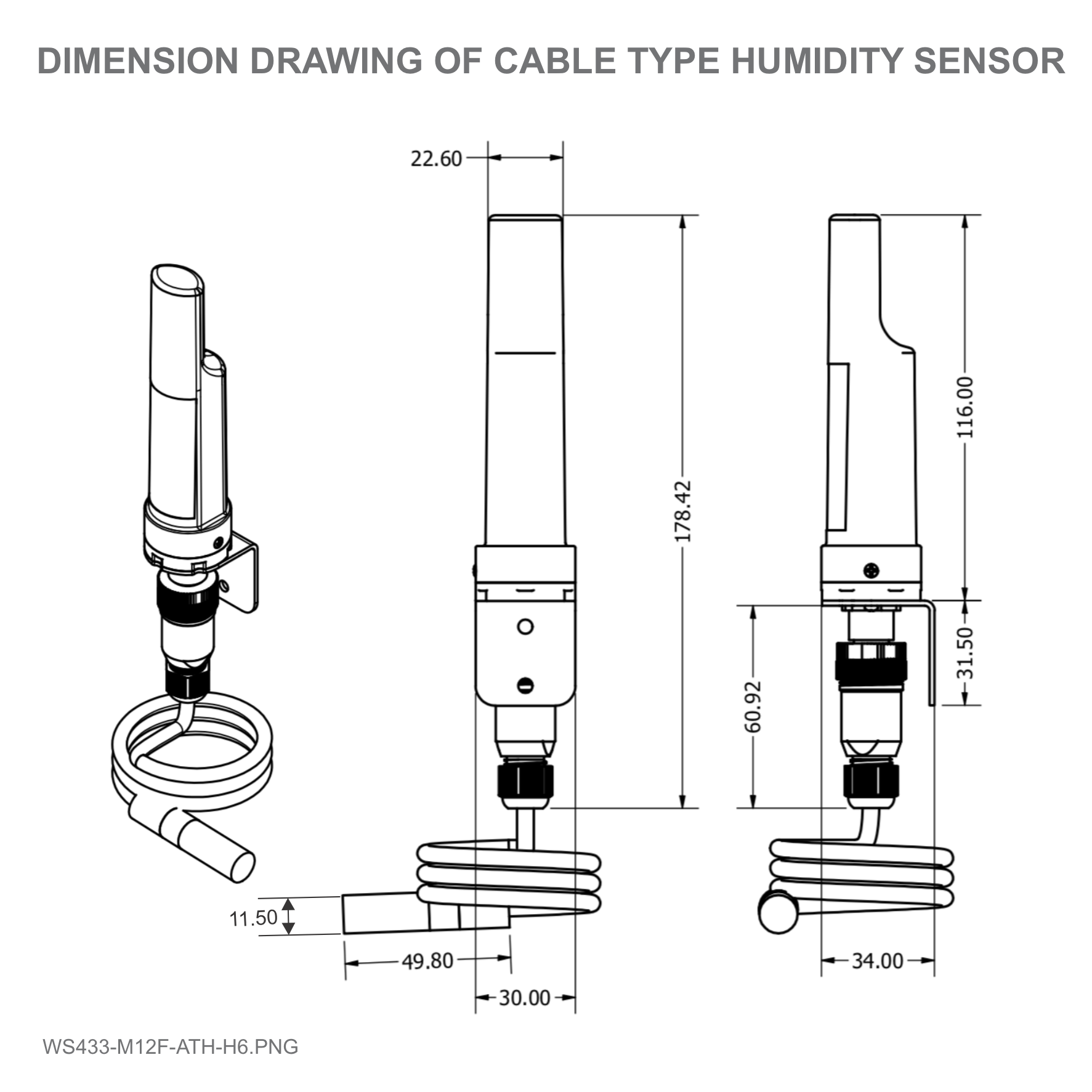
Product dimensions & weight
125x30x30mm, < 60g (without battery)
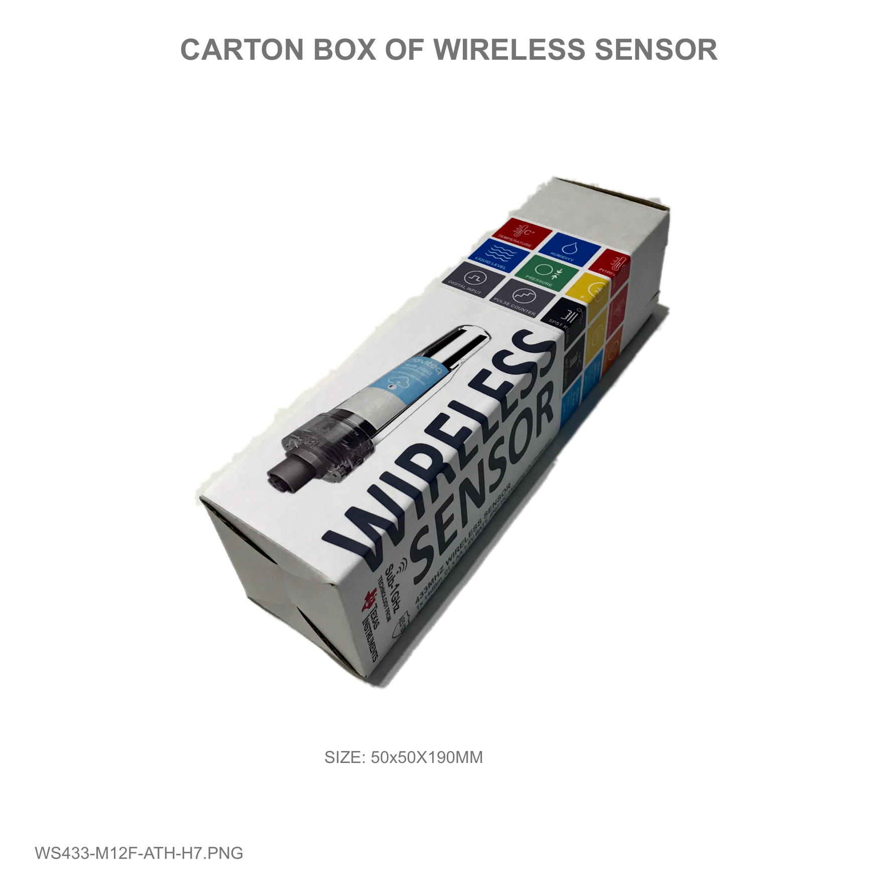
Box dimension & gross weight
190x50x50mm, < 100g
4. Product Pictures

Process of measurement
When the sensor sampling time interval is reached, for example 2 minutes, the node will wake up and switch ON the
power supply to supply the energy to external sensor to start the measurement. Depends on the type and
characteristic of external sensor, the sensor will take a certain time to finish the measurement.
For example, the measurement time is 200mS, after this time, the node will read the value of sensor using I2C, node
will switch OFF power supply to external sensor to save energy.
Once reading the sensor value, the raw data is X, it can be scaled to any engineering value by the following formula:
Y = aX + b
Where:
X: the raw value, reading from output of sensor before calibrated/validated;
Y: the calculated value, a desired output value of sensor, after calibrated/validated;
a: constant (default value is 1)
5. Operation principle

b: constant (default value is 0)
By default a= 1 and b=0 ==> Y=X
The Y value will be compared with Lo and Hi threshold.
Status bytes of sensor Node
Hi-Byte is error code
Error code
Description
0
No error
1
Just exchange the sensor module but node has not been reset ==>
please take out the battery for 20s then install it again to reset node to
recognize the new sensor module
2
Error, sensor port M12F shorted to GND
3
Error, sensor port M12F shorted to Vcc
4
Error, sensor port M12F shorted each other
Lo-Byte is sensor type
Error code
Description
0
No error
1
Just exchange the sensor module but node has not been reset ==>
please take out the battery for 20s then install it again to reset node to
recognize the new sensor module
2
Error, sensor port M12F shorted to GND
3
Error, sensor port M12F shorted to Vcc
4
Error, sensor port M12F shorted each other
Logic status of parameters
Hi-Byte is Logic status of parameter 1
If parameter 1's value > high threshold 1 => Hi-Byte of Logic status = 1
If parameter 1's value < low threshold 1 => Hi-Byte of Logic status = 0
If parameter 1 is digital => Hi-Byte of Logic status = parameter 1's value
Timer up 1 = (Total time when Hi-Byte of Logic status = 1)
Timer down 1 = (Total time when Hi-Byte of Logic status = 0)
RisingEdge counter 1 = (Counter value when Hi-Byte of Logic status changes from 0 to 1)
FallingEdge counter 1 = (Counter value when Hi-Byte of Logic status changes from 1 to 0)
Lo-Byte is Logic status of parameter 2
If parameter 2's value > high threshold 2 => Lo-Byte of Logic status = 1
If parameter 2's value < low threshold 2 => Lo-Byte of Logic status = 0
If parameter 2 is digital => Lo-Byte of Logic status = parameter 2's value
Timer up 2 = (Total time when Lo-Byte of Logic status = 1)
Timer down 2 = (Total time when Lo-Byte of Logic status = 0)
RisingEdge counter 2 = (Counter value when Lo-Byte of Logic status changes from 0 to 1)
FallingEdge counter 2 = (Counter value when Lo-Byte of Logic status changes from 1 to 0)
Ambient Temperature Sensor Module (ATH)
Feature of measuring humidity in environment:
Humidity measuring range & accuracy: 0 .. 100 %RH, +/- 2.0%
Resolution ±0.1%
Long-term Drift ±0.25%RH/year
Feature measuring ambient temperature:
Temperature Range -40oC to +125oC
Accuracy ±0.4oC
Resolution ±0.1oC
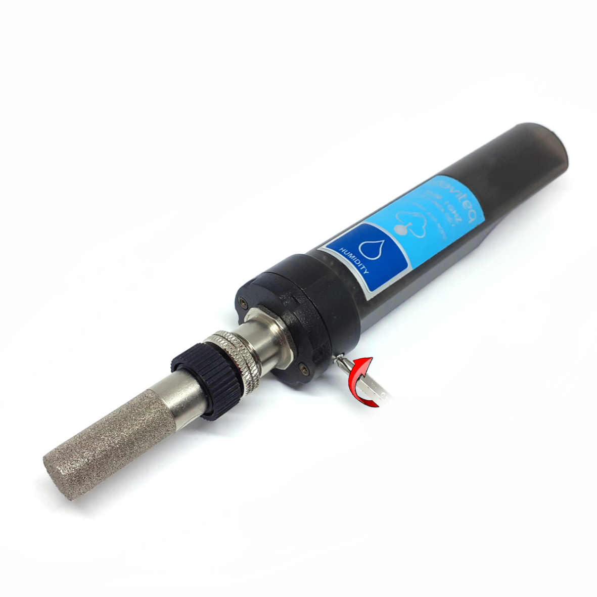
6. Configuration

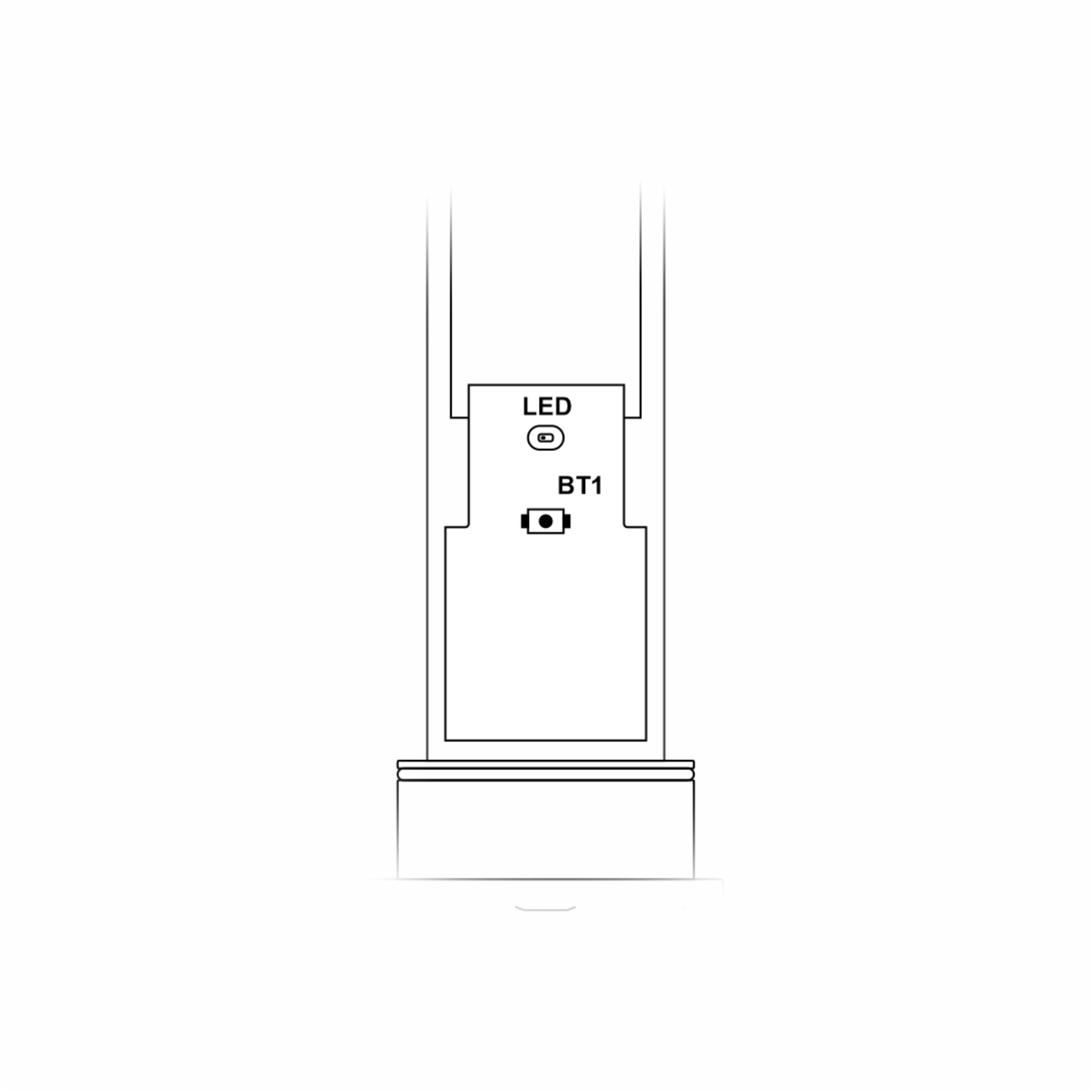
Step 1: Using Philips screw driver to unscrew M2 screw at the side of housing and carefully pull out the top
plastic housing in the vertical direction.
Step 2: Press the button until you see LED flashes 3 times to reset
Take off the sensor cover like Step 1 and press the button until you see LED flashes 2 times for 625 kps option
You can configure the wireless sensor with the co-ordinator by following the steps in the link below:
http://www.daviteq.com/en/manuals/books/long-range-wireless-co-ordinator-ws433-cl/page/user-guide-
for-long-range-wireless-co-ordinator-ws433-cl
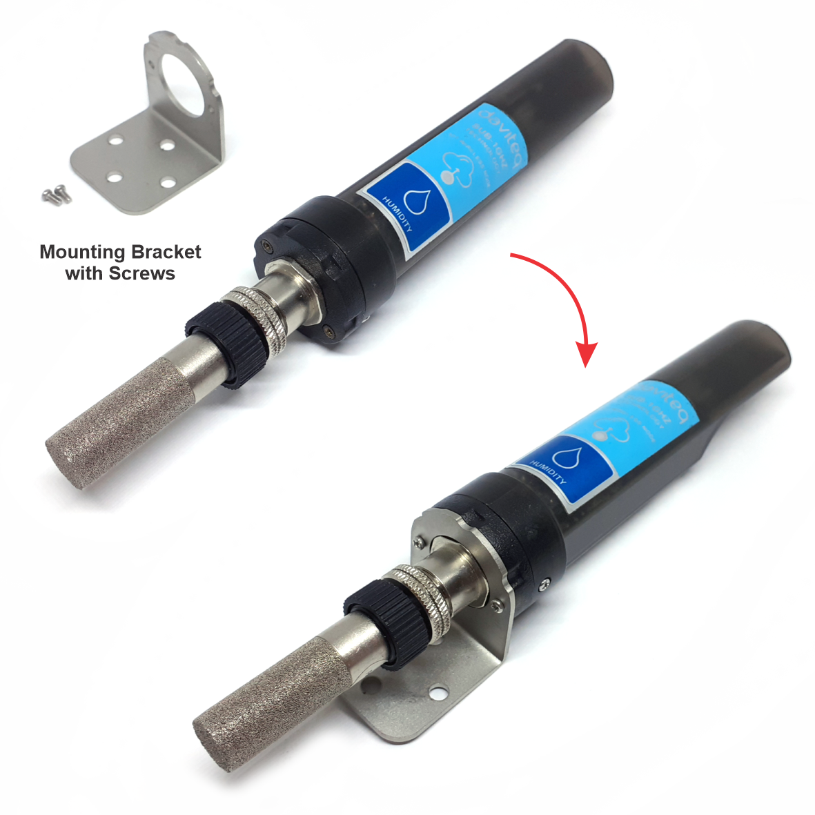
Locate the place where the wireless sensor is mounted, from that locate the position to mount the bracket;
Placing the wireless module on bracket and secure it by 02 x M2 screws (supplied in accessory bag)
Note: The bracket can be mounted on the wireless module in both direction, upward or downward
The mounting bracket is made from hard metallic material. The following steps are for mounting this bracket;
6.1 Reset Sensor Node
6.2 Data rate configuration 625 kps
6.3 Wireless sensor configuration with co-
ordinator
7. Installation
7.1 Mounting bracket installation

The bracket will be fixed on the wall or surface by 2 x M4 screws (supplied by customer) or double-sided 3M tape
(included in accessory bag in carton box);
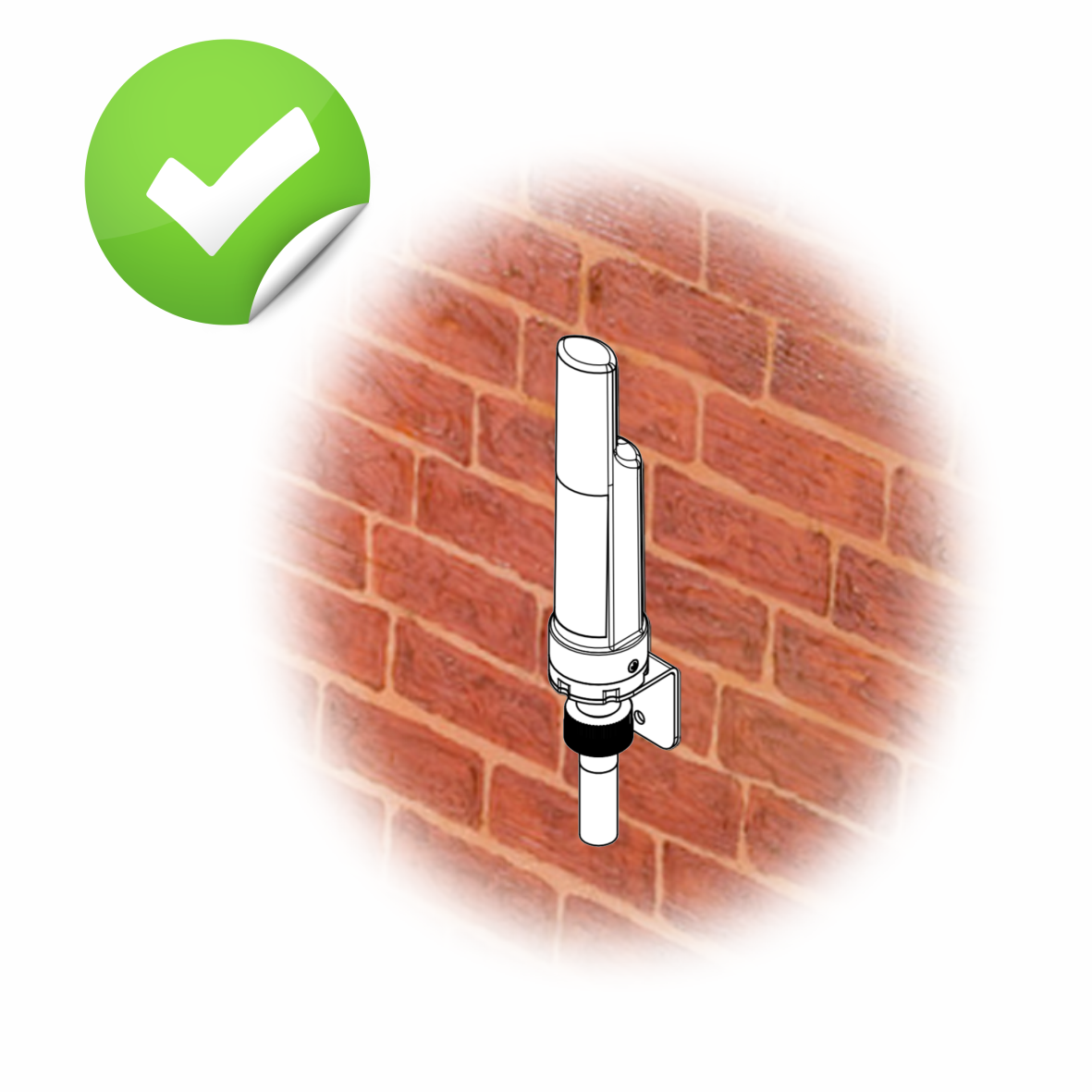
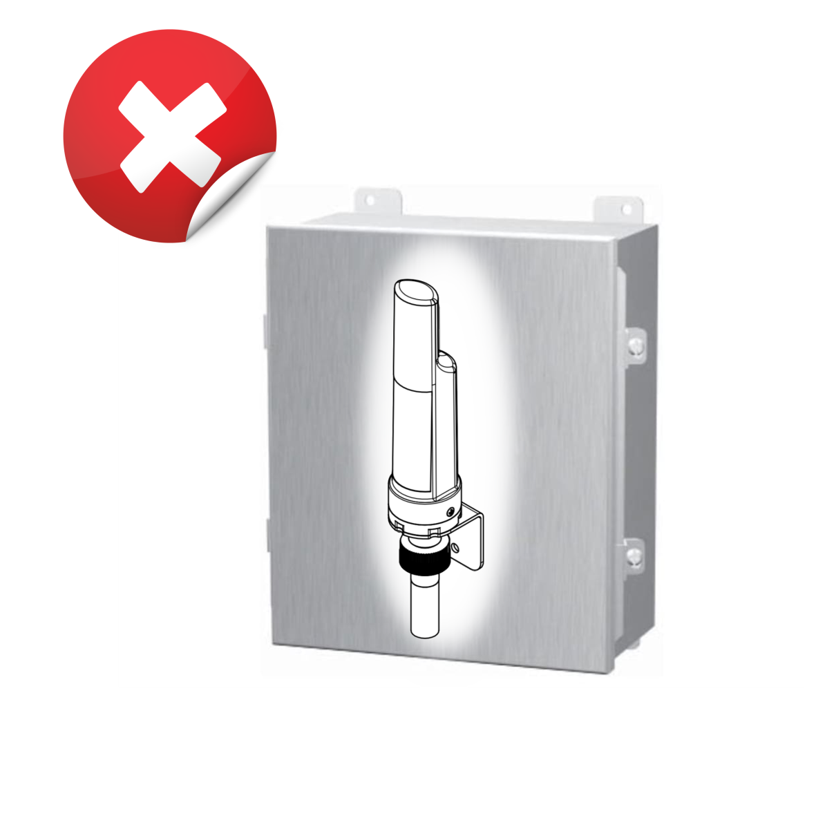
DO NOT install the wireless module inside a complete metallic box or housing. The RF signal can not pass
through metallic wall;
This wireless module would be installed a semi-metallic box, because the RF signal can pass through the non-
metal wall/are;
The best case is to install the wireles module inside or Non-metallic box;
Some non-metallic materials: plastic, glass, wood, leather, concrete, cement…
7.2 Installation location
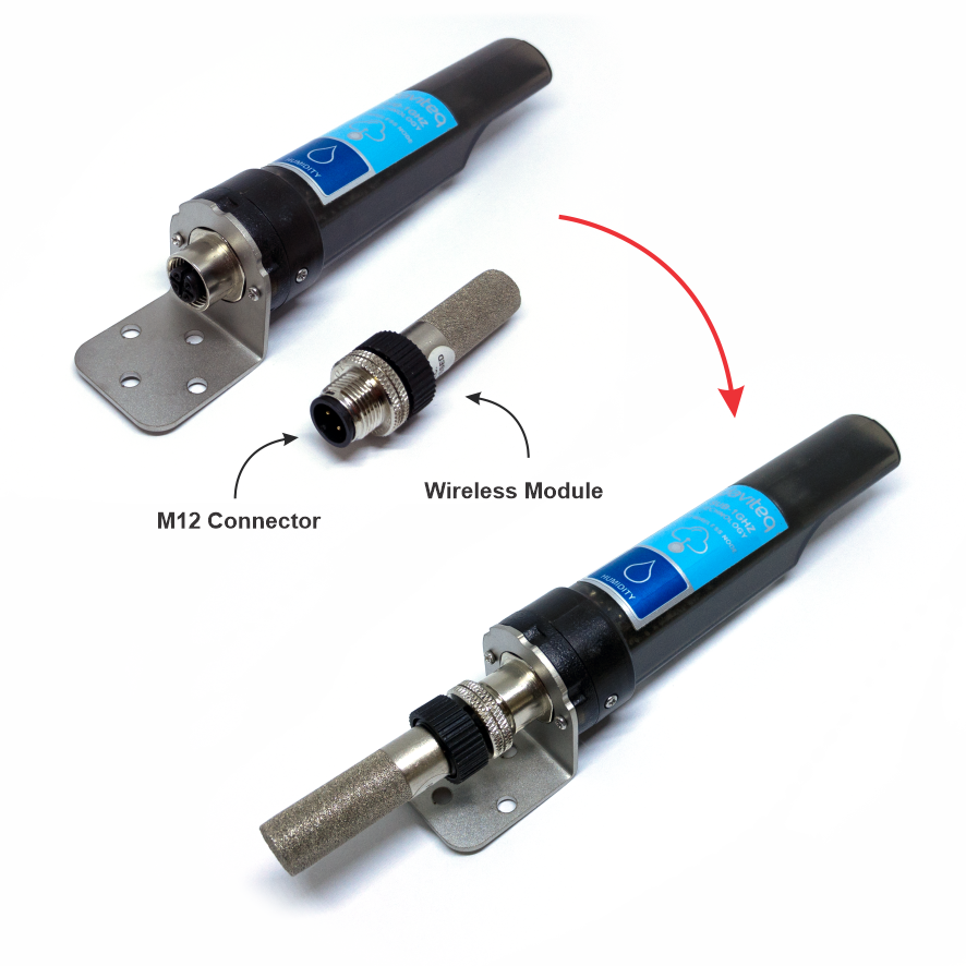
7.3 IO Wiring & Sensor installation

The sensor module has M12-male connector which is matched with M12-female connector on wireless module;
Carefully plug the sensor module onto wireless module, using HAND to tighten slowly until stop;
Note: please DO NOT over tightening by hand or other tool, it can damages the M12 connector;
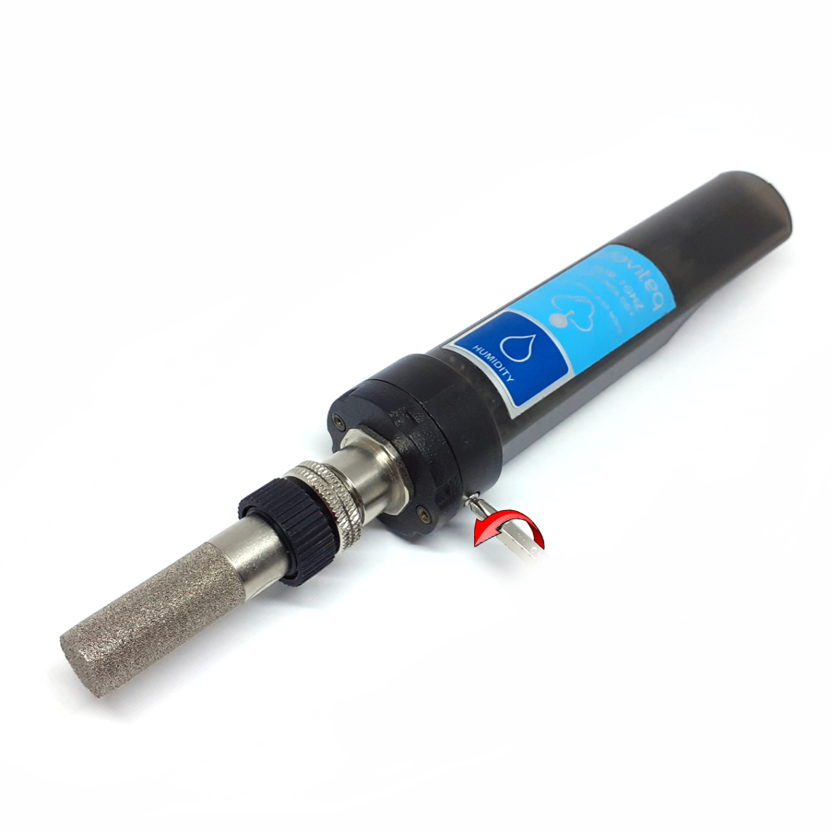
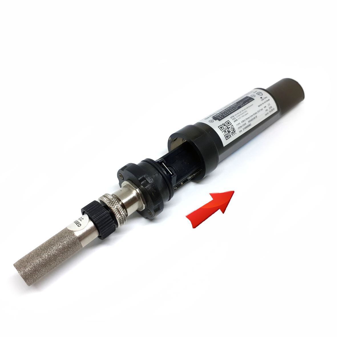
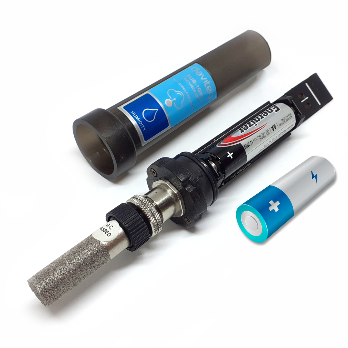
Steps for battery installation:
Using Philips screw driver to unscrew M2 screw at the side of housing
Carefully pull out the top plastic housing in the vertical direction
7.4 Power Supply & Battery installation


No.
Phenomena
Reason
Solutions
1
The status LED of wireless sensor
doesn't light up
No power supply
Configuration function of
the LED is not correct
Check that the battery is
empty or not installed
correctly
Reconfigure the led light
function exactly as
instructed
2
Wireless sensor not connected to
co-ordinator
No power supply
The configuration function
of the RF data rate is
incorrect
Check that the battery is
empty or not installed
correctly
Reconfigure the RF data
rate with the button
according to the
instructions
Manufacturer
Daviteq Technologies Inc
No.11 Street 2G, Nam Hung Vuong Res., An Lac Ward, Binh Tan Dist., Ho
Chi Minh City, Vietnam.
Tel: +84-28-6268.2523/4 (ext.122)
Email: info@daviteq.com | www.daviteq.com
Distributor in Australia and New Zealand
Templogger Pty Ltd
Tel: 1800 LOGGER
Email: contact@templogger.net
Revision #8
Created Thu, Mar 5, 2020 3:02 AM by Kiệt Anh Nguyễn
Updated Mon, Aug 30, 2021 9:04 AM by Kiệt Anh Nguyễn
8. Troubleshooting
9. Support contacts
Table of contents
Other daviteq Measuring Instrument manuals

daviteq
daviteq Sigfox WSSFC-PPS User manual

daviteq
daviteq WSSFC-G4F-NH3 User manual

daviteq
daviteq WS433-MA-31 User manual

daviteq
daviteq MBRTU-SAL User manual

daviteq
daviteq WS433-CO2 User manual

daviteq
daviteq CAP10CNC User manual

daviteq
daviteq MBRTU-TBD User manual

daviteq
daviteq WS433-ULC User manual


