daviteq MBRTU-SAL User manual


JUL-2021
MBRTU-SAL is a salinity sensor based on electrodeless inductive measurement. It uses the generator to generate an
alternating magnetic field in the primary coil to generate an induced current in the medium. The intensity of the
induced current depends on the concentration of ions in the medium. The induced current creates another magnetic
field in the secondary coil. The receiver measures the induced current on the coil to determine the salinity of the
medium. At the same time, the built-in temperature sensor can automatically compensate the temperature, which is
suitable for online long-term monitoring of the environment.
Application scope: Marine, industrial waste water, pharmaceutical, biotechnology, industrial manufacturing and
other online whole process monitoring.
Features
1. Digital sensor, direct output RS-485 digital signal, support Modbus / RTU
2. The built-in temperature sensor can automatically compensate the temperature
3. There is no electrode, so there is no polarization reaction
4. The measurement and the medium are completely electrically isolated, which can be used for high-precision
measurement of heavy and easily precipitated medium or solution with low cost of use and maintenance
5. Low power consumption and anti-interference design of internal circuit
USER GUIDE SALINITY SENSOR
WITH MODBUS RTU OUTPUT
MBRTU-SAL
This document is applied for the following products
1. Introduction

Item
Specifications
Output
Rs-485,MODBUS/RTU
Measuring Method
Non contact electromagnetic principle
Range
0 ~ 70PSU
Accuracy
±1%F.S. or ±0.2PSU(Below 10psu)
Resolution
0.1PSU
Working Environment
0 ~ 65℃; < 0.6MPa
Calibration Method
Two point calibration
Respond Time
10 seconds T90
Temperature Compensation
Automatic temperature compensation(PT1000)
Power Supply
12-24VDC±10%, 10mA;
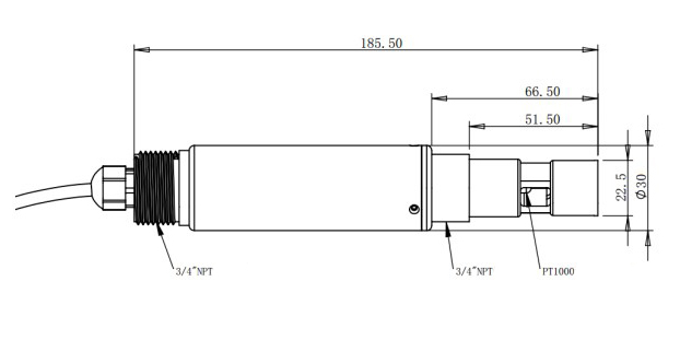
Size
Diameter 30mm; Length 185.5mm;
Protection level
IP68; The water depth is 20 meters; Other customization
Service Life
3 years or above
Cable
5m
Sensor housing material
PVC;PEEK;
2. Specification

Please wiring as shown below:
Wire color
Description
Brown
Power (12-24VDC)
Black
GND
Blue
RS485A
White
RS485B
Bare line
Shielding Layer
Inductive electrode is basically maintenance free; It is recommended to clean up the sensor probe attachment
every 30 days; Avoid the use of hard objects to cause the damage of the light guide part of the measuring probe
during cleaning; Please wipe with a soft damp cloth.
It is recommended to clean the outer surface of the sensor with water flow. If there is still debris residue, please
wipe it with a wet soft cloth.
Installation measurement: avoid the installation measurement at the place where the water flow is turbulent, and
reduce the influence of water bubbles on the measurement. Keep the measuring probe 2cm away from the
bottom.
The probe of the sensor is fouling or attached with more organisms, so the cleaning force can be increased
appropriately. Slight scratch on the probe surface does not affect the normal use of the sensor. But pay attention
not to penetrate the shell of the probe.
Suggestion: the protective cover of our company should be selected to prevent the influence of microbial
attachment on the measurement results.
Problem
Possible Causes
Solution
The operation interface cannot be
connected or the measurement results
are not displayed
Wrong cable connection
Check the wiring mode
4. Wiring
5. Maintenance and Precautions
5.1 Maintenance
5.2 Note
5.3 Other

are not displayed
Wrong sensor address
Check the address for errors
The measured value is too high, too
low or the value is continuously
unstable
The sensor probe is attached by
foreign objects
Clean the sensor probe surface
Other
Contact after sales
The default data format for Modbus communication of this sensor is:
MODBUS-RTU
Baud rate
9600 (default)
Device address
1 (default)
Data bits
8 bit
Parity check
None
Stop bit
1bit
Function code 03: read (R) register value
Function code 06: write (W) single register value
Register
Address
(hex)
Name
R/W
Introductions
Number
of
registers
(byte)
Data
type
0x0100
Temperature
value
R
℃ value x10 (for example: the temperature of 25.6℃ is
displayed as 256, the default is 1 decimal.)
1 (2
bytes)
unsigned
short
0x0101
Salinity value
R
PSU value x10 (for example, the salinity value of 12.1psu is
displayed as 121, with 1 decimal place by default.)
1 (2
bytes)
unsigned
short
0x1000
Temperature
calibration
R/W
Temperature calibration: the written data is the actual
temperature value X10; Read out data is temperature
calibration offset X10.
1 (2
bytes)
unsigned
short
0x1001
Zero point
calibration
R/W
Zero point calibration in air. The data written during
calibration is 0.
1 (2
bytes)
unsigned
short
0x1003
Slope
calibration
R/W
Calibrate in the known standard solution (50% - 100%
range), and write the data as the actual value of the
standard solution × 10.
1 (2
bytes)
unsigned
short
0x2000
Sensor
address
R/W
The default is 1, and the data range is 1-127.
1 (2
bytes)
unsigned
short
0x2003
Baud rate
setting
R/W
The default is 9600. Write 0 is 4800; Write 1 is 9600; Write
2 is 19200.
1 (2
bytes)
unsigned
short
6. Modbus RTU Protocol
6.1 Information frame format
6.2 Register Address

0x2020
Restore
factory
settings
W
The calibration value is restored to the default value and
the written data is 0. Note that the sensor needs to be
calibrated again after reset.
1 (2
bytes)
unsigned
short
unsigned int (unsigned short)
The data consists of two integers.
XXXX XXXX
XXXX XXXX
Byte1
Byte0
Float, According to IEEE 754 (single precision);
The data consists of 1 sign bit, 8-bit exponent, and a 23 bit mantissa .
XXXX XXXX
XXXX XXXX
XXXX XXXX
XXXX XXXX
Byte3
Byte2
Byte1
Byte0
Sign
bit
Exp digit
F decimal
Host send
1
2
3
4
5
6
7
8
ADR
03H
Start register
high byte
Start
register low
byte
Register
number high
byte
Number of
registers low byte
CRC low byte
CRC high byte
The first byte ADR: slave address code (= 001 ~ 254)
Byte 2 03h: read register value function code
Byte 3 and 4: start address of register to be read
To read the FCC instrument,
Bytes 5 and 6: number of registers to read
Bytes 7 and 8: CRC16 checksums from bytes 1 to 6
Slave return
1
2
3
4 , 5
6 , 7
M-1 , M
M+1
M+2
ADR
03H
total
bytes
Register data
1
Register data
2
……
Register data M
CRC low byte
CRC high
byte
The first byte ADR: slave address code (= 001 ~ 254)
6.3 Data structure type
Integer
Float
6.4 Modbus RTU command
6.4.1 Function code 03h: read register value

Byte 2 03h: return to read function code
The third byte: the total number of bytes from 4 to m (including 4 and m)
Bytes 4 to m: register data
Byte m + 1, M + 2: CRC16 check sum from byte 1 to M
When the slave receives an error, the slave returns the error:
1
2
3
4
5
ADR
83H
Information code
CRC low byte
CRC high byte
The first byte ADR: slave address code (= 001 ~ 254)
Byte 2 83h: error reading register value
Byte 3 information code: 01 - function code error
03 - data error
Bytes 4 and 5: CRC16 checksums from bytes 1 to 3
Host send
1
2
3
4
5
6
7
8
ADR
06
Register
high byte
address
Register low
byte
address
Data high
byte
Data low
byte
CRC code
Low byte
CRC code
High byte
When the slave receives correctly, the slave sends back:
1
2
3
4
5
6
7
8
ADR
06
Register
high byte
address
Register low
byte
address
Data high
byte
Data low
byte
CRC code
Low byte
CRC code
High byte
When the slave receives an error, the slave returns:
1
2
3
4
5
ADR
86H
Error code information code
CRC code
Low byte
CRC code
High byte
The first byte ADR: slave address code (= 001 ~ 254)
The second byte 86h: write register value error function code
Byte 3 error code information code: 01 - function code error
03 - data error
Byte 4 and 5: CRC check sum from byte 1 to 3
a) Change slave address:
Address:0x2000 (42001)
6.4.2 Function code 06h: write single register value
6.5 Command example
6.5.1 Default register:

Number of registers: 1
Function code: 0x06
Default sensor address: 01
Change the Modbus device address of the sensor, and change the device address from 01 to 06. The example is as
follows:
Send command: 01 06 20 00 00 06 02 08
Respond: 01 06 20 00 00 06 02 08; Note: the address is changed to 06 and stored after power failure.
b) Baud rate:
Address: 0x2003 (42004)
Number of registers: 1
Function code: 0x06
Default value: 1 (9600bps)
Supported values: 0-2 (4800-19200bps)
The baud rate can be changed by the upper computer setting, and it can work without restart after the change. The
baud rate saves the upper computer setting after power failure. Baud rate support 4800 9600 19200. The baud rate of
integer value allocation is as follows:
Integer
Baud rate
0
4800 bps
1
9600 bps
2
19200 bps
Send command: 01 06 20 03 00 02 F3 CB
Respond: 01 06 20 03 00 02 F3 CB Note: the baud rate is changed to 19200bps and saved after power failure.
a) Measuring temperature command:
Address: 0x0100 (40101)
Number of registers: 1
Function code: 0x03
Read sample values: 19.2℃
Send command: 01 03 01 00 00 01 85 F6
Respond: 01 03 02 00 C0 B8 14
Returns hexadecimal unsigned integer data, temperature value = integer / 10, 1 bit decimal place is reserved.
b) Salinity measurement instruction:
Address: 0x0101 (0x40102)
6.5.2 Function register:

Number of registers: 1
Function code: 0x03
Read sample values: 9.1PSU
Send command: 01 03 01 01 00 01 D4 36
Respond: 01 03 02 00 5B F9 BF
Register returns hexadecimal unsigned integer data, salinity value = integer / 10, 1 decimal place reserved.
c) Continuous reading of temperature and salinity instructions:
Address: 0x0100 (40101)
Number of registers: 2
Function code: 0x03
Read sample values: Temperature 19.2 ℃ and salinity 9.1 PSU
Send command: 01 03 01 00 00 02 C5 F7
Respond: 01 03 04 00 C0 00 5B BB F4
Register returns hexadecimal unsigned integer data, temperature value = integer / 10, 1 decimal place reserved
Register returns hexadecimal unsigned integer data, salinity value = integer / 10, 1 decimal place reserved.
d) Humidity measurement command:
Address: 0x0107 (40108)
Number of registers: 1
Function code: 0x03
Read sample values: relative humidity 40%
Send command: 01 03 01 07 00 01 34 37
Respond: 01 03 02 01 90 B9 B8
Register returns hexadecimal unsigned integer data, humidity value = integer / 10, 1 decimal place reserved.
a) Temperature calibration
Address: 0x1000 (41001)
Number of registers: 1
Function code: 0x06
Calibration example: calibration at 25.8 ° C
Send command: 01 06 10 00 01 02 0D 5B
Respond: 01 06 10 00 01 02 0D 5B
The sensor needs to be calibrated in a constant temperature environment after the temperature indication no longer
6.5.3 Calibration instruction:

fluctuates.
b) Salinity zero calibration
Address: 0x1001 (41002)
Number of registers: 1
Function code: 0x06
Calibration example: calibration in air
Send command: 01 06 10 01 00 00 DC CA
Respond: 01 06 10 01 00 00 DC CA
c) Salinity slope calibration
Address: 0x1003 (41004)
Number of registers: 1
Function code: 0x06
Calibration example: calibration in 50 PSU salinity solution
Send command: 01 06 10 03 01 F4 7D 1D
Respond: 01 06 10 03 01 F4 7D 1D
7. Dimensions
8. Contact

Table of contents
Other daviteq Measuring Instrument manuals

daviteq
daviteq WS433-M12F-ATH User manual

daviteq
daviteq MBRTU-TBD User manual

daviteq
daviteq WS433-MA-31 User manual

daviteq
daviteq WSSFC-G4F-NH3 User manual

daviteq
daviteq Sigfox WSSFC-PPS User manual

daviteq
daviteq WS433-CO2 User manual

daviteq
daviteq WS433-ULC User manual

daviteq
daviteq CAP10CNC User manual
Popular Measuring Instrument manuals by other brands


PCE Instruments
PCE Instruments PCE-PMI 2 manual

EZY SWITCH
EZY SWITCH SMS-4 installation manual

Extech Instruments
Extech Instruments ExStik FL700 user guide

Shodex
Shodex IC SI-50 4E Operation manual

Labino
Labino Apollo 1.0 operating instructions

Thermo Scientific
Thermo Scientific Orion 320 instruction manual


