daviteq WS433-ULC User manual

WS433-ULC-MN-EN-01
MAR-2021
SKU
WS433-ULC
HW Ver.
2.5
FW Ver.
5.0
Item Code
WS433-ULC-01
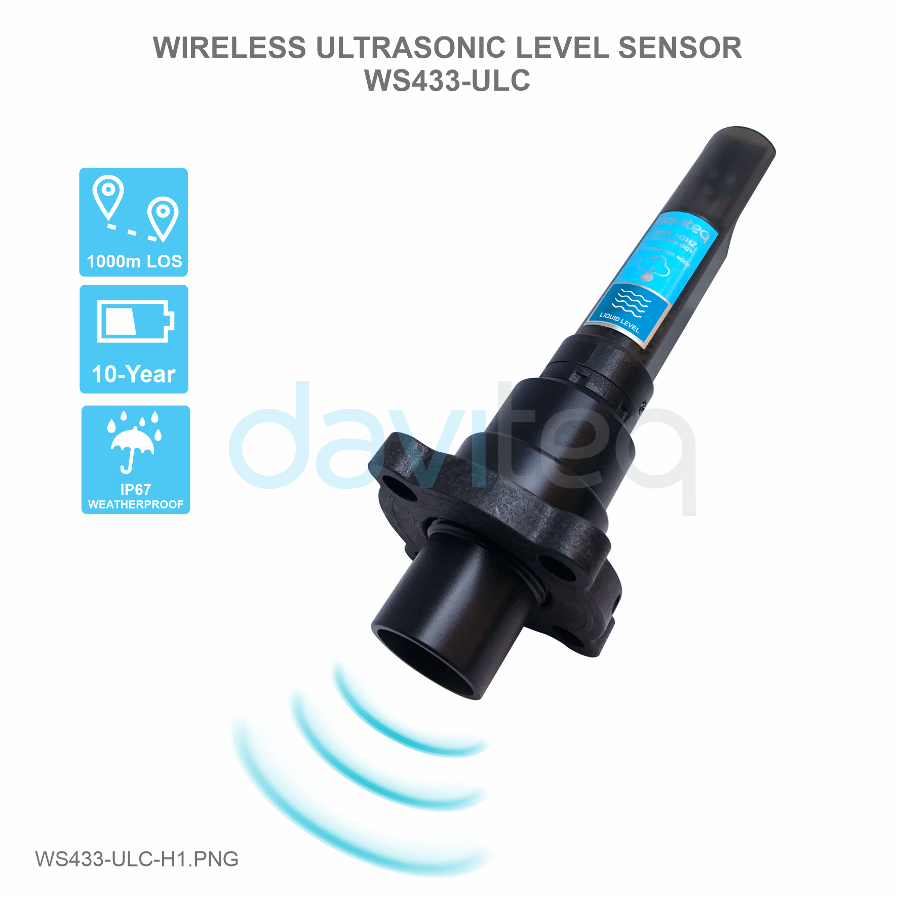
Wireless Ultrasonic Level Sensor Sensor 433MHz, 6000mm range, type AA 1.5VDC battery, IP67
HW Ver.
FW Ver.
Release Date
Functions Change
2.5
5.0
DEC-2019
Change RF data rate by
button
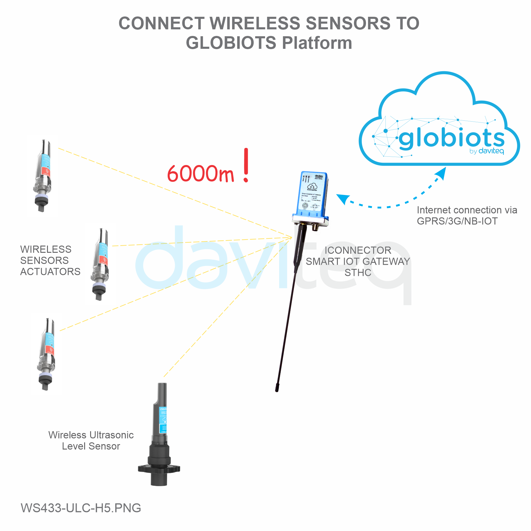
Wireless Ultrasonic Level Sensor is a combination of wireless sensor transmitter WS433-M12F and Ultrasonic level
sensor, measure the level of liquid surface of water, oil ... This level sensor utilises the ultrasonic technology to
measure the surface of liquid or solid, the principle is to measure the time of flight of the ultrasound pulse in the air
environment. The wireless portion is Sub-GHz technology from Texas Instruments allows long range transmission at
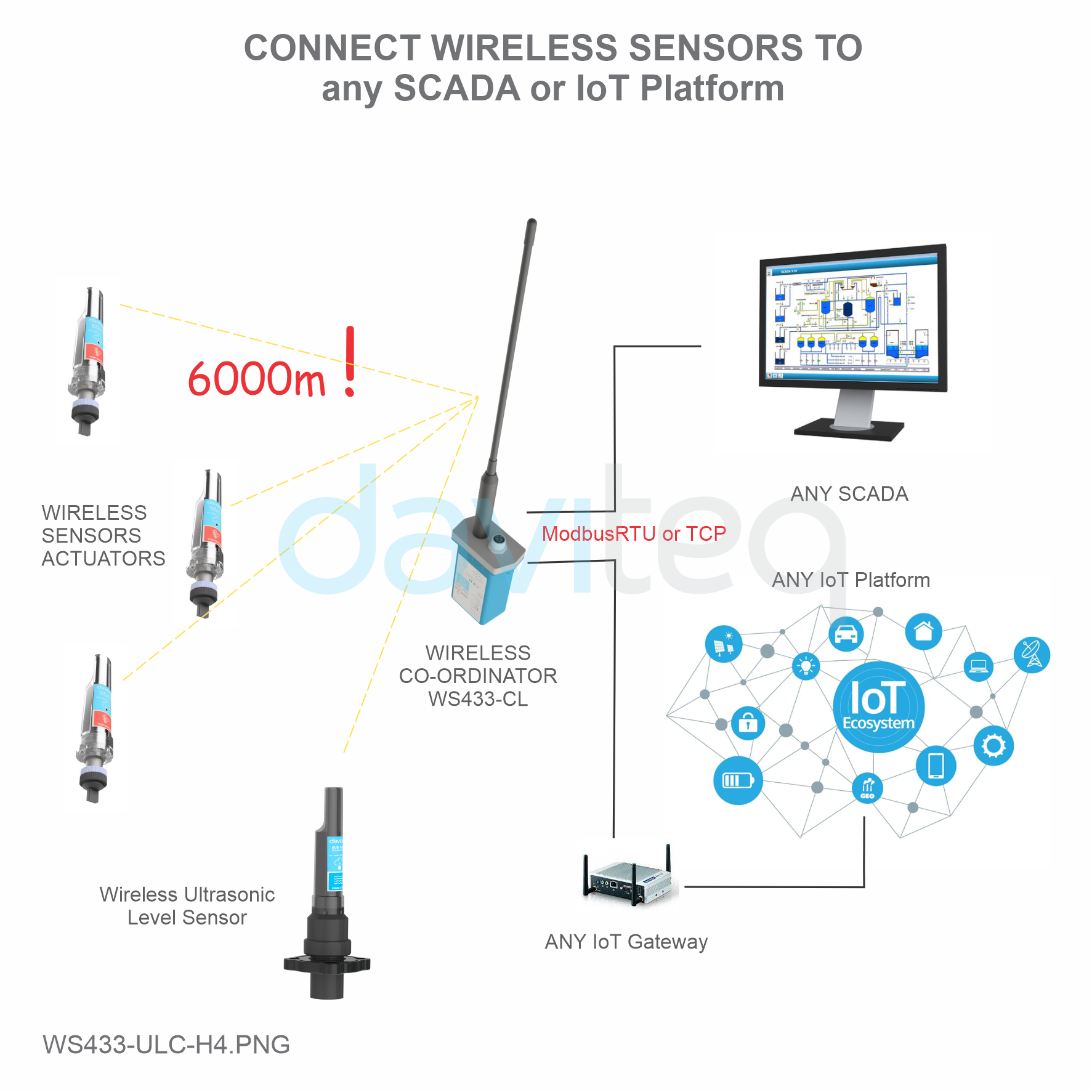
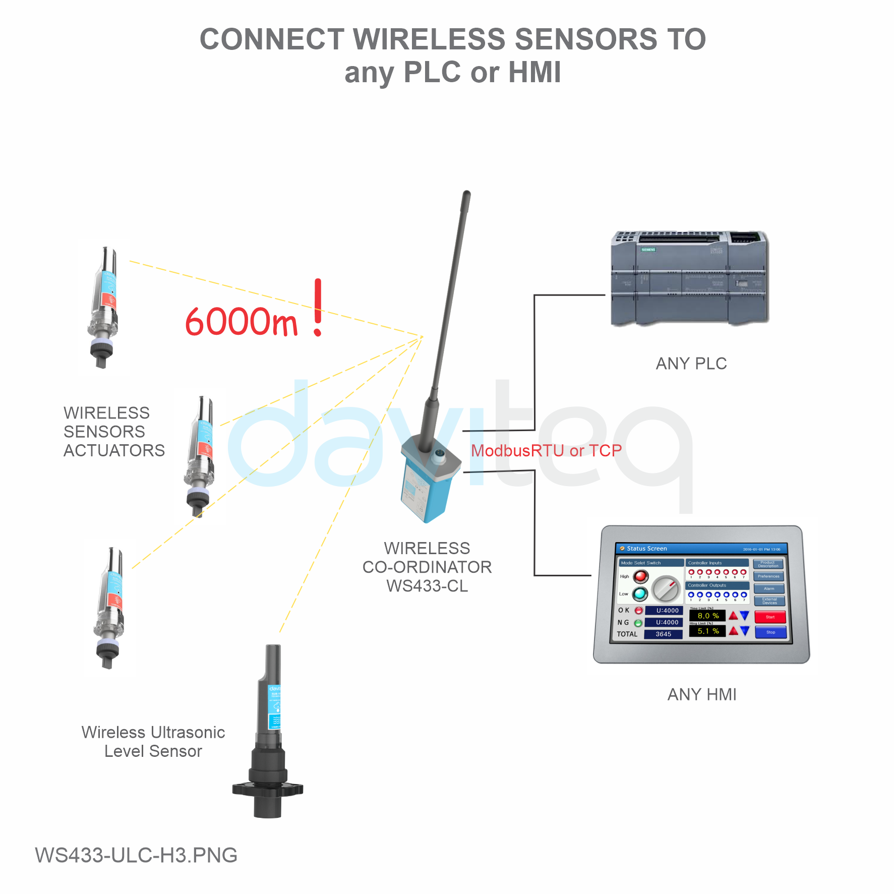
ultra-low power consumption. It will connect 2-way wirelessly to the wireless co-ordinator WS433-CL to send data and
receiving the configuration. It can be configured the operation parameters like data sending interval, health check
cycle...remotely from Globiots platform or via ModbusRTU software (thru the WS433-CL). Its default data rate is 50
kbps, can be switched to 625 bps to increase the communication range. It can last up to 10 years with a single AA
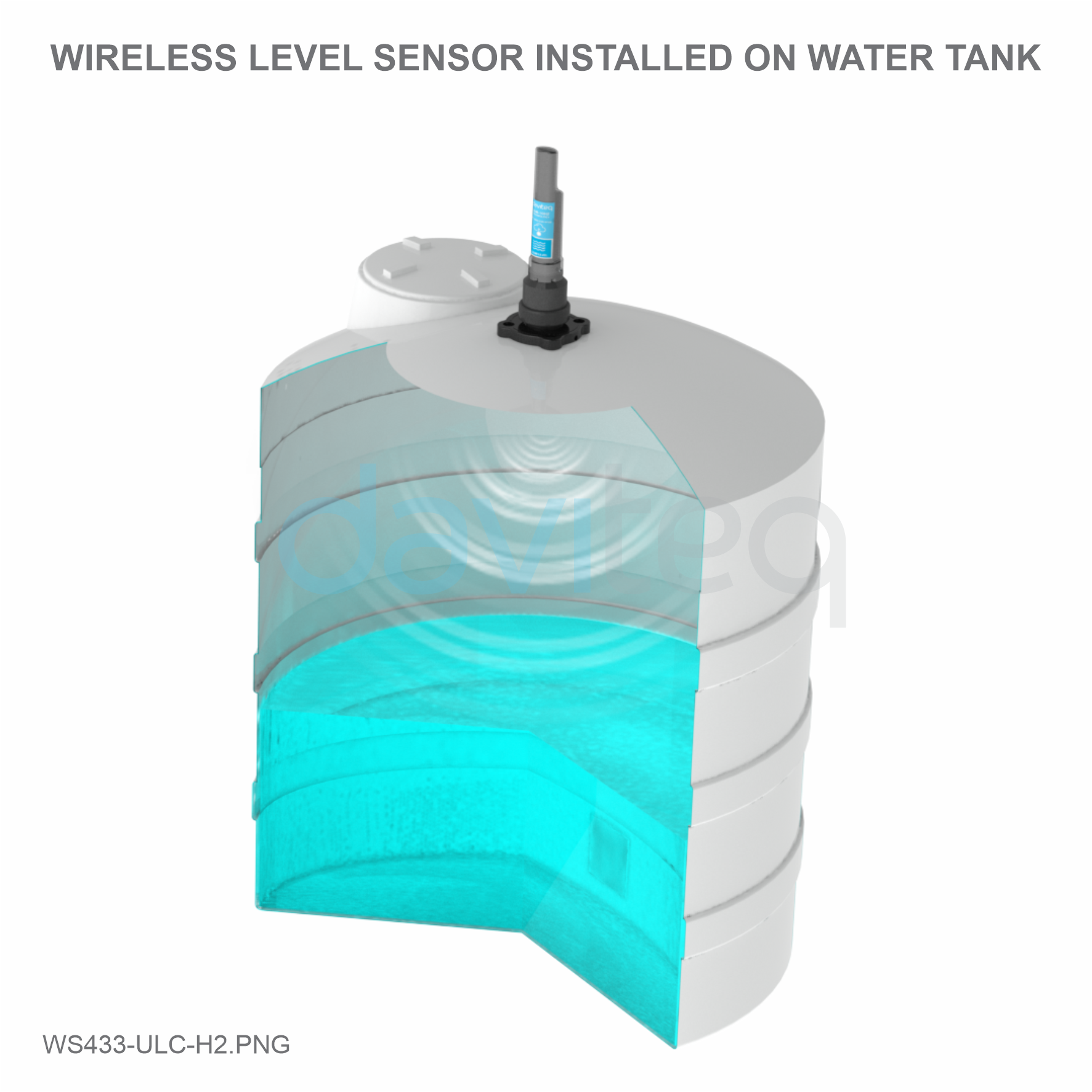
battery. There are many applications such as monitoring of river water levels, water tanks, etc.
USER GUIDE FOR WIRELESS
ULTRASONIC LEVEL SENSOR
WS433-ULC
This document is applied for the following products
1. Functions Change Log
2. Introduction

SENSORS SPECIFICATION:
Sensor
Ultrasonic sensor
Measurement range
280 .. 7500 mm
Resolution
±5.0mm
Accuracy
±10 mm + S*0.3% (with S is the measured value)
Sensor sampling rate
configurable from 10s up to 3600s
Alarm setting
setting the alarm threshold for calculated value
WIRELESS TRANSMITTER SPECIFICATION:
Data speed
Up to 50kbps
Tranmission distance, LOS
1000m
Antenna
Internal Antenna
Battery
01 x AA 1.5-3.6VDC, up to 10-year operation, depends on configuration
Frequency Band
ISM 433Mhz, Sub-GHz technology from Texas Instrument, USA
International Compliance
ETSI EN 300 220, EN 303 204 (Europe) FCC CFR47 Part15 (US), ARIB
STD-T108 (Japan)
Vietnam Type Approval Certification
QCVN 73:2013/BTTTT, QCVN 96:2015/BTTTT (DAVITEQ B00122019)
3. Specification

Security Standard
AES-128
Operating temperature of PCB
-15°C..+60°C (with AA L91 Energizer)
Housing
Poly-carbonate, IP67
Product dimensions & weight
160x30x30mm, < 250g (without battery)
Box dimension & gross weight
190x50x50mm, < 300g
4. Typical Applications
5. Operation Principle
5.1 The Effective Detection Range

For example: the measurement time is 200mS, after this time, the node will read the value of sensor, node will switch
OFF power supply to external sensor to save energy.
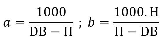
The measured value is the raw value of the sensor. The measured value can be scaled according to the following
formula:
Y = aX + b
The Effective Detection Range
5.2 Process of measurement
5.2.1 Measurement principle of Wireless Sensor
When the sensor sampling time interval is reached, For example 2 minutes, the node will wake up and switch
ON the power supply to supply the energy to external sensor to start the measurement. Depends on the type
and characteristic of external sensor, the sensor will take a certain time to finish the measurement.

X: the raw value from the sensor
Y: the calculated value will be sent to LoRaWAN Gateway in the payload data.
a: constant (default value is 1)
b: constant (default value is 0)
So, if there is no user setting for a and b ==> Y = X
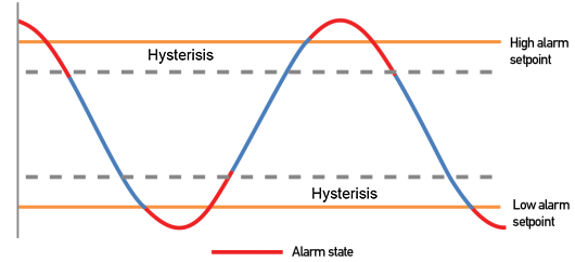
The Y value will be compared with Lo and Hi threshold. Please refer below the graph of alarm processing.
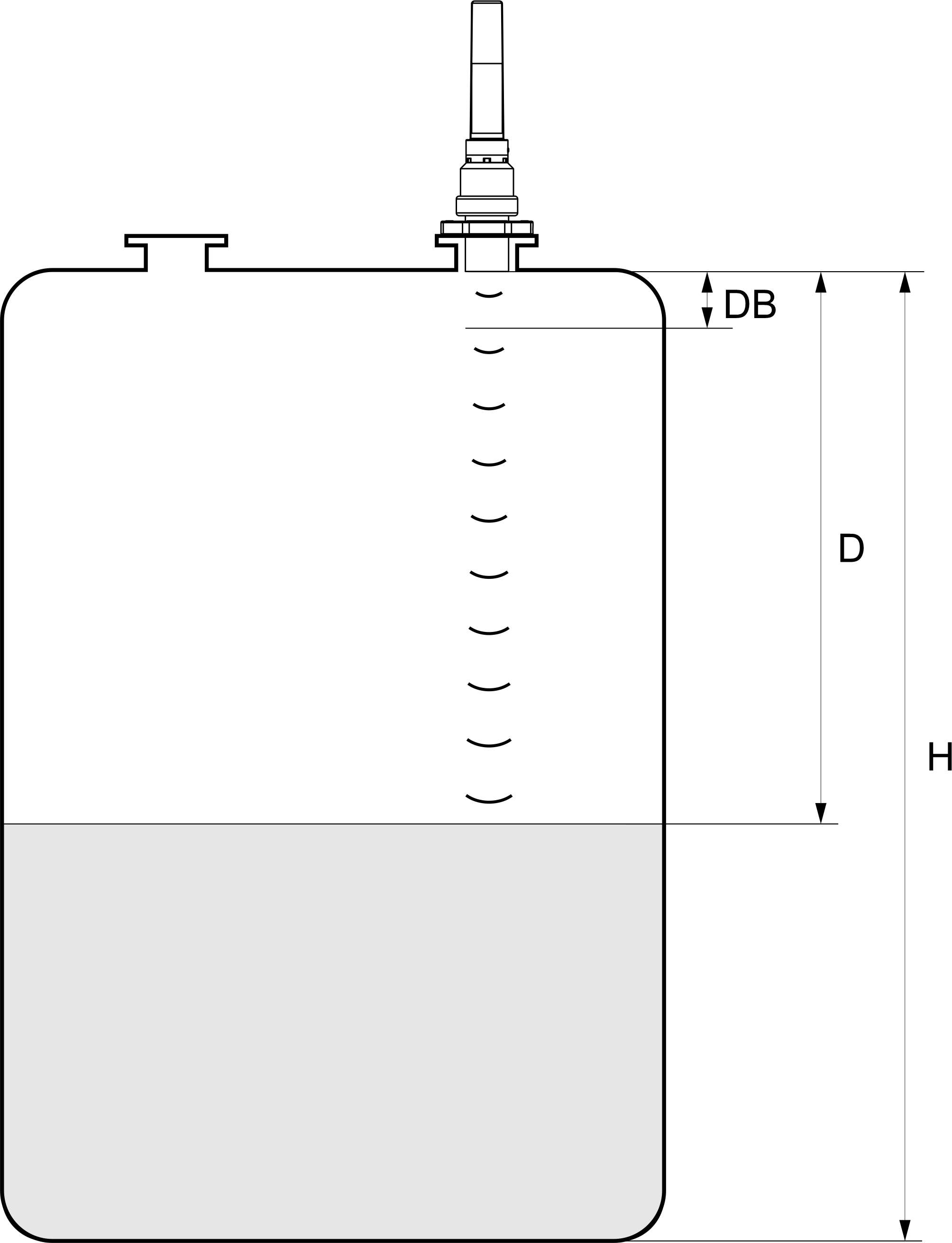
Figure – Ultrasonic Level Transmitter Calibration
DB: Dead band 0..280 mm (This is a short range in front of the ultrasonic sensor can not measure distances)
H: Maximum measuring distance ( Span )
D: Distance
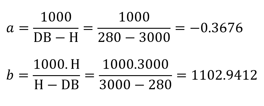
For example: Water tank with maximum height to be measured 3000mm (H) and Dead band (DB) is 280 mm, then:
5.2.2 Calibration

From here we can look up the water level corresponding to the measured distance of the sensor by the formula: Y =
aX + b.
Where: X is the measured distance (mm) and Y is the level (‰)
Distance (mm)
Level (‰)
280
1000
500
919
1000
735
1500
552
2000
368
2500
184
3000
0
Use the offline configuration tool to configure sigfox sensor. Write in the sensor the parameters a and b.
Status bytes of sensor Node
Hi-Byte is error code
Error code
Description
0
No error
1
Just exchange the sensor module but node has not been reset ==>
please take out the battery for 20s then install it again to reset node to
recognize the new sensor module
2
Error, sensor port M12F shorted to GND
3
Error, sensor port M12F shorted to Vcc
4
Error, sensor port M12F shorted each other
Lo-Byte is sensor type
Error code
Description
0
No error
1
Just exchange the sensor module but node has not been reset ==>
please take out the battery for 20s then install it again to reset node to
recognize the new sensor module
2
Error, sensor port M12F shorted to GND
3
Error, sensor port M12F shorted to Vcc
4
Error, sensor port M12F shorted each other
if a1 and b1 in sensor are different from a1=1 and b1=0 then write down a1 and b1 numbers in
excel template configuration file
Refer to Section 5.5 for more details.

Step 1: After supplying power the Co-ordinator via M12 connector, the Node ID must be registered within the first 5
minutes, up to 40 WS.
Step 2: Bring the wireless sensor closer to the Co-ordinator's antenna then take off the wireless sensor battery, wait
for 5s then insert the battery again. If:
Buzzer plays 1 peep sound, LED blink 1 time, that means registering Node ID on Co-ordinator successfully.
Buzzer plays 2 peep sounds, LED blink 2 times, that this Node ID is already registered.
Node id added in this way will be written to the smallest node_id_n address which is = 0.
Set Rssi_threshold (see RF MODE CONFIG (in the Modbus Memmap of WS433-CL), default -25): The case if Co-
ordinator is on high position and need to add node sensor. We set the sensor as close as possible and set the
Rssi_threshold to -80, -90 or -100 to increase the sensitivity to allow WS433-CL-04 can add sensors at a longer
distance. After that, perform 2 steps of adding sensors and then reset Rssi_threshold = -25.
Enb_auto_add_sensors configuration (see RF MODE CONFIG (in the Modbus Memmap of WS433-CL)): In case
you do not want to turn off the power WS433-CL, you can set Enb_auto_add_sensors = 1, this way we have 5
minutes to add nodes (add up to 40 nodes) . After 5 minutes Enb_auto_add_sensors will automatically = 0.
http://www.daviteq.com/en/manuals/books/long-range-wireless-co-ordinator-ws433-cl/page/user-guide-
for-long-range-wireless-co-ordinator-ws433-cl
5.3 Add sensors node to Co-ordinator WS433-CL
5.3.1 Add Sensor Node ID automatically
If you do not hear the "Peep" sound, please disconnect the power the co-ordinator, wait a few minute and try
again.
Memmap resgisters
You can download Modbus Memmap of WS433-CL with the following link:
https://filerun.daviteq.com/wl/?id=WBbGm89AToHWyvIyMOc780N1KmjfUr3Y
5.2.2 Add sensor node into WS433-CL-04 (1) through intermediate
WS433-CL-04 (2) and Modbus
In case the sensor need to be added to WS433-CL-04 (1) has been installed in a high position, the
sensor cannot be brought close to WS433-CL-04 (1). For more details:

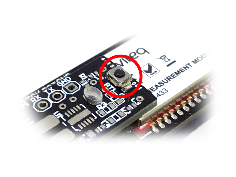
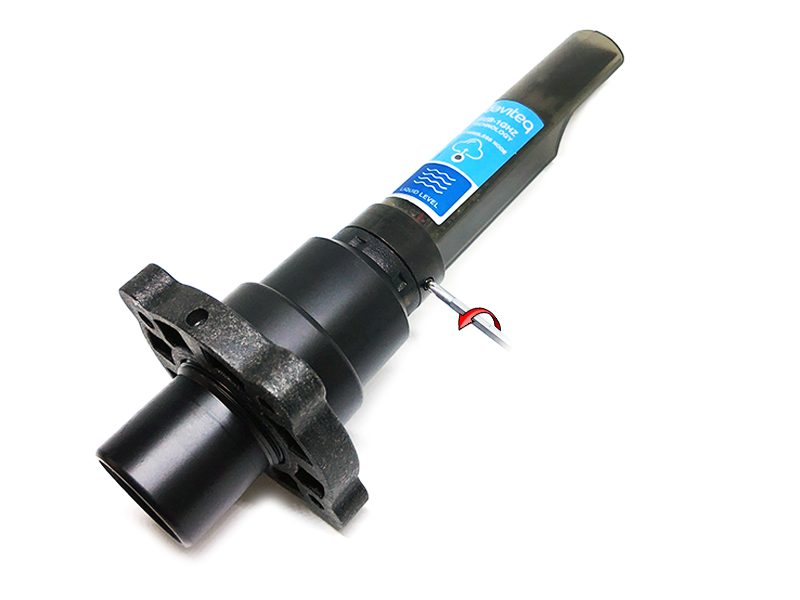
Open the cover of sensor then use the push button to set the data transfer speed for the first 30 seconds when the
battery is first installed, after 30 seconds the push button function does not work.
Press and hold the button for 2 seconds => LED blinks once => Release the button to set Data rate RF 50kbps
Press and hold the button for 5 seconds => LED blinks twice => Release the button to set Data rate RF 625bps
Press and hold the button for 10 seconds => LED blinks 3 times => Release the button to reset RF parameters
(frequency, RF output power, data rate), if held for more than 30 seconds then the button function does not
work.
First, you need to prepare
5.4 Button Function
Reset default WS433:
Frequency: 433.92 MHz
RF transmit power: 15 dBm
RF data rate: 50 kbps
5.5 Configuration
5.5.1 Configuration Offline

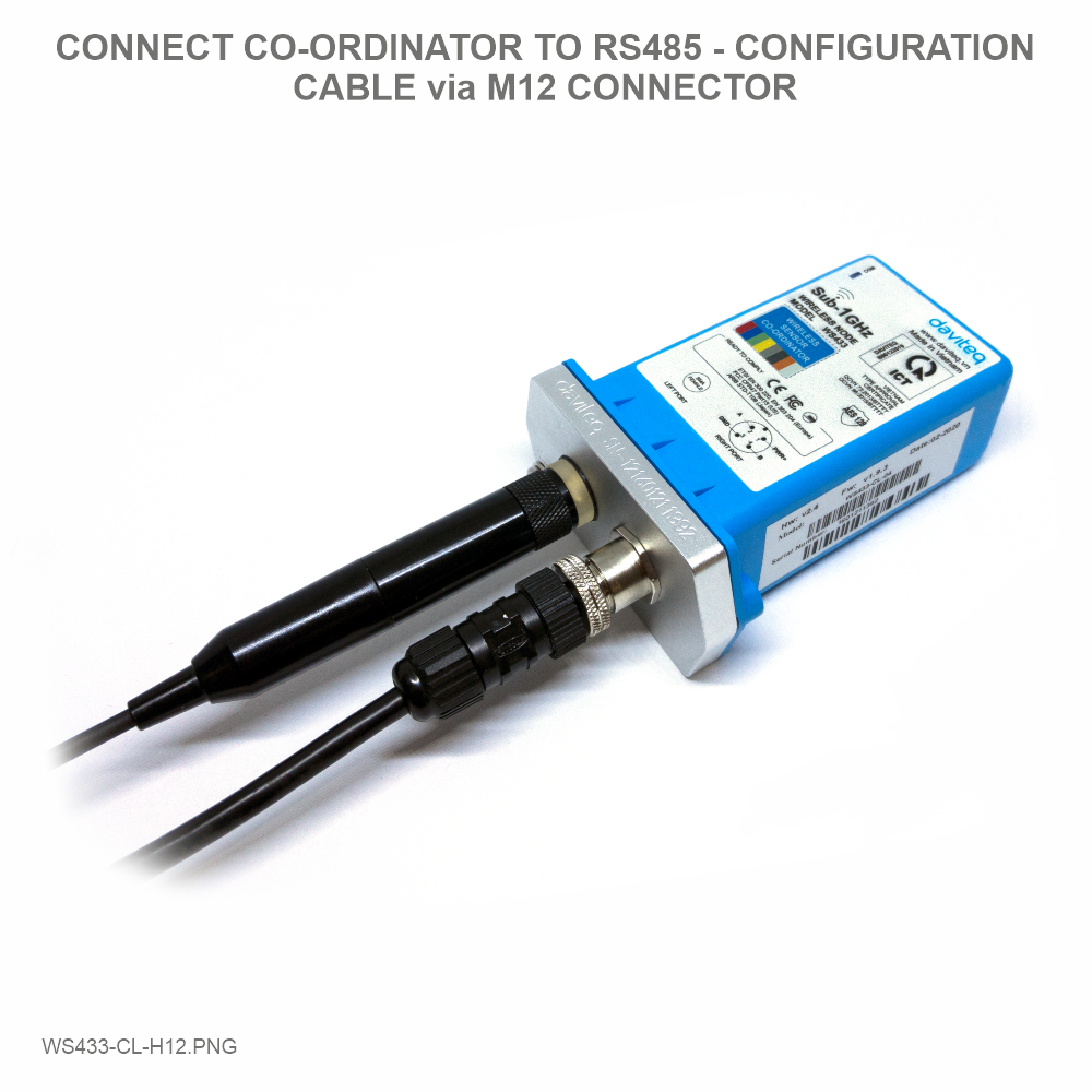
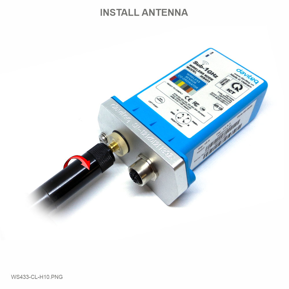
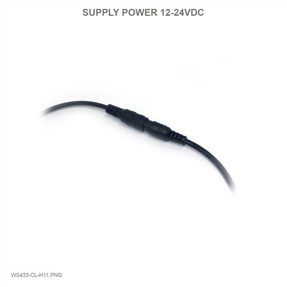
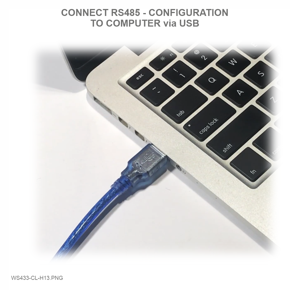
Step 1: Connect Antenna, RS485 - configuration cable and power supply co-ordinator
Num of Node will indicate the number of nodes managed by WS433-CL.
Every time a node is added, the Num of Node will increase by 1.
Every time a node is deleted, the Num of Node is reduced by 1.
Writing Num of Node = 0 will delete all 40 node ids to 0.
If you want to delete a node id, then write it = 0 with the Write function is 16 and the Read function is 3.

Step 2: Open Modbus tool on PC
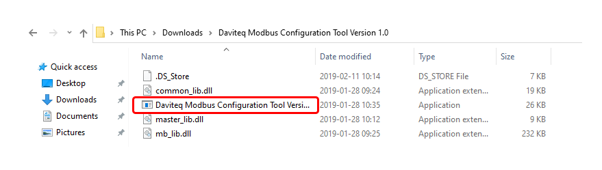
You can download Daviteq Modbus Configuration Tool with the following link:
https://filerun.daviteq.com/wl/?id=qK0PGNbY1g1fuxTqbFW9SXtEvCw7bpc6
Unzip file and run file application "Daviteq Modbus Configuration Tool Version"
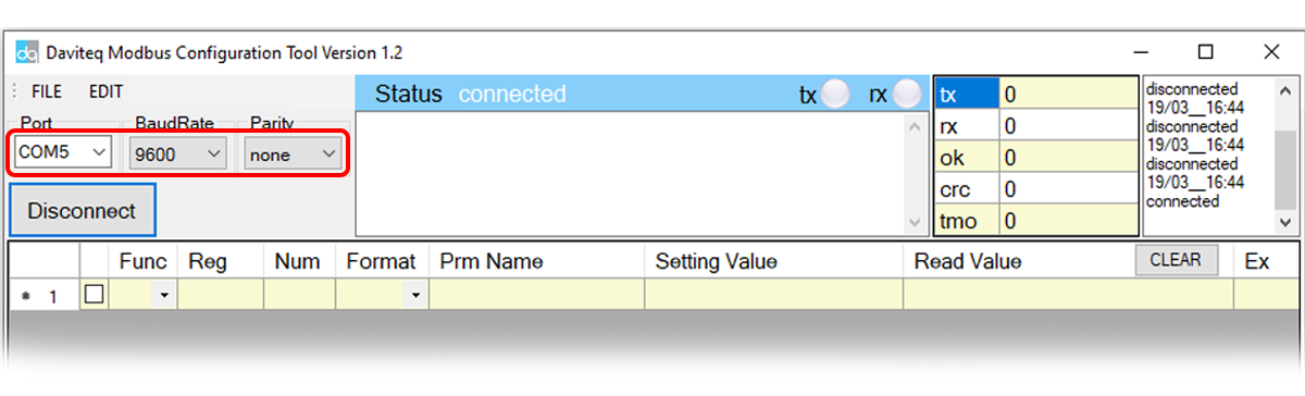
Choose COM Port (the Port which is USB cable plugged in)
Set the BaudRate: 9600, Parity: none
Template File: https://filerun.daviteq.com/wl/?id=hgrjOg3wwvyrvAZ54p8iZiFpDyXTcnec
How to use the Modbus configuration software

Click “ Connect “ untill the Status displays “disconnected” to “connected“. It means the WS433-CL-04 is
being connected with computer;
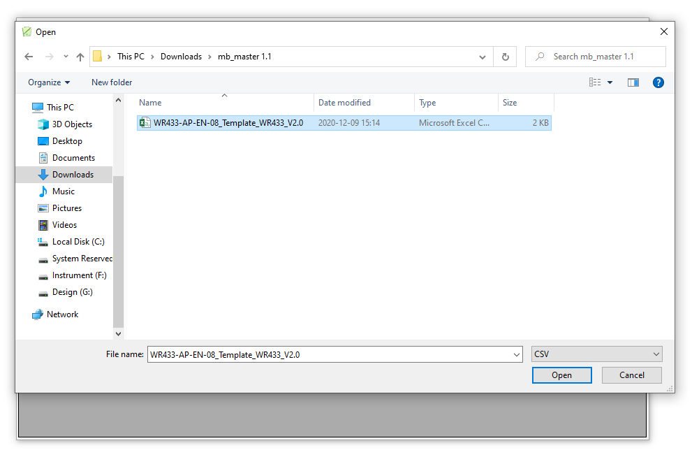
Next, we need to import the configuration file for WS433-CL-04 by importing the csv file: Go to MENU: FILE /
Import New / => select the template file.
Step 3: Configure parameters of the sensor.
In the memmap file, refer to the Memmap of WS433-ULB & ULC sheet to configure the sensor's operating
parameters accordingly.
Function
Code
(Read)
Function
Code
(Write)
# of
register
Byte Size
Description
Value
Range
Default
Format
Property
Explanation
4
1
2
%Battery
of sensor
Node
10,30,60,99
uint16
Read
Battery
level, only
04 levels:
10%, 30%,
60% and
99% (full).
When 10%
==> Need
to replace
the battery
Memmap resgisters
You can download Modbus Memmap of WS433-CL with the following link:
https://filerun.daviteq.com/wl/?id=BKEaUzdArkoc0Hc7nfpRShdPVToVrqQZ
The reference memmap addresses are based on the order of the sensors added in the Memmap file
above
5.5.2 Typical sensor parameters:

4
2
4
Level value
of sensor
Node
(parameter
1)
float
Read
Value from
ultrasonic
level
sensor. This
value is
parameter
1 of a
wireless
sensor node
4
2
4
Distance
value of
sensor
Node
(parameter
2)
float
Read
Value from
ultrasonic
level
sensor. This
value is
parameter
2 of a
wireless
sensor node
3
1
2
Data status
of Node
0-9, 99
byte
Read
0-9:
Interval
updated
data
99:
Disconnected
3
1
2
RF Signal
strength of
Node
0-4
byte
Read
From 0 to 4
with 0 is
being lost
connection
RF and 4 is
the
strongest
RF
3
16
1
2
Cycle_wakeup
1-3600(s)
120
uint16
Read/Write
Every time
interval of
Cycle_wakeup,
sensor node
would ONLY
send data
to co-
ordinator if
the new
measured
value was
changed
more than
the Delta
value of the
last
measured
value.
Default
Cycle_wakeup
is 120
seconds
(Recommended
: 900
seconds)
3
16
1
2
Cycle_healthsta
60-7200(s)
600
uint16
Read/Write
Every time
interval of
Cycle_healthsta,
sensor node
will
absolutely
send data
to co-
ordinator
regardless
any
condition
3
16
2
4
Radio
frequency
433.05-
434.79, 433
Mhz
433.92
float
Read/Write
Configure
the
operating
frequency
of wireless
sensor by
Co-
ordinator,
should be
configured
from
433.05-
434.79
MHz, only
for
advanced
users

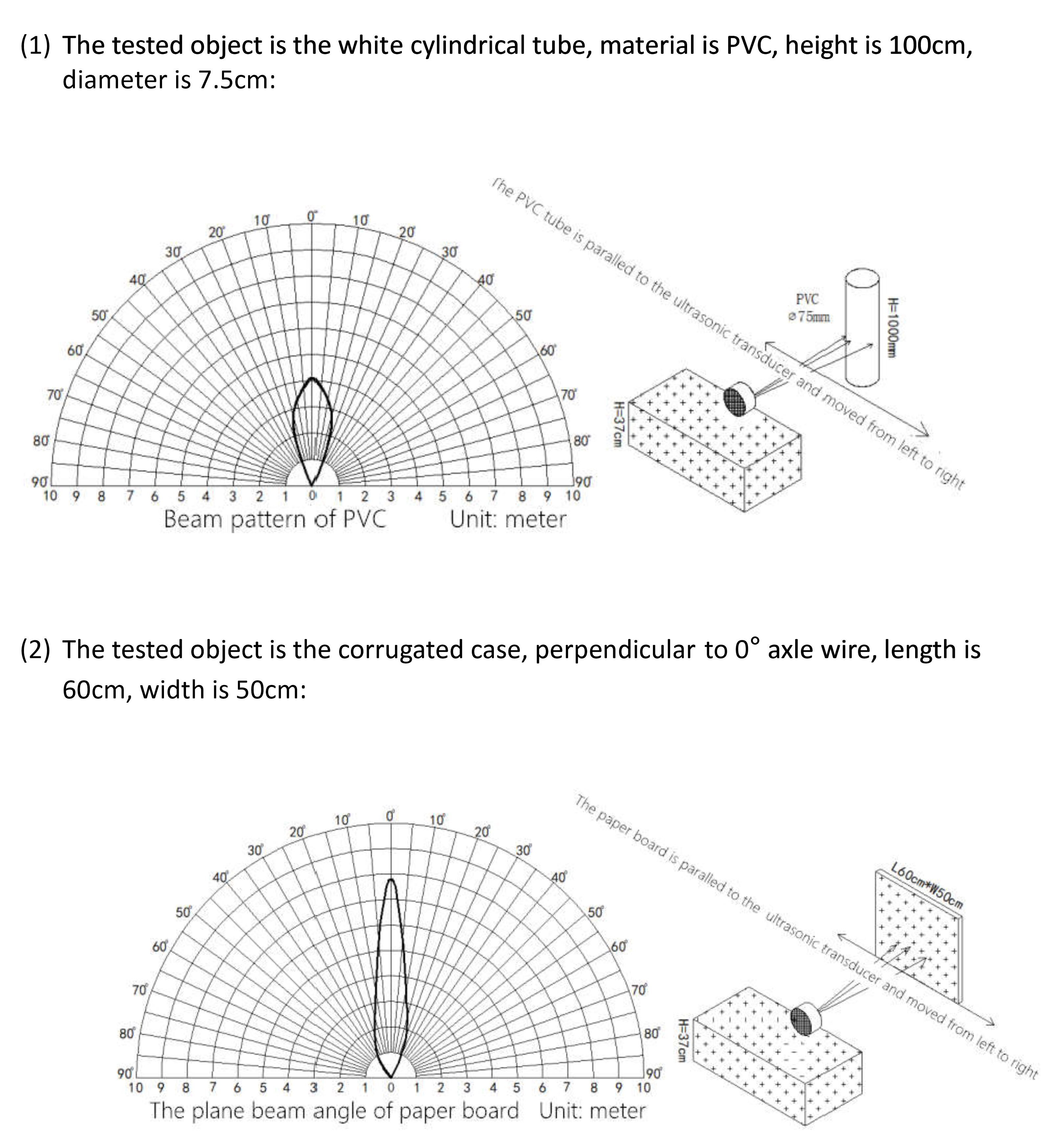
Wireless sensor utilize the ultra-low power 433Mhz RF signal to transmit/receive data with Wireless co-ordinator.
To maximize the distance of transmission, the ideal condition is Line-of-sight (LOS) between the Wireless sensor and
Gateway. In real life, there may be no LOS condition. However, the two modules still communicate each other, but the
distance will be reduced significantly.
6. Installation
6.1 Installation location
ATTENTION:
DO NOT cover the Wireless sensor or its antenna inside a completed metallic box or housing, because the RF
signal can not pass through the metallic material.
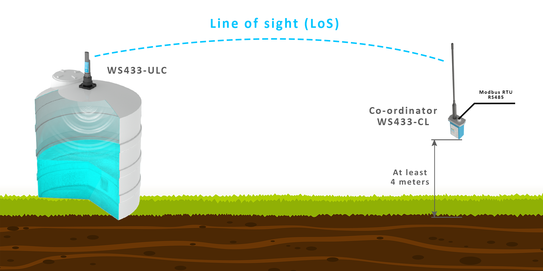
NOTE:
Integrated WS433-CL / iConnector Coordinator The coordinator must be placed at least 4 meters above the
ground and the WS433-ULC clearly visible.
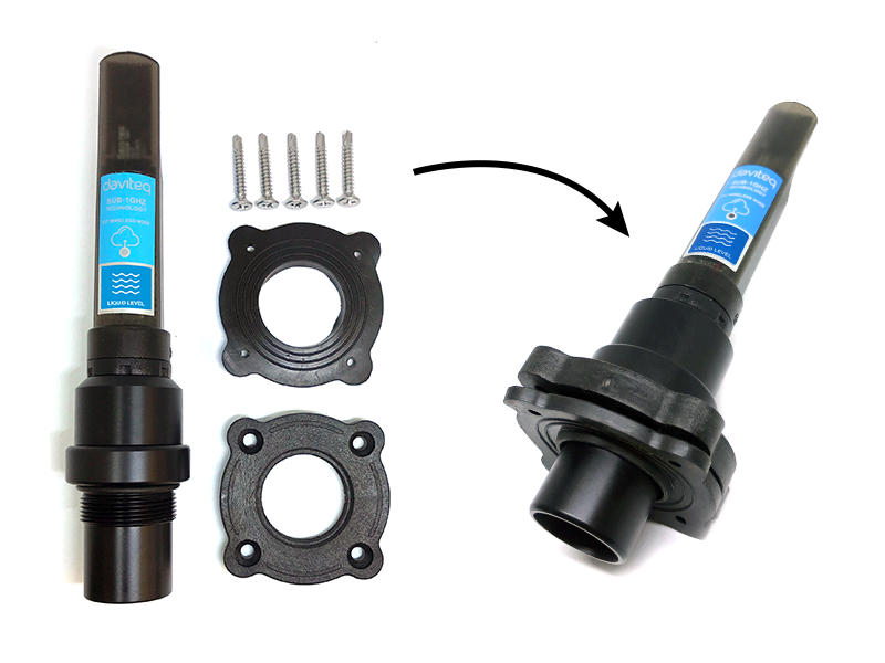
6.2 Process mounting
WARNINGS:
1. Please make sure the fluid is suitable with the wetted materials of the sensor. Please refer sensor
specification;
2. Please make sure that the operating ambient temperature is right for the sensor. Please refer to the sensor's
specifications;
3. Prepare the professional tools for installation. The inappropriate tools may cause damage to the sensor.


Step 3: Insert the top plastic housing and locking by M2 screw
No.
Phenomena
Reason
Solutions
1
The status LED of wireless sensor
doesn't light up
No power supply
Configuration function of
the LED is not correct
Check that the battery is
empty or not installed
correctly
Reconfigure the led light
function exactly as
instructed
2
Wireless sensor not connected to
co-ordinator
No power supply
The configuration function
of the RF data rate is
incorrect
Check that the battery is
empty or not installed
correctly
Reconfigure the RF data
rate with the button
according to the
instructions
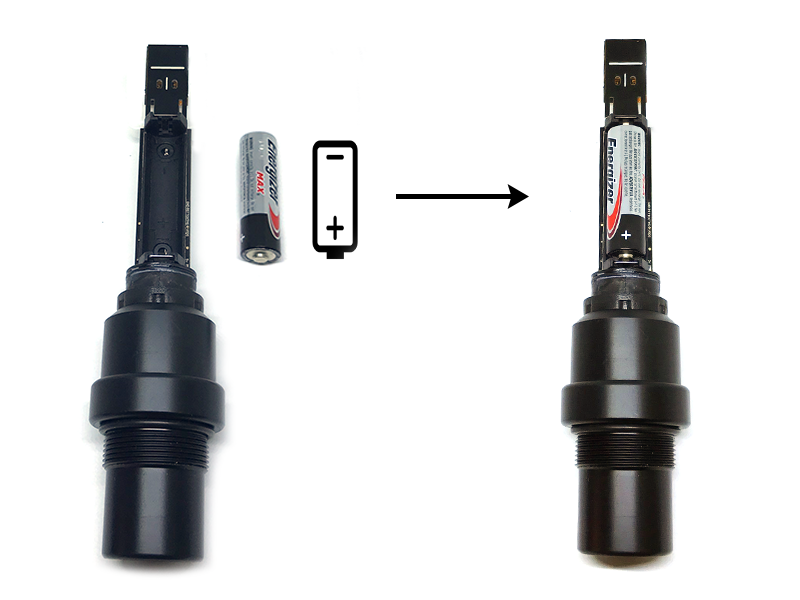
Because of O-ring, it requires to have much pulling force at the beginning, therefore please do it carefully to
avoid the damage of circuit board which is very thin (1.00mm);
REVERSED POLARITY OF BATTERIES IN 10 SECONDS CAN DAMAGE THE SENSOR CIRCUIT !
7. Troubleshooting
8. Support contacts

Manufacturer
Daviteq Technologies Inc
No.11 Street 2G, Nam Hung Vuong Res., An Lac Ward, Binh Tan Dist., Ho
Chi Minh City, Vietnam.
Tel: +84-28-6268.2523/4 (ext.122)
Email: info@daviteq.com | www.daviteq.com
Distributor in Australia and New Zealand
Templogger Pty Ltd
Tel: 1800 LOGGER
Email: contact@templogger.net
Revision #10
Created Fri, Mar 26, 2021 1:37 AM by Kiệt Anh Nguyễn
Updated Mon, Aug 30, 2021 10:24 AM by Kiệt Anh Nguyễn
Table of contents
Other daviteq Measuring Instrument manuals

daviteq
daviteq CAP10CNC User manual

daviteq
daviteq WS433-MA-31 User manual

daviteq
daviteq WS433-CO2 User manual

daviteq
daviteq MBRTU-TBD User manual

daviteq
daviteq Sigfox WSSFC-PPS User manual

daviteq
daviteq WSSFC-G4F-NH3 User manual

daviteq
daviteq MBRTU-SAL User manual

daviteq
daviteq WS433-M12F-ATH User manual
Popular Measuring Instrument manuals by other brands


Koeng
Koeng KEG-500 Operation manual

Teledyne
Teledyne HASTINGS 200 Series instruction manual

PDi
PDi DP-110 Operation manual

agratronix
agratronix MT-PRO+ Operator's manual

M-Life
M-Life B.BEAT PRO16 quick start guide

EUTECH INSTRUMENTS
EUTECH INSTRUMENTS ECOSCAN CON TDS 5 CONDUCTIVITY PORTABLE... Mode d'emploi


