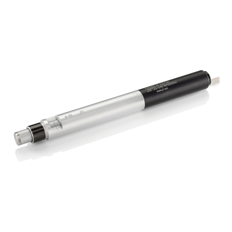
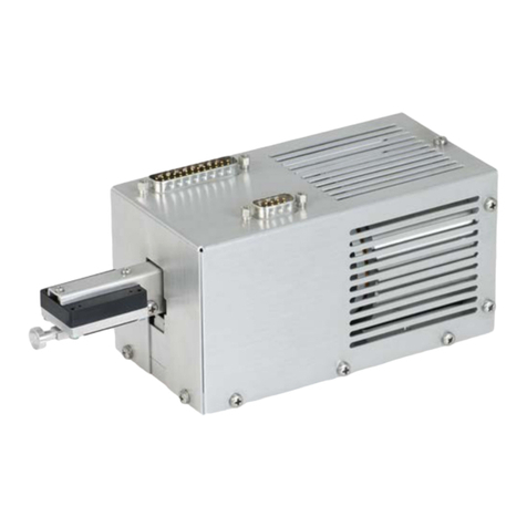
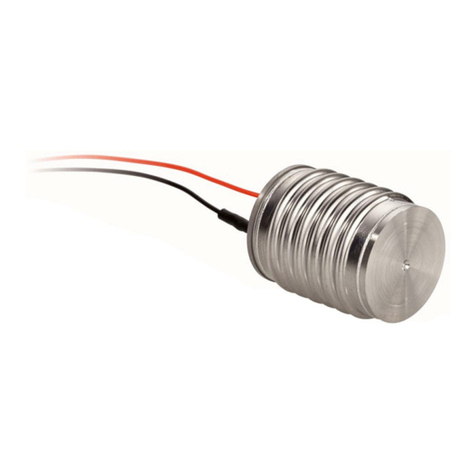
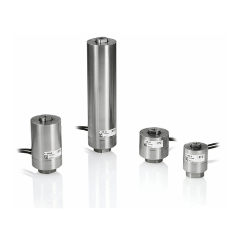
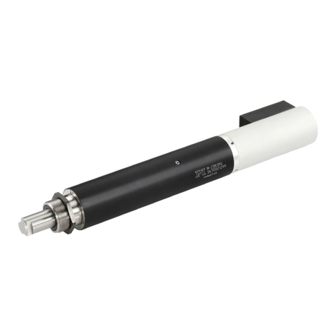
PI M-228 Series User manual

Physik Instrumente (PI) GmbH & Co. KG, Auf der Roemerstrasse 1, 76228 Karlsruhe, Germany
Phone +49 721 4846-0, Fax +49 721 4846-1019, Email info@pi.ws, www.pi.ws
MP86E
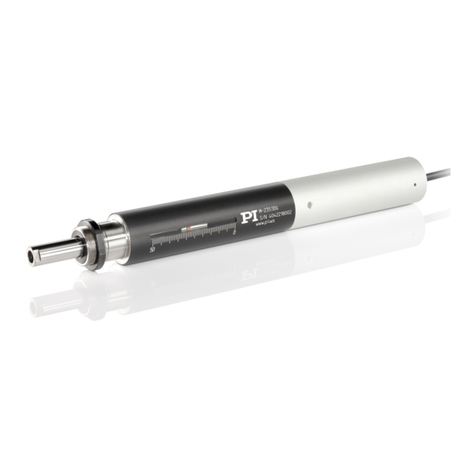
M-228 / M-229 Linear Actuators
User Manual
Version: 2.0.0
Date: 22.01.2021
This document describes the following products:
M-228.10S
Linear actuator, 10 mm, stepper motor, limit
switches
M-228.11S
Linear actuator, 10 mm, stepper motor, direct
drive, limit switches
M-229.25S
Linear actuator, 25 mm, stepper motor, limit
switches
M-229.26S
Linear actuator, 25 mm, stepper motor, direct
drive, limit switches

The following company names and brands are registered trademarks of Physik Instrumente (PI) GmbH & Co.
KG:
PI®, NanoCube®, PICMA®, PILine®, NEXLINE®, PiezoWalk®, NEXACT®, Picoactuator®, PInano®, PIMag®,
Q-Motion®
The patents held by PI are found in our patent list: https://www.physikinstrumente.com/en/about-pi/patents
Notes on brand names and third-party trademarks:
BiSS is a registered trademark of iC-Haus GmbH.
© 2021 Physik Instrumente (PI) GmbH & Co. KG, Karlsruhe, Germany. The text, photographs, and drawings in
this manual are protected by copyright. With regard thereto, Physik Instrumente (PI) GmbH & Co. KG retains
all the rights. The use of any text, images and drawings is permitted only in part and only when indicating the
source.
Original instructions
First printing: 22.01.2021
Document number: MP86E, CBo, Version 2.0.0
Subject to change. This manual is superseded by any new release. The latest respective release is available for
download (p. 3) on our website.

1About this Document 1
1.1 Objective and Target Audience of this User Manual.................................................. 1
1.2 Symbols and Typographic Conventions...................................................................... 1
1.3 Figures ........................................................................................................................ 2
1.4 Other Applicable Documents ..................................................................................... 2
1.5 Downloading Manuals................................................................................................ 3
2Safety 5
2.1 Intended Use .............................................................................................................. 5
2.2 General Safety Instructions ........................................................................................ 5
2.2.1 Organizational Measures............................................................................... 6
2.2.2 Safety Measures During Installation.............................................................. 6
2.2.3 Safety Measures when Starting and Operating............................................. 7
2.2.4 Safety Measures During Maintenance .......................................................... 7
3Product Description 9
3.1 System Overview........................................................................................................ 9
3.2 Model Overview ....................................................................................................... 10
3.3 Product View ............................................................................................................ 11
3.4 Product Labeling....................................................................................................... 11
3.5 Scope of Delivery...................................................................................................... 12
3.6 Suitable Controllers .................................................................................................. 12
3.7 Accessories ............................................................................................................... 12
3.8 Technical Features.................................................................................................... 13
3.8.1 Limit Switches .............................................................................................. 13
3.8.2 Reference Switch......................................................................................... 13
4Unpacking 15
5Installation 17
5.1 General Notes on Installing ...................................................................................... 17
5.2 Changing the Tip....................................................................................................... 18
5.3 Providing a Suitable Mechanical Mounting and Installation Environment.............. 20
5.4 Installing the M-228 / M-229 in a Mechanical Mounting ........................................ 21
5.5 Connecting the M-228 / M-229 to the Controller.................................................... 23
6Startup 25
6.1 General Notes on Startup......................................................................................... 25
Contents

6.2 Starting and Operating the Actuator........................................................................ 27
6.3 Operating Parameters .............................................................................................. 27
7Maintenance 29
7.1 General Notes on Maintenance ............................................................................... 29
7.2 Lubricating the M-228 / M-229 ................................................................................ 29
7.3 Cleaning the M-228 / M-229 .................................................................................... 30
8Troubleshooting 31
9Customer Service 33
10 Technical Data 35
10.1 Specifications............................................................................................................ 35
10.1.1 Data Table.................................................................................................... 35
10.1.2 Maximum Ratings........................................................................................ 36
10.1.3 Ambient Conditions and Classifications ...................................................... 37
10.1.4 Limit Switch Specifications .......................................................................... 37
10.1.5 Reference Switch Specifications.................................................................. 37
10.2 Dimensions ............................................................................................................... 38
10.2.1 M-228.10S.................................................................................................... 38
10.2.2 M-228.11S.................................................................................................... 38
10.2.3 M-229.25S.................................................................................................... 39
10.2.4 M-229.26S.................................................................................................... 39
10.2.5 M23010116 Flat Tip..................................................................................... 40
10.2.6 M23010117 Ball Tip..................................................................................... 40
10.3 Pin Assignment ......................................................................................................... 41
11 Old Equipment Disposal 43
12 EU Declaration of Conformity 45

1 About this Document
M--228 / M--229 Linear Actuators MP86E Version: 2.0.0 1
In this Chapter
Objective and Target Audience of this User Manual..................................................................... 1
Symbols and Typographic Conventions ......................................................................................... 1
Figures............................................................................................................................................ 2
Other Applicable Documents......................................................................................................... 2
Downloading Manuals ................................................................................................................... 3
1.1 Objective and Target Audience of this User Manual
This manual contains information on using the M-228 / M-229 as intended.
It assumes that the reader has a fundamental understanding of basic servo systems as well as
motion control concepts and applicable safety procedures.
The latest versions of the user manuals are available for download (p. 3) on our website.
1.2 Symbols and Typographic Conventions
The following symbols and typographic conventions are used in this user manual:
CAUTION
Dangerous situation
Failure to comply could lead to minor injury.
Precautionary measures for avoiding the risk.
NOTICE
Dangerous situation
Failure to comply could cause damage to equipment.
Precautionary measures for avoiding the risk.
INFORMATION
Information for easier handling, tricks, tips, etc.
1
About this Document

1 About this Document
2 Version: 2.0.0 MP86E M--228 / M--229 Linear Actuators
Symbol/Label Meaning
1.
2.
Action consisting of several steps with strict sequential order
Action consisting of one or more steps without relevant sequential order
Bullet
p. 5
Cross-reference to page 5
RS-232
Labeling of an operating element on the product (example: socket of the
RS-232 interface)
Warning sign on the product referring to detailed information in this
manual.
1.3 Figures
For better understandability, the colors, proportions, and degree of detail in illustrations can
deviate from the actual circumstances. Photographic illustrations may also differ and must not
be seen as guaranteed properties.
1.4 Other Applicable Documents
The devices and software tools from PI mentioned in this documentation are described in
separate manuals.
Product Document
C-663.12 Mercury Step stepper motor
controller
MS241 User Manual
C-663.12C885 Mercury Step stepper motor
controller module
C663T0004 User Manual
PIMikroMove
SM148E Software Manual

1 About this Document
M--228 / M--229 Linear Actuators MP86E Version: 2.0.0 3
1.5 Downloading Manuals
INFORMATION
If a manual is missing or problems occur with downloading:
Contact our customer service department (p. 33).
Downloading Manuals
1. Open the website www.pi.ws.
2. Search the website for the product number (e.g., M-228) or the product family (e.g.,
linear actuator with stepper motor).
3. Click the corresponding product to open the product detail page.
4. Click the Downloads tab.
The manuals are shown under Documentation. Software manuals are shown under
General Software Documentation.
5. Click the desired manual and fill out the inquiry form.
The download link will then be sent to the email address entered.


2 Safety
M--228 / M--229 Linear Actuators MP86E Version: 2.0.0 5
In this Chapter
Intended Use.................................................................................................................................. 5
General Safety Instructions............................................................................................................ 5
2.1 Intended Use
The M-228 / M-229 is a laboratory device as defined by DIN EN 61010-1. It is intended to be
used in interior spaces and in an environment which is free of dirt, oil, and lubricants.
In accordance with its design, the M-228 / M-229 is intended to be used for positioning,
adjusting and shifting loads in one axis at various velocities.
It is only possible to use the M-228 / M-229 as intended when it is installed, and only with a
suitable controller (p. 12). The controller is not included in the scope of delivery of the M-228 /
M-229.
2.2 General Safety Instructions
The M-228 / M-229 is built according to state-of-the-art technology and recognized safety
standards. Improper use can result in personal injury and/or damage to the M-228 / M-229.
Use the M-228 / M-229 for its intended purpose only, and only when it is in perfect
technical condition.
Read the user manual.
Eliminate any malfunctions that may affect safety immediately.
The operator is responsible for the correct installation and operation of the M-228 / M-229.
2
Safety

2 Safety
6 Version: 2.0.0 MP86E M--228 / M--229 Linear Actuators
2.2.1 Organizational Measures
User manual
Always keep this user manual together with the M-228 / M-229.
The latest versions of the user manuals are available for download (p. 3) on our
website.
Add all information from the manufacturer to the user manual, for example
supplements or technical notes.
If you give the M-228 / M-229 to a third party, include this user manual as well as other
relevant information provided by the manufacturer.
Do the work only if the user manual is complete. Missing information due to an
incomplete user manual can result in minor injury and damage to equipment.
Install and operate the M-228 / M-229 only after you have read and understood this
user manual.
Personnel qualification
The M-228 / M-229 may only be installed, started, operated, maintained, and cleaned by
authorized and appropriately qualified personnel.
2.2.2 Safety Measures During Installation
A cable break leads to a failure of the linear actuator.
Install the linear actuator so that the cable is not bent too strongly or crushed during
operation.
Lateral forces that affect the pusher of the linear actuator increase the friction on the internal
drive components. Increased friction impairs the motion of the pusher and increases wear on
the drive components.
Avoid lateral forces on the tip and on the pusher of the M-228 / M-229.
The motion of the pusher can be hindered by a mounting nut that has been tightened too
strongly. This reduces the positioning accuracy.
Do not overtighten the nut (torque ≤15 Nm).

2 Safety
M--228 / M--229 Linear Actuators MP86E Version: 2.0.0 7
2.2.3 Safety Measures when Starting and Operating
There is a risk of crushing and minor injuries between the moving pusher of the M-228 / M-229
and a stationary part or obstacle.
Keep your fingers at a safe distance from the motion range of the pusher.
Do not place any objects in areas where they can get caught by the pusher.
The M-228 / M-229 may move unintentionally when connecting it to the controller. Faulty
software and incorrect operation of the software may also cause unintended movements.
Do not place any objects in areas where they can be caught by moving parts.
Before connecting the M-228 / M-229, check whether a macro is defined as the startup
macro in the controller and cancel the selection of the startup macro if necessary.
Connecting a linear actuator to an unsuitable controller can damage the linear actuator or
controller.
Connect a linear actuator with stepper motor to a stepper motor controller only.
The collision of moving parts with the hard stop (end of travel range), as well as high
acceleration, can cause damage to, or considerable wear on the mechanical system.
In the event of a malfunction of the motor controller, stop the motion immediately.
Ensure that the end of the travel range is approached at low velocity.
Set your control signal so that the moving part does not stop abruptly or try to continue
moving at the end of the travel range.
Determine the maximum velocity for your application.
Ensure that the automatic limit switch halt is supported by the controller, or that it is
activated in the controller.
2.2.4 Safety Measures During Maintenance
The M-228 / M-229 is precisely aligned.
Do not loosen any sealed screw.


3 Product Description
M--228 / M--229 Linear Actuators MP86E Version: 2.0.0 9
In this Chapter
System Overview ........................................................................................................................... 9
Model Overview........................................................................................................................... 10
Product View................................................................................................................................ 11
Product Labeling .......................................................................................................................... 11
Scope of Delivery ......................................................................................................................... 12
Suitable Controllers ..................................................................................................................... 12
Accessories................................................................................................................................... 12
Technical Features ....................................................................................................................... 13
3.1 System Overview
The following figure shows an overview of the overall system.
Figure 1: Overall system, overview
To operate the actuator in your application, the following components are necessary:
Component Task Supplied by or available from PI
Peripheral control
equipment
Loads configurations and control
commands into the controller (e.g.,
PC in conjunction with PC
software).
PC software (e.g., PIMikroMove)
included in the scope of delivery of
the controllers from PI.
Controller
Controls the motion of the
actuator.
Stand-alone device or controller
module (p. 12).
Actuator
Produces the motion of the part to
be driven or the load in your
application.
Here: linear actuator, type M-228 /
M-229. This product.
3
Product Description

3 Product Description
10 Version: 2.0.0 MP86E M--228 / M--229 Linear Actuators
Component Task Supplied by or available from PI
Cables
Peripheral control equipment
to controller:
Ensures the data
communication.
Controller to actuator:
Ensures the data
communication and the power
supply of the actuator.
PC - Controller transmission
cable.
Controller - actuator
transmission cable:
Fixed to the M-228 / M-229
cable connected to the
controller.
Mechanical setup
Ensures among other things that
the actuator is fixed securely and
therefore high repeatability.
Mounting nut only (for mechanical
connection) included in the scope
of delivery of the actuator.
Mechanical coupling
Establishes the connection
between the actuator and load
(pusher).
Flat tip or ball tip (p. 12).
Load
Part to be driven. This is to be
moved in your application.
-
3.2 Model Overview
Four standard versions of the M-228 / M-229 are available. All models are high-resolution linear
actuators with stepper motor and limit switch. Among other things, they differ in the following
respects:
Travel range
Drive type
Velocity
Step resolution
Model Travel range Drive type Velocity Step resolution
10 mm 25 mm Gear-
head
Direct
drive
1.5
mm/s
4 mm/s 24
steps/
rev.
400
steps/
rev.
M-228.10S
+
+
+
+
M-228.11S
+
+
+
+
M-229.25S
+
+
+
+
M-229.26S
+
+
+
+
Refer to the specifications (p. 35) for further technical data.
PI also produces custom designs upon request. Custom designs can differ from the described
standard products in respect to dimensions, characteristics or other technical data.
If necessary, contact our customer service department (p. 33) directly.

3 Product Description
M--228 / M--229 Linear Actuators MP86E Version: 2.0.0 11
3.3 Product View
Figure 2: Exemplary product view of an M-229.26S
1M4 hole for fixing the tip to the pusher
2Pusher, nonrotating, with inner hole
3Mounting nut for clamp connection
4Mounting shaft with thread for mounting nut
5Sleeve
6Remote engine (exception: in the case of the M-228.10S and M 229.25S, the motor is integrated
in the sleeve.)
7Cable exit
8Handwheel for moving the pusher by hand (M-228.11S and M-229.26S only)
9Window with position indicator
3.4 Product Labeling
Labeling Description
M-228.11S
Product name (example), the characters following the period refer to the
model
123456789
Serial number (example), individual for each M-228 / M-229
Meaning of each position (from the left):
1 = internal information
2 and 3 = year of manufacture
4 to 9 = consecutive number
Warning sign "Pay attention to the manual!"
Old equipment disposal (p. 43)
WWW.PI.WS
Manufacturer's address (website)
CE conformity mark
Manufacturer's logo

3 Product Description
12 Version: 2.0.0 MP86E M--228 / M--229 Linear Actuators
3.5 Scope of Delivery
Product number Description
M-228 / M-229 Linear actuator according to order (p. 10)
M23010116*
Flat tip (assembled on delivery)
M23010117
Ball tip
3323
Hook wrench for mounting nut
MP122EK
Short instructions for M-22x / M-23x linear actuators
* M-228.10S and M-229.25S only, included in the scope of delivery.
Note that the extension cable or adapter for connecting the M-228 / M-229 with the electronics
must be ordered separately.
3.6 Suitable Controllers
The M-228 / M-229 must be connected to a suitable controller. The following devices from PI
are suitable for operation of the M-228 / M-229:
Product number Description
C-663.12
Compact Mercury Step stepper motor controller, 1 axis, closed-loop and
open-loop operation, HD D-sub 26, 48 V
C-663.12C885
Mercury Step stepper motor controller module, 1 axis, HD D-sub 26, for
PIMotionMaster, closed-loop and open-loop operation, support of
externals sensors
The required PC software is included in the scope of delivery of the controllers from PI. The
operation of the controllers is described in the corresponding user manuals.
To order, contact our customer service department (p. 33).
3.7 Accessories
Product number Description
C-815.AA42
Plug adapter for D-sub 15 (f) to HD D-sub 26 (m)
C-815.38
Motor cable for DC motors, D-sub 15 (m/f), 3 m
To order, contact our customer service department (p. 33).

3 Product Description
M--228 / M--229 Linear Actuators MP86E Version: 2.0.0 13
3.8 Technical Features
3.8.1 Limit Switches
The M-228 / M-229 is equipped with noncontact, Hall effect limit switches.
Each limit switch sends an overrun signal on a dedicated line to the controller. The controller
then stops the motion. If the controller does not stop the motion in time, the linear actuator
runs into the hard stop.
Refer to "Limit Switch Specifications" (p. 37) for more information.
3.8.2 Reference Switch
The M-228 / M-229 is equipped with a reference switch positioned at approx. the midpoint of
the travel range. The reference switch transmits an index pulse (TTL) when being passed.
In order to use the reference switch signal for reference moves, the controller must support the
reference signal type "index pulse" (refer to the user manual for the controller).
For more information, see "Reference Switch Specifications" (p. 37).


4 Unpacking
M--228 / M--229 Linear Actuators MP86E Version: 2.0.0 15
1. Unpack the M-228 / M-229 with care.
2. Compare the contents with the scope of delivery according to the contract and the
delivery note.
3. Inspect the contents for signs of damage. If any parts are damaged or missing, contact
our customer service department (p. 33) immediately.
4. Keep all packaging materials in case the product needs to be returned.
4
Unpacking

This manual suits for next models
5
Table of contents
Other PI Controllers manuals
Popular Controllers manuals by other brands

Converging Systems
Converging Systems ILC-100 Series quick start guide

dixell
dixell Emerson iChill IC100CX EVO Quick reference guide

Pelltech
Pelltech DK8002A1 instruction manual

LSI
LSI MegaRAID SATA 300-8XLP Quick installation guide

Dantel
Dantel PointMaster TL1 installation guide

SpaGuts
SpaGuts VS300FC5 installation instructions