DC-Connex DCX-L201 User manual

Translate Tour
USER MANUAL
Leader Models
Guest Models
20-unit Kits
900MHz (US/CA only)
DCX-L201, 211
DCX-G201
DCX-K2D01
863MHz (EU only)
DCX-L202, 212
DCX-G202
DCX-K2D02
2.4GHz (Global)
DCX-L203, 213
DCX-G203
DCX-K2D03
Important safety information:
Read and understand this User’s Manual and the safety warnings.

2 | P a g e
Contents
Introduction ....................................................................................................................................3
-Key Features ............................................................................................... 3
-In the Box .................................................................................................... 4
-Optional Accessories:.................................................................................. 5
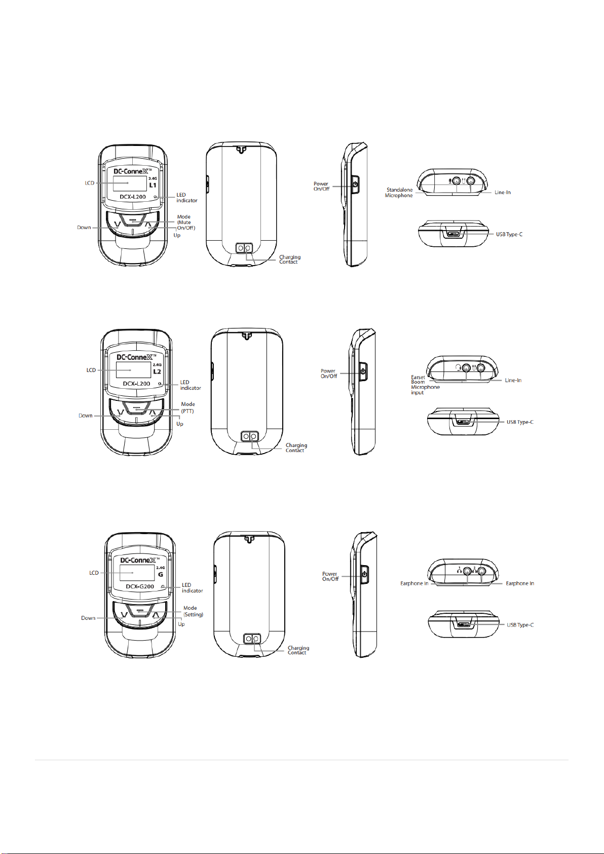
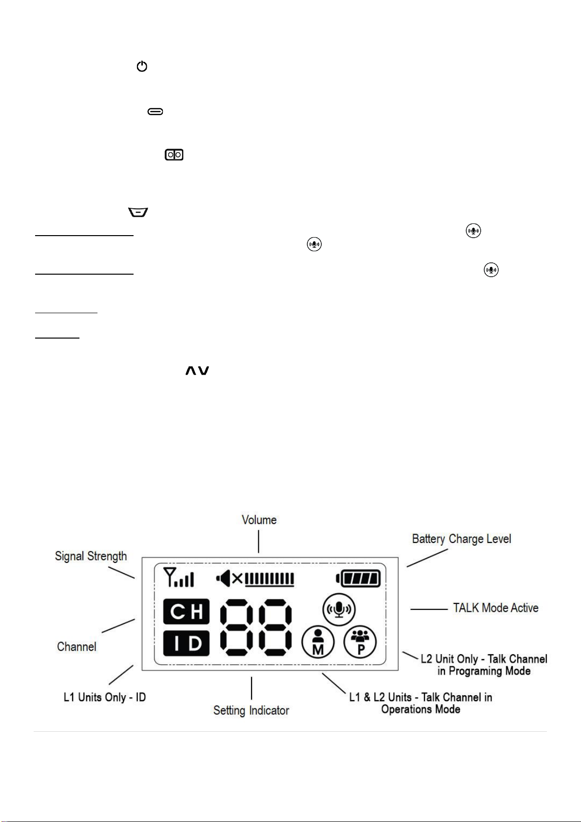
-Unit controls................................................................................................. 6
Operations ......................................................................................................................................8
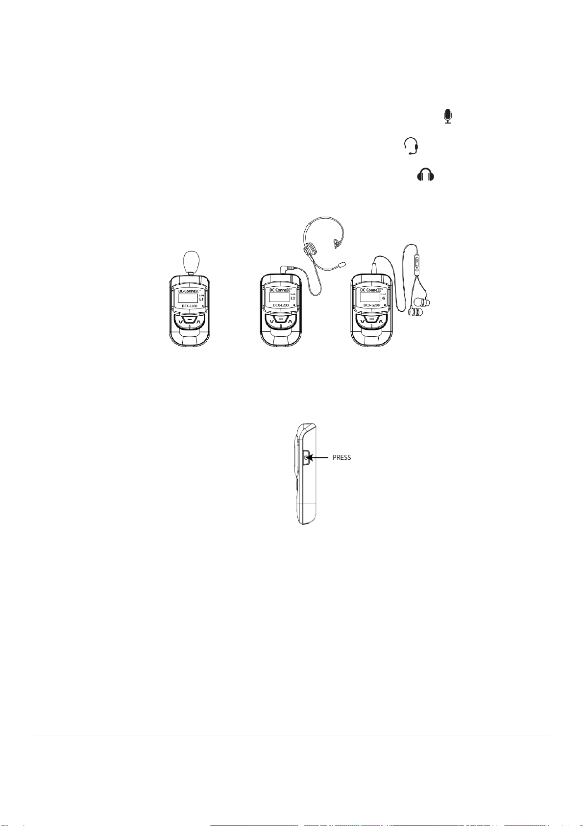
-Unpack and prepare your device for setup.................................................. 8
-Set-up ........................................................................................................ 10
-Mode & Mute On/Off.................................................................................. 11
-Audio Alerts ............................................................................................... 12
-Power On/Off............................................................................................. 12
-Detail Set-Up Instructions for Case 1, Case 2, and Case 3 Applications... 12
-Settings and Functions.............................................................................. 13
-Volume Adjustment.................................................................................... 13
-Channel & ID Selection.............................................................................. 14
-Sidetone Level Selection (L1 & L2 only).................................................... 15
-Microphone (Mic) Gain Level Selection (L1 & L2 only).............................. 16
-Line-In on DCX-L200, L210....................................................................... 17
-Charging.................................................................................................... 17
Specifications...............................................................................................................................18
Trouble Shooting Guide ..............................................................................................................19
Safety Warnings & Recycling Instructions ................................................................................20
-General...................................................................................................... 20
-Cleaning .................................................................................................... 21
-Battery....................................................................................................... 21
-Hearing Safety........................................................................................... 21
-Recycling Instructions................................................................................ 21
Compliance Notices.....................................................................................................................22
LIMITED WARRANTY...................................................................................................................22
Addendum 1 - Accessory Details & Ordering Guide ................................................................24

3 | P a g e
Introduction
DC-ConneX™ Translate Tour creates the most inclusive group experience across multiple
languages and social distances. Connect 2 Leaders to a single group or 1 Leader and 2
Translators to 3 different groups. This solution is ideal for translators or multilingual tours (up to 3
languages).
Translate Tour units are ultra-compact and lightweight with advanced digital technology. The
simple design provides easy operation with high-quality performance and functionality. A
rechargeable lithium-ion battery offers up to 9 operating hours on leader units and up to 14
operating hours on guest units.
Leader and guest units are designed to work in specific frequency ranges of 900MHz (US/CA
only), 863MHz (EU only), and 2.4GHz (Global). The US/CA & EU frequencies are dedicated audio
communications bands that provide for far less chance of interference compared with 2.4GHz
frequencies which share that frequency with Bluetooth®, Wi-Fi® and other devices that can
interfere with each other.
Key Features
Always on display
Crystal clear audio transmission with very low latency
US/CA & EU audio frequencies with less chance of interference
Flexible operation allows 2 Leaders to connect to a single group or 1 Leader and 2
Translators to connect to 3 individual groups
Each Guest unit supports 2 earphones for shared listening if desired
Accommodates up to 52 different groups of an unlimited number of users in a shared
space
Connects across distances of up to 150 meters (approx. 500 feet)
Sidetone for natural sounding speech and confirmation of connection
Audio alert signal for lost signal and low battery
Continuous operation up to 9 hours (Leader units) or 14 hours (Guest units)
Removable / replaceable Li-Ion battery
Auxiliary line-in audio on the Leader units that then broadcast background music or
other audio to the group

4 | P a g e
In the Box
Translate
Tour
Models
For
Leader
DCX-L201,11
[US/CA]
DCX-L202,12 [EU]
DCX-L203,13
For
Guests
DCX-G201,11
[US/CA]
DCX-G202,12 [EU]
DCX-G203,13
20 Unit Kit with
Case
DCX-K1D01 [US/CA]
DCX-K1D02 [EU]
DCX-K1D03
Unit &
Battery
Single Ear
Headset
w/ Boom Mic
Earphone w/
Inline
Microphone
USB-C
Charging
Cable
Lanyard
Quick Start
Guide
20-unit
Storage and
Charging
Case
Model
Indicator
Dark Gray
Light Gray
2 Dark Gray
(L1,L2)
18 Light Gray (G)
Note: 900MHz and 2.4GHz kits (DCX-K1D01, DCX-K1D02, DCX-K1D03) and the individual storage and charging
case (DCX-CBM-20) include a standard US/CA polarized plug plus an adapter for the EU/UK. The 863MHz kit
includes an EU style plug with UK adapter. The power supply and the adapters support 110-240V 50-60Hz.

5 | P a g e
Optional Accessories
Microphone
DCX-PM-01
Standalone Microphone
Headphone / Earphone / Audio
DCX-HSBM-01
Single Ear Headset with Boom Mic
DCX-HS-01
Single Ear Headset (No Microphone)
DCX-ERIM-01
Earphone w/ Inline Microphone
(for L2 units)
DCX-ER-01
Earphone (No Microphone)
DCX-LC-01
Auxiliary Line-In Cable for Accessories
Charging
DCX-UC-1
USB Charging Cable
DCX-BAT-11
Spare/Replacement Battery
DCX-CS-02
2 Bay Charger
DCX-CBM-20
20 Unit Charger & Case
Storage
DCX-BC-01
Belt Clip
DCX-CB-48
Carry Bag 48 Units
DCX-CBM-20
20 Unit Charger & Case

6 | P a g e
Unit Controls
DCX-L200 (Leader 1, L1)
DCX-L210 (Leader 2, L2)
DCX-G200 (Guest)

7 | P a g e
POWER BUTTON
Long press the Power button to turn the unit On/Off.
USB CONNECTION
USB-C port for battery charging. Units will be usable when charging via USB port.
CHARGING CONTACT
Contact points for battery charging in the optional charging stand or case.
Units will not be usable when charging in stand or case.
MODE BUTTON
Leader1 (L1) units: Long press to Mute On/Off. TALK is indicated when Talk icon appears on
LCD screen. The unit is MUTED when the Talk icon disappears.
Leader2 (L2) units: Press and hold to talk (Push to Talk (PTT) function). The Talk icon will
appear while in PTT mode.
Guest units: No action.
All units: press MODE button in SETTING mode to move to next SETTING option.
UP AND DOWN BUTTONS
Press up button to Increase or down button to Decrease volume. Long press both up and down
buttons to access SETTING options. Press up button to increment or down button to decrement a
setting choice in SETTING mode.
LCD
Displays current status and settings, always on.
LCD Display Indicators

8 | P a g e
Operations
The Translate Tour solution can support two channels of communication simultaneously. This
feature can be used to support numerous multi-speaker and multi-group applications. The
illustration below shows 3 typical use cases. Case 1 is the simplest where 1 or 2 leaders use L1
units to speak simultaneously to a single group. Case 2 and Case 3 use L1 and / or L2 units to
support multiple groups with multiple speakers. Refer to the Detail Set-up Instructions for Case
1, Case 2, and Case 3 section in this User’s Manual for settings specific to L1, L2, and G units for
proper setting selections.
Unpack and Prepare Your Device for Set-up
Your unit was shipped with a removable piece of plastic in the battery pack. Remove this plastic
piece prior to charging or using your units. If the plastic tears, remove the back cover and battery
to access and discard the piece of plastic. Replace the battery and cover.

9 | P a g e
Remove the protective film over the LCD display as shown.
Install the Included Lanyard (optional)
First remove the battery cover. Then, follow the pictorial guide below to attach the lanyard.

10 | P a g e
Set-up
STEP 1: Plug the Headset or Earphone into the units
DCX-L200 L1: Plug the microphone into the unit where the microphone icon appears.
DCX-L200 L2: Plug the headset into the unit where the headset icon appears.
DCX-G100 G: Plug the earphone into the unit where the earphone icon appears
(there are two, use either or both for two people sharing one unit).
STEP 2: Turn On
Long press the power button and adjust the volume to the level you desire.
L1 – Leader 1 and Guest use as in Case 1
The single group Translate Tour system is now ready to use with up to two leaders and unlimited
Guests! Each L1 Unit requires a unique ID number if two L1 units are used.
L2 – Leader 2
L2 Units are not used in the Case 1 application. For use of L2 in Case 2 and Case 3 applications
see the section entitled “Detail Set-up Instructions for Case 1, Case 2, and Case 3 Applications”.

11 | P a g e
Recommendations for use:
- Fully charge each unit prior to use.
- The earphones have an inline microphone and volume
control. Set the earphone volume at the highest level
(move slide forward to the + symbol). Adjust volume to a
comfortable level on Leader 2 (L2) or Guest (G) units.
- The factory ships all units with Channel (CH) number set
at “00”. Check the Channel (CH) number on all Leader
and Guest units to confirm all units have the appropriate
CH number set.
- The units must be powered off manually. There is no
automatic shut off.
- Do not run the unit battery to empty as this degrades the
life of the battery.
Mode & Mute On/Off
DCX-L200 L1 (Leader 1)
L1 is a talk-only unit that uses a single channel to transmit. In
normal operation, the L1 unit is un-muted. This is indicated by
the talk icon on the display.
- Long press the Mode button to enable mute. The
Talk icon will disappear from the display indicating the
unit is muted.
- The number displayed indicates the Channel that
the unit is transmitting on.
DCX-L200 L2 (Leader 2 or Translator for example)
L2 is a talk and listen unit that uses a different channel for talk and listen. L2 does not have a
mute on/off function but rather uses a press and hold of the Mode button to change the
channel selection from receive to transmit when talking.
- When the Mode button is pressed the transmit channel will be displayed along with
the Talk and icons, and sidetone will be heard.
- The number displayed indicates the Channel that the unit is transmitting on.
DCX-G200 (Guest)
The Translate G is a listen-only unit that uses a single channel to receive audio. Therefore, there
is no mute on/off function. The Mode button has no effect on operations.
- The number displayed indicates the Channel that the unit is receiving on.
Sidetone
Sidetone is typically a feature
found in higher end audio
communication systems and
serves two key purposes:
1. Provides real time
feedback to the
speaker on how well
they are being heard
by their audience.
2. Restores natural
sounding conversation
when noise
attenuating earphones
or headsets are used.
The audio from the
microphone is fed back into the
headset or earphone of the
speaker giving clear feedback
on quality of the audio. The
speaker will know real time if
the audio being transmitted is
poor or non-existent.
If the speaker uses a noise
attenuating headset or
earphones sidetone provides
the additional benefit of
restoring natural sounding
conversation improving the
whole tour experience.

12 | P a g e
Audio Alerts
-Low battery:
oSingle high pitch tone followed quickly by 2 lower frequency tones which recurs
every 2 minutes until the battery is recharged or has insufficient charge remaining.
oThe battery indicator will be at zero when the tone is heard. The battery should be
immediately replaced or recharged.
-Out of range or Lost Connection (Guest & L2 units):
oConnection to the Leader is established: 2 beeps will be heard. The signal bar
icon appears on the display.
oConnection to the Leader is lost: 3 beeps will be heard in quick succession. This
alert will repeat until the connection is fully lost and then stops. The signal bar icon
also disappears from the display.
oConnection can be lost or established by being out of range of the leader, the L2
Leader pressing and releasing the PTT button, or the L1 Leader powering on or off.
Power On/Off
Long press "Power" button to turn the device power On/Off.
Detail Set-up Instructions for Case 1, Case 2, and Case 3 Applications
Review Settings and Functions section of this User Manual prior to actual set-up of the units.
The Translate Tour system supports simultaneous two channel operation that enables multi-speaker
and multi-group applications. It is important to understand what each type of unit can do.
- L1 units transmit audio on a single channel and do not receive audio.
- L2 units are able to receive audio on one channel and transmit on a different channel.
- Guest units receive audio on a single channel and do not transmit audio.
In setting up the Units, it is important to pair the different units correctly via the channel selection on
each unit. This requires that you understand that the meaning of the Master icon for the L2 units
in normal mode and settings mode is different.
- L1: The Master icon indicates that the L1 unit is the audio transmitter for the
indicated.
- L2: In normal operation, the Master icon indicates the audio transmit Channel for
L2 (same as L1). However in Settings mode, the Master icon is associated with the audio
receive Channel . The Participant icon is associated with the transmit Channel .
- Guest: There is no Master or Participant icon. The Channel for audio receive appears
on the display.

13 | P a g e
Note: Two speakers may concurrently speak to a single group using L1 units (Case 1) on a single
Channel . In this case each L1 unit must have a unique ID. The ID may be changed under
Settings (L1 units only).
Settings and Functions
There are 2 modes of operation; normal mode and setting mode. The default mode is normal after
powering the unit on.
To enter Setting Mode Long press buttons together.
Quick press the Mode button to increment through the Setting options.
Setting options in the program sequence are different for each type of unit (L1, L2, G).
-Use the or buttons to increment or decrement the selection at each setting.
-Long press the buttons together to save the settings and return to normal mode
after all Settings have been changed.
Note: For L1 units, sidetone is applicable only if an optional headset or earphone is used instead
of the included standalone microphone.
Volume Adjustment
The volume level is indicated on the top middle of the display.
-In normal mode you adjust the volume to the desired level by Quick pressing the or
button on the front of the device.
-Volume can be set from 0 to 10 in increments of 2 bars.

14 | P a g e
Channel & ID Selection
Channel and ID are set as shown in the case examples shown below.
If two or more groups are operating with the same Channel number in the same geographical area
there will be interference between the groups. To avoid interference different groups operating in
the same area should use different Channel numbers.
NOTE: For 863MHz units (DCX-L202, DCX-L212, DCX-G202, DCX-K2D02), Case 2 and Case 3
uses are recommended to maintain two channels that are set 3 numbers apart. For example, use
CH=00 and CH=03, not CH=01. Otherwise, audio to the Guest units may be unclear or
missing.
-Follow the below steps to easily change Channel number on any Translate Tour device:
oPower on the unit.
oLong press of the buttons together to enter the Setting mode. The indicator
on the display blinks to confirm Setting mode has been accessed.
oQuick press the or buttons on the front of the device to set the desired Channel.
oChannel programming for specific Translate units (L1, L2, or G):
L1: Quick press the mode button to increment to ID. Quick press the or
buttons on the front of the device to set the desired ID.

15 | P a g e
You may save changes and exit the setting mode with a Long press of the
buttons together. Your changes will be saved.
L2: The first Channel is for the Master . This is the audio receive
channel.
Quick press the or buttons on the front of the device to set the
desired number for Master .
Quick press the mode button to increment to the Participant
Channel , which is the audio transmit channel.
Quick press the or buttons on the front of the device to set the
desired number.
Save changes and exit the setting mode with a long press of the
buttons together. Your changes will be saved.
G: Quick press the or buttons on the front of the device to set the desired
ID.
Save changes and exit the setting mode with a long press of the
buttons together. Your changes will be saved.
-The number of channels supported is limited by the radio frequency of the device used
according to the following:
DCX-L101/DCX-G101: 00 to 52
DCX-L102/DCX-G102: 00 to 08
DCX-L103/DCX-G103: 00 to 40
Sidetone Level Selection (L1 & L2 only)
Sidetone level (loudness) can be adjusted from 1 to 5 independent of the volume control.
Normally it is not necessary to change from the factory default setting. To make changes:
-Turn on the power of the device.
-Enter Setting mode with a Long press of the buttons together. The unit enters
SETTING mode and the indicator on the display blinks.
-Quick press Mode button to move to the Sidetone setting.
-Change the Sidetone level from 0 (S0 - off) to 5 (S5 - loudest) by quick pressing the or
buttons.

16 | P a g e
* DCX-L200, L210 (L1 and L2 Leaders)
You may save changes and exit the setting mode with a long press of the
buttons together. Your changes will be saved.
Microphone (Mic) Gain Level Selection (L1 & L2 only)
Mic gain (loudness) level can be adjusted from 1 to 8 independent of the volume control. This
setting can be helpful to normalize the loudness of the Leader if, for example, they tend to talk
very softly or loudly. Normally it is not necessary to change from the factory default setting. To
change the Mic Gain:
-Turn on the power of the device.
-Enter Setting mode with a Long press of the buttons together. The unit enters
SETTING mode and the indicator on the display blinks.
-Quick press Mode button until you are to the Mic gain setting.
-Adjust the MIC gain setting by pressing or buttons.
-MIC gain level can be set from 1 to 8 (loudest).
* DCX-L200, L210 (Leaders)
You may save changes and exit the setting mode with a long press of the
buttons together. Your changes will be saved.

17 | P a g e
Line-in on DCX-L200 (L1), L210 (L2)
The Translate Tour provides the ability to provide background sound to the Tour Guide operation.
This can be music or any audio file. Commonly this is an MP3 or similar audio file played from a
phone or dedicated music player.
-Connect the optional auxiliary line-in cable (DCX-LC-01) between the Leader Line-in input
and an external audio source as shown. Use the external audio source to set the
desired volume.
Note: The auxiliary line-in cable (DCX-LC-01) uses the CTIA TRRS standard wiring
which is the most common standard in the market. To work correctly the external
device’s audio output should conform to this standard.
Charging
The Leader and Guest units may be charged via a USB-C or via charging stations or cases via
direct connect.
-Charging is indicated by a solid Red color LED on the lower right side of the display area.
The LED turns off when charging is complete, unless the unit remains on (possible with
USB charging).
-A rapid blinking Red LED indicates a charging failure. This is most often caused by a poor
connection from the battery to the unit (remove cover and check) or the USB charging
source not suppling sufficient power to the unit (try another charger).
-Devices charged via the USB cable will continue to operate during the charging operation.
Charging will not happen as quickly as when the unit is powered down.
-Devices charged via direct connect through the case or charging stand will not operate,
turning off automatically when the device is connected to the charging case or stand if not
already turned off.

18 | P a g e
Specifications
Units
Model
Specification
DCX-L201
DCX-L211
DCX-G201
DCX-L202
DCX-L212
DCX-G102
DCX-L203
DCX-L213
DCX-G203
Radio Frequency
MHZ
902-928
863-865
2403-2480
Type: GFSK Modulation
With frequency
hopping
With frequency
hopping
Tx Output Power
mW
10
10
100
Rx Sensitivity
dBm
-95
Channel spacing
KHz
500
200
500
Frequency Bandwidth
Hz
500
Data Rate
Kbps
500
Frequency response
Hz
50-8000
Voice latency
ms
(typical)
30
Distance (Line of sight)
Meter
(typical)
150
Battery Type
Li-Ion
3.7V 1100mAh
Hours of operation
Hours
(typical)
9 for Leader
14 for Guest
Charge time
Hours
(typical)
6
Display
Negative LCD
Operational temperature range
oC
-10 to 45
Storage temperature range
oC
-20 to 60
Number of simultaneous
speakers
Maximum
2
Number of simultaneous
leaders
Maximum
2 – Leader (L1) Units
1 – Leader 2 (L2) Units
Number of simultaneous guest
transmitters (PTT)
Maximum
0
Number of simultaneous
listeners
Maximum
Unlimited
Number of Channels
Maximum
52
8
40
Audio connectors
3.5mm
CTIA TRRS Standard compliant
Dimension
mm
50 x88 x 17.5
Weight
grams
65
Battery low alert
Audio
Yes
Receive signal lost alert
Audio
Yes
Antenna
Internal
Radio Certifications
FCC, CE, IC
Warranty
1 year parts and labor (90 days on accessories)
Note: 1. Specifications subject to change without notice.
2.Audio devices have been tuned to provide the optimal user experience. Other commercial off the shelf
earphones, headphones etc. may be used but are not guaranteed by DC-ConneXTM.

19 | P a g e
Trouble Shooting Guide
Problem
Cause
Solution
Power does not turn on.
Empty or low battery.
Charge or replace the battery.
Turns off after turning on.
Low battery. Display will show “Lb”
when trying to power on, but then
shutoff “OF”.
Charge or replace the battery.
Audio not heard.
Earphone or Headset not
completely connected.
Check connections are complete and
in the correct position. Connector
may have to be pushed in very firmly
to fully seat it in the unit.
Out of range of leader.
Guests will not hear anything if the
leader unit is turned off or not close
enough.
The Leader unit is not operating at
the same frequency as the Guest
or other Leader units.
Check the front display area to be
sure the units are operating on the
same frequency (2.4Ghz, 902MHz or
863MHz).
CH assigned to leader and guest is
not the same.
Set all users to the same group
number.
Obstacle between leader and
guest.
Move to another place to avoid
obstacles.
More than 1 leader in the vicinity is
in the same group.
Move away from 2nd leader or
change group assignment.
CH and or ID settings are not valid.
Confirm programming referencing
guidelines herein for Case 1, 2, or 3
as desired. Note that 863MHz units
should have at least 3 steps
difference between the L2 receive
and transmit channels selected.
Unknown cause.
Occasionally, the network connecting
Leaders and Guests will cease to
function properly. This can be
resolved by turning off all units.
Then, power on the Leader 1 (L1)
unit first. Follow this by turning on all
the Leader 2 (L2) units. Last, turn on
the Guest units.
Leader 2 units no transmit
audio (no Sidetone) but
still receiving audio.
Not pressing and holding the PTT
(Mode) button.
Be sure to fully press AND hold the
PTT button.
Audio is distorted.
Microphone gain is set too high.
Check settings on transmitting unit.
Change to lowest setting.
Connectors are not fully seated.
Check all headset & earphone
connections. Connector may have to
be pushed in very firmly to fully seat
it in the unit.
Headset or earphone is defective.
Try a different headset or earphone.

20 | P a g e
Problem
Cause
Solution
863MHz units have a very narrow
frequency band in which to operate
because of the EU/UK frequency
allocations. In some situations the
transmit and receive channels can
interfere with each other.
If using 863MHz units be sure the L2
unit receive and transmit channels
are set at least 3 steps.
Auxiliary audio does not
broadcast.
(Leader unit only)
Aux cable connection is incorrect.
Check connections. Connector may
have to be pushed in very firmly to
fully seat it in the unit.
Volume on the audio device is
muted or turned down.
Unmute or increase volume on audio
device.
Distance from Leader to
Guest is shorter than
expected.
There are obstacles between the
Leader & Guest Unit.
Move to an area where objects are
not interfering.
There is interference from other
devices operating in the same
frequency. This is unlikely with 902
or 862MHz systems. 2.4GHz
systems operate alongside
Bluetooth, Wi-Fi and other
systems.
Move to a location with fewer
phones, PCs or other active devices.
Switch to a 902MHz or 863MHz
system if you are in the US.
Unit will not shut down.
Software fault.
Remove the battery or
simultaneously press the down/up
and mode buttons.
Red charging LED
remains on for more than
the 6 hours of typical
charge time.
The battery will typically fully
charge in about 6 hours but the red
LED may remain on for a few
hours after the battery is fully
charged due to differences in
chargers and some small amount
of trickle charge that’s going on.
Battery status can be checked on the
display to confirm the charge state.
If the battery takes much longer than
6 hours to charge this is a sign the
battery may be aging and should be
replaced.
Red LED remains on
when charging.
The Red LED may remain on while
charging via the USB port and the
Unit is left on. This is because to
stay on the Unit will continue to
draw power which requires a USB
power draw.
This is normal operation.
If this happens when the unit is
powered off, this is a sign the battery
may be aging and should be
replaced.
Safety Warnings & Recycling Instructions
General
- Do not use this device or accessories in water or rain.
- Do not block any ventilation openings.
Other manuals for DCX-L201
1
This manual suits for next models
11
Table of contents