DCA M1Q-FF-85 User manual

Edition 2 July, 2011
Read through carefully and understand these
instructions before use.

GENERAL SAFETY RULES
(ForAll Tools)
WARNING! Read and understand all instructions. Failure to
follow all instructions listed below may result in electric shock, fire
and/or serious personal injury.
Work Area
1. Keep work area clean and well lit. Cluttered areas and benches invite
injuries.
2. Do not operate power tools in explosive atmospheres, such as in the
presence of flammable liquids, gases, or dust. Power tools create sparks
which may ignite the dust or fumes.
3. Keep bystanders, children, and visitors away while operating a power
tool. Distractions can cause you to lose control.
Electrical Safety
4. Power tools must be plugged into an outlet properly installed or
grounded in accordance with all codes and ordinances. Never modify
the plug in any way. Do not use any adaptor plugs with grounded
(earthed) power tools. The original plug and proper outlet may reduce the
risk of electric shock.
5. Avoid body contact with grounded surfaces such as pipes, radiators,
ranges and refrigerators. There is an increased risk of electric shock if your
body is grounded.
6. Do not expose power tools to rain or wet conditions. Water entering a
power tool will increase the risk of electric shock.
7. Do not abuse the cord. Never use the cord to carry the tools or pull the
plug from an outlet. Keep cord away from heat, oil, sharp edges or
moving parts. Replace damaged cords immediately. Damaged or entangled
cords increase the risk of electric shock.
8. When operating a power tool outside, use only extension cords intended
for outdoors use. These cords may reduce the risk of electric shock.
Personal Safety
9. Stay alert, watch what you are doing and use common sense when operating
a power tool. Do not use tool while tired or under the influence of drugs,
alcohol, or medication. A moment of inattention while operating power tools may
result in serious personal injury.
10.Dress properly. Do not wear loose clothing or jewelry. Contain long hair.
Keep your hair, clothing, and gloves away from moving parts. Loose clothes,
jewelry, or long hair can be caught in moving parts.
11.Avoid accidental starting. Be sure switch is off before plugging in. Carrying
tools with your finger on the switch or plugging in tools that have the switch on
invites accidents.
12.Remove adjusting keys or wrenches before turning the tool on. A wrench or a
key that is left attached to a rotating part of the tool may result in personal injury.
13.Do not overreach. Keep proper footing and balance at all times. Proper footing
and balance enables better control of the tool in unexpected situations.
14.Use safety equipment. Always wear eye protection. Dust mask, non-skid safety
shoes, hard hat, or hearing protection must be used for appropriate conditions.
Ordinary eye or sun glasses are NOT eye protection.
15.If devices are provided for the connection of dust extraction and collection
facilities, ensure these are connected and properly used. Use of dust collection
can reduce dust-related hazards.
Tool Use and Care
16.Do not force tool. Use the correct tool for your application. The correct tool will
do the job better and safer at the rate for which it is designed.
17.Do not use tool if switch does not turn it on or off. Any tool that cannot be
controlled with the switch is dangerous and must be repaired.
18.Disconnect the plug from the power source before making any adjustments,
changing accessories, or storing the tool. Such preventive safety measures
reduce the risk of starting the tool accidentally.
19.Store idle tools out of reach of children and other untrained persons. Tools
are dangerous in the hands of untrained users.
-1- -2-

20. Maintain tools with care. Keep cutting tools sharp and clean. Properly
maintained tools with sharp cutting edges are less likely to bind and are
easier to control.
21. Check for misalignment or binding of moving parts, breakage of parts,
and any other condition that may affect the tools operation. If damaged,
have the tool serviced before using. Many accidents are caused by poorly
maintained tools.
22. Use only accessories that are recommended by the manufacturer for
your model. Accessories that may be suitable for one tool, may become
hazardous when used on another tool.
Ser ice
23. Tool service must be performed only by qualified repair personnel.
Service or maintenance performed by unqualified personnel could result in a
risk of injury.
24. When servicing a tool, use only identical replacement parts. Follow
instructions in the Maintenance section of this manual.
Use of
unauthorized parts or failure to follow Maintenance instructions may create a
risk of electric shock or injury.
VOLTAGE WARNING:
Before connecting the tool to a power source (receptacle, outlet, etc.), be sure the
voltage supplied is the same as that specified on the nameplate of the tool. A
power source with voltage greater than that specified for the tool can result in
SERIOUS INJURY to the user, as well as damage to the tool. If in doubt, DO NOT
PLUG IN THE TOOL. Using a power source with voltage less than nameplate
rating is harmful to the motor.
SPECIFICATIONS
Rated Power Input 580 W
Strokes per Minute 500-3100 …/min
Bevel Cutting Angle (Right/Left) 0-45 °
Max. Cutting Capacities
Wood 85 mm
Aluminum 20 mm
Steel 10 mm
Net Weight 2.7 Kg
※Due to the continuing program of research and development, the specifications
herein are subject to change without prior notice.
ADDITIONAL SAFETY RULES
1. Always wear safety glasses or goggles. Ordinary eye or sun glasses are NOT
safety glasses.
2. Use only sharp blades in good condition. Replace cracked, dulled or deformed
blade immediately.
3. Hold the tool only by insulated surfaces when performing an operation where the
cutting tool may contact hidden wiring or its own cord. Contact with a “live” wire will
make exposed metal parts of the tool “live” and shock the operator.
4. Always be sure that the tool is switched OFF before plugging to avoid the risk of
injury caused by accidental starting.
5. Hold the tool firmly. Keep hands away from cutting area and blade.
6. Keep the cord away from the cutting area and position it at the rear of the tool
during the cutting operation.
7. Make sure the blade is not contacting the workpiece before switching on the tool.
8. Avoid cutting nails. Inspect workpiece for any nails and remove them before
operation.
-3- -4-

9. Remove all obstacles both on and under the cutting line of the workpiece
during operation.
10. Check for the proper clearance beyond the workpiece before cutting so that
the blade will not strike the floor, workbench etc.
11. Do not cut oversize workpiece.
12. Rest the base flat on the workpiece in cutting operation, use stable supports
or workbench when cutting small and thin workpieces.
13. Do not leave the tool running. Operate the tool only when hand-held.
14. Always switch off and wait for the blade to come to a complete stop before
removing the blade from the workpiece.
15. Do not stop the blade by lateral pressure on it.
16. Do not touch the blade or the workpiece immediately after operation; they
may be extremely hot and could burn your skin.
17. In order to avoid operational malfunctions, do not saw gypsum board etc.
from below or overhead.
18. Do not work with materials containing asbestos.
19. Be sure to use an earth-leakage circuit breaker, with actuating current not
more than 30mA and actuating time not more than 0.1s, when use this tool
outside, and use only waterproof extension cords intended for outdoors use.
20. Never allow children or untrained person to use the tool.
SAVE THESE INSTRUCTIONS.
WARNING!
MISUSE or failure to follow the safety rules stated in this
instruction manual may cause serious personal injury.
GENERAL DESCRIPTION
1.
Screwdriver Inlet Hole 8. Blade Roller Guide
2.
Trigger Switch 9. Saw Blade*
3.
Lock Button 10.
Safety Protector
4.
Hex Wrench 11.
Stroke Rod
5.
Switch for Sawdust Blower 12.
Scale for Bevel Cutting
6.
Base 13.
Hex Socket Head Screw
7.
Blade Orbit Selector Lever 14.
Protractor**
Note: *—Optional Accessory, Sold Separately; **—Commercially Available.
-5- -6-

INSTRUCTIONS FOR OPERATION
Safety Protector
CAUTION:
Always keep the safety protector in
place during operation for your
safety.
The safety protector attached to the
housing prevents unintentional contact
with the saw blade while working and
should not be removed. (Fig. 2)
Switch Action
CAUTION:
Before plugging in the tool, always check to see that the trigger switch actuates
properly and returns to the “OFF” position when released.
Switch can be locked in the “ON” position for ease of operator comfort during
extended use. Apply caution when locking tool in the “On” position and maintain
firm grasp on tool.
To start the tool, simply press the
switch trigger. Release the trigger to
stop.
For continuous operation, pull the
trigger and then push in the lock
button. To stop the tool from the
locked position, pull the trigger fully
and then release it. (Fig. 3)
Speed Control
Speed can be infinitely adjusted between
500 and 3,100 strokes per minute by
turning the adjusting dial. Higher speed is
obtained when the dial is turned clockwise;
lower speed is obtained when it is turned
counterclockwise. (Fig. 4)
Installing or Remo ing the Saw Blade
CAUTION:
Always be sure that the tool is switched OFF and unplugged before installing or
removing the saw blade.
Wear protective gloves when replacing/removing the saw blade.
Always clean out all chips or foreign matter adhering to the blade and/or blade holder.
Failure to do so may cause insufficient tightening of the blade, resulting in a serious
personal injury.
Do not touch the blade or the workpiece immediately after operation; they may be
extremely hot and could burn your skin.
Always secure the blade firmly. Insufficient tightening of the blade may cause blade
breakage or serious personal injury.
To install the saw blade, firstly set the blade orbit selector lever to
level 3.
Then finish the installment as follows:
—Insert the blade into the stroke rod crosswise to the cutting
direction.
-7- -8-

—Turn the saw blade with the teeth facing in the cutting
direction. Slightly lift the saw blade so that the back of the
saw blade comes to rest in the groove of the blade roller
guide. Allow it to engage by pulling slightly.
—Insert the provided screwdriver into
the screwdriver inlet hole and
tighten the locking screw clockwise
to finish the installment. (Fig. 5)
To remove the saw blade, follow the
installing procedure in reverse.
Sawdust Blower
The sawdust blower leads an air jet to the saw blade. The air jet keeps sawdust
from covering the cutting line during operation. The air flow can be switched on or
off with the switch for the sawdust blower.
Sawdust Blowing Level I:
Use low airstream when cutting in metals and when
coolants/ lubricants are used.
Sawdust Blowing Level II:
Use medium airstream when cutting in materials with low
chip removal rate, e. g. hardwood.
Sawdust Blowing Level III:
High airstream, for cuts in materials with high chip removal
rate, e.g. soft wood, plastic, etc.
Selecting Orbital Action
CAUTION:
Select the low orbital action setting (or switch it off) for a finer and cleaner cutting
edge.
Switch the orbital action off for cutting thin materials such as sheet metal.
Select the low orbital action when cutting hard materials such as steel.
Select high orbital action when cutting soft materials and when sawing in the
direction of the grain.
The four orbital action settings of the tool allow optimum adaptation of cutting speed,
cutting capacity and cutting pattern to the material being sawed. The orbital action can
be adjusted in four steps with the blade orbit selector lever, and it also can be adjusted
during operation.
Step 0:
No orbital action.
Step 1:
Low orbital action.
Step 2:
Medium orbital action.
Step 3:
High orbital action.
-9- -10-

Cutting/Sawing Operation
CAUTION:
Always hold the tool with the base flush with the workpiece. Failure to do so may
cause blade breakage, resulting in a serious injury.
Advance the tool very slowly when cutting curves or scrolling. Forcing the tool
may cause a slanted cutting surface and blade breakage.
For tight curves, it is best to use a narrow saw blade.
Switch on the tool without the blade making any contact with the workpiece and
wait until the blade attains full speed. Then rest the base flat on the workpiece and
gently move the tool forward along the previously marked cutting line.
Be el Cutting
CAUTION:
Always be sure that the tool is switched off and unplugged before tilting the
base.
Bevel cuts can be finished at any angle between 0°-45°(left or right) by tilting the
base.
To adjust the cutting angle, loosen the
hex socket head screw and slightly
slide the base towards the saw blade,
then the base can be tilted to a
maximum of 45°to the right or left.
Tilt the base to the desired angle and
retighten the hex socket head screw.
The cutting angle can be pre-adjusted
with the scale for bevel cutting. It is recommended to use a commercial protractor
for precise adjustment. (Fig. 6)
To achieve precise cutting angles, the base can be fitted at 0°and 45°(left and right).
For this, however, the base must be pushed back (towards the motor) to the stop so
that the notch in the base engages in the positioning pin.
For cutting angles out of 0°-45°(left and right), adjust the angle with the scale for bevel
cutting primarily and then use a set square or protractor to finish the adjustment.
When returning the base to the 0°(normal) position, lightly push the base toward the
direction of the motor until it can be felt to engage, then retighten hex socket head
screw.
Repositioning the Base
CAUTION:
With the base set back, it is only possible to work in the 0°(normal) position. The
guide rule as well as the splinter guard cannot be used in this position.
When tightening the screw, the base must be pressed to the rear until it can be felt to
engage.
For flush cuts close to edges, the base can
be moved to the rear for easy operation.
Use a hex wrench to remove the screw,
take off the base and move it to the rear so
that the screw can be screwed into the rear
thread, and then tighten the screw to
secure the base. (Fig. 7)
Splinter Guard
CAUTION:
The splinter guard cannot be used for certain types of saw blades (e. g., set saw
blades).
The splinter guard cannot be used when making bevel cuts.
-11- -12-
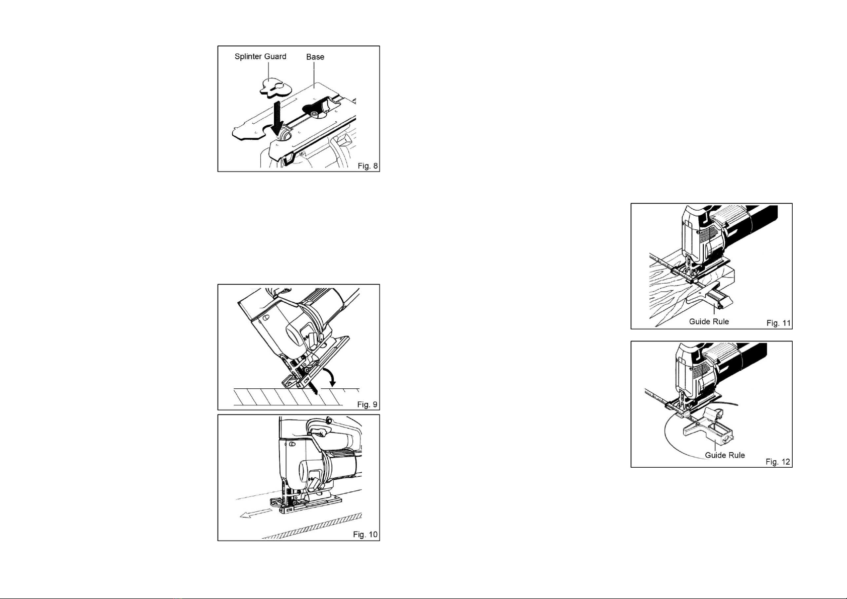
For splinter-free cuts, the splinter
guard can be used.
To install the splinter guard, simply
press it into the base. (Fig. 8)
Plunge Cutting
CAUTION:
Apply plunge cutting only when working on soft materials, such as wood,
aerated concrete, gypsum plaster boards, etc.!
Use only short saw blade for plunge cutting.
Pull out the saw blade only until it
comes to a complete stop to avoid
kickback when make a plunge cut.
Place the tool with the front edge of
the base onto the workpiece and
switch on. Firmly hold the tool against
the workpiece while tilting the tool and
slowly plunge the saw blade into the
workpiece. (Fig. 9)
When the base fully lays on the
surface, continue sawing along the
cutting line. (Fig. 10)
Metal Cutting
Always use a suitable coolant (cutting oil) when cutting metal or similar materials.
Failure to do so will cause significant blade wear.
Guide Rule (optional accessory)
CAUTION:
Always be sure that the tool is switched off and unplugged before installing or
removing accessories.
The combined circle cutter/parallel guide
rule enables repeatedly cuts in a certain
width conveniently.
To install the guide rule, insert it into the
rectangular hole on the side of the base.
Slide the guide rule to the desired cutting
width position. (Fig. 11)
Certain radius circular cutouts can be
made conveniently and repeatedly by
using the combined circle cutter/parallel
guide rule. (Fig. 12)
With the combined circle cutter/parallel
guide rule parallel cuts or circular cutouts in
materials of up to 30 mm thickness can be
made.
-13- -14-

MAINTENANCE AND INSPECTION
CAUTION:
Always be sure that the tool is switched off and unplugged before attempting to
perform inspection or maintenance.
1.
After Metal Cutting
When cutting metals under extreme working conditions, conductive dust can
accumulate in the interior of the machine and impair its protective insulation.
In such cases, it is recommended to use stationary dust extraction equipment,
to blow out the ventilation slots frequently and to power the tool via a ground
fault circuit interrupter.
2.
Inspecting the Mounting Screws
Regularly inspect all mounting screws and ensure that they are properly
tightened. Should any of the screws be loose, retighten them immediately.
Failure to do so could result in serious hazard.
3.
Maintenance of the Motor
The motor unit winding is the very “heart” of the power tool. Exercise due care
to ensure the winding does not become damaged and /or wet with oil or water.
Always keep the power tool and its ventilation slots clean.
4.
Inspecting of the Blade Roller Guide
The blade roller guide should occasionally be checked for wear and lubricated
with a drop of oil. If it is worn, it must be replaced.
5.
Inspecting and Replacing Carbon Brushes
Remove and check the carbon brushes regularly. Replace when they wear
down to the limit mark. Keep the carbon brushes clean and free to slip in the
holders. Both carbon brushes should be replaced at the same time and use
only identical carbon brushes.
※
※※
※To maintain product SAFETY and RELIABILITY, repairs, any other maintenance
or adjustment should be performed by authorized centers, always using original
replacement parts.
-15- -16-

EXPLAINATION OF GENERAL VIEW
1 Handle Cover 26
Snap Washer
2 Pan Head Tapping Screw
ST4.2×19 27
Washer
3 Nut 28
Pan Head Screw M4×14
4 Pan Head Screw M4×20 (with
Spring and Flat Washers) 29
Needle Bearing HK0608
5 Pan Head Tapping Screw
ST4.2×16 (with Flat Washer)
30
Pin
6 Strain Relief 31
Eccentric Block
7 Cord Guard 32
Sleeve
8 Cord 33
Balance Block
9 Hex Wrench 34
Washer
10
Nameplate 35
Washer
11
Rear Cover 36
Grip Ring
12
Pan Head Tapping Screw
ST4.2×19 37
Washer
13
Capacitor 38
Washer
14
Pan Head Tapping Screw
ST2.9×10 39
Shifter
15
Coil Spring 40
Washer
16
Carbon Brush Holder 41
Eccentric Gear
17
Carbon Brush 42
Needle Bearing TN1
18
Trigger Switch 43
Washer
19
Pan Head Screw M5×25 (with
Spring and Flat Washers) 44
Washer
20
Handle 45
Snap Washer
21
Motor Housing 46
Blower Spigot
22
Pan Head Tapping Screw
ST3.5×9 47
Pan Head Tapping Screw
ST4.2×25
23
Baffle Plate 48
Washer
24
Stator 49
Gear Housing
25
Seal Pad 50
Blade Orbit Selector Lever
EXPLAINATION OF GENERAL VIEW
51
Spring 77
Stroke Rod
52
Retaining Sleeve 78
Slide Support
53
Switch for Sawdust Blower 79
Slide Groove
54
Grip Ring 80
Cross Recessed Countersunk
Head Screw M3.5×10
55
Sleeve 81
Pan Head Screw M4×8 (with
Flat Washer)
56
Felt Washer 82
Positioning Pin
57
Seal Cover 83
Pan Head Screw M4×14
58
Ball Bearing 609SS 84
Guide Plate
59
Circlip for Hole 85
Spring
60
Armature Assembly 86
Pad
61
Ball Bearing 627ZZZC 87
Shim
62
Saddle Washer 88
Pin
63
Washer 89
Gear Housing Cover
64
Bracket 90
Pan Head Screw M4×14
65
Hex Nut 91
Safety Protector
66
Aluminium Base 92
Guide Roller Retainer
67
Inner Base 93
Snap Washer
68
Cross Recessed Countersunk
Head Screw M5×8 94
Shaft
69
Clamp Plate 95
Washer
70
Hex Socket Head Screw M6×16 96
Needle Bearing SCE
71
Lock Screw M6×12 97
Guide Roller
72
Oil-Retaining Bearing 98
Inductance
73
Oil-Retaining Bearing 99
Label
74
Washer 100
Long Wire
75
Shaft Cover 101
Middle Wire
76
Washer 102
Short Wire
-17- -18-
Table of contents


