DCI DigiTrak FALCON F5 Sub-k Rebar Owner's manual

DIGITALCONTROLINCORPORATED
ii Supplement B for DigiTrak®Falcon F5®
403-1840-00-A, printed on 10/4/2017
© 2017 by Digital Control Incorporated. All rights reserved.
Trademarks
The DCI®logo, DigiTrak®, DigiTrak Falcon®, and Falcon F5®, are U.S. registered trademarks.
Patents
Patent pending.
Limited Warranty
All products manufactured and sold by Digital Control Incorporated (DCI) are subject to the terms of a Limited Warranty. A copy of the
Limited Warranty can also be obtained at www.DigiTrak.com.
Important Notice
All statements, technical information, and recommendations related to DCI products are based on information believed to be reliable.
However, DCI does not warrant or guarantee the accuracy or completeness of such information. Before using any DCI product, the
user should determine the suitability of the product for its intended use. All statements herein refer to DCI products as delivered by DCI
for use with horizontal directional drilling in the ordinary course, and do not apply to any user customizations, third-party products, or
any usage of the DCI product outside of the ordinary course. Nothing herein shall constitute a warranty by DCI nor will anything herein
be deemed to modify the terms of DCI’s existing Limited Warranty applicable to all DCI products. DCI may update or correct the
information in this manual from time to time. You may find the most recent version of this manual on DCI's website, www.DigiTrak.com.
Under Service & Support, click Documentation and select from the Manuals drop-down menu.
Watch our DigiTrak Training Videos at www.YouTube.com/DCIKent

DIGITALCONTROLINCORPORATED
Supplement B for DigiTrak®Falcon F5®iii
Table of Contents
Important Safety Instructions 1
What is This Document For? 1
Other Documents 1
What's New 1
Frequency Optimizer (FO) 2
Selecting Sub-k™ Rebar 3
Switching Bands 4
Optimizing with Sub-k™ Rebar 5
Full Scale Sensitive Pitch (FSSP) 6
Surface Grade 7
Compatible Transmitters 8
Transmitter Current Draw Warning 8
Changing Frequency Bands 8
Updates to Manual 9
Getting Started 9
Setup Summary 9
Receiver 9
Overview 9
DataLog 10
Left/Right Offset 10
Flags and Pins 10
Calibration and AGR 10
View Calibration 10
Transmitter Selection and Frequency Optimization 10
Frequency Optimization 10
View Frequency Optimization 10
Diagnostics 11
Locating Screens 11
Depth Screen, Max Mode 11
Transmitter 11
Batteries and Power On/Off 11
Sleep Mode 11
Attenuated Signal 11
Transmitter Drill Head Requirements 12

DIGITALCONTROLINCORPORATED
iv Supplement B for DigiTrak®Falcon F5®

DIGITALCONTROLINCORPORATED
Supplement B for DigiTrak®Falcon F5®1
Important Safety Instructions
Always operate your DigiTrak locating system properly to obtain accurate depth, pitch, roll, and locate
points. If you have any questions about the operation of the system, please contact DCI Customer Service
for assistance.
This document is a companion to your Falcon F5®guidance system operator's manual, which contains a
more thorough list of warnings regarding the potential for serious injury and death, work slowdowns, property
damage, and other hazards and warnings regarding the operation of horizontal drilling equipment. Please read
and understand your system operator's manual completely before operating the equipment described in this
manual.
What is This Document For?
Supplement B addresses the changes to the user interface that accompany the introduction of the Falcon F5
Sub-k™ Rebar transmitter and Full Scale Sensitive Pitch (FSSP). If you purchased your Falcon F5 guidance
system without this capability, you can contact Customer Service for details on obtaining an update that
includes these features. This supplement discusses the user interface changes that accompany these
features.
Other Documents
Please visit the Falcon F5 manuals page at our website to download the:
lFalcon F5 Operator's Manual
lFalcon F5 Supplement A: iGPS
What's New
The latest Falcon F5®guidance systems include an updated frequency optimizer and other productivity-
enhancing features.
lThe Sub-k™ Rebar (FTR) transmitter in its Down mode uses mid-power, ultra-low frequencies in the
0.33–0.75kHz range for the depth/locate signal, plus frequencies at 4.5–18 kHz specifically for data, for
best performance around passive interference like rebar. It also features a standard-power Up mode that
functions like our original transmitter using just Bands 7–16 (4.5–18 kHz). The Sub-k Rebar transmitter is
an excellent solution for tough interference conditions commonly found around rebar.
lFull Scale Sensitive Pitch provides extremely sensitive 0.1% pitch resolution throughout the entire
range of ±99.9% slope for precision grade work.
lThe frequency optimizer now always shows interference in the two currently selected bands as active
graphs at the left of the FO screen. This also simplifies the Transmitter Selection menu by removing the
now unneeded View Frequency Optimization icon.
To add these features to an earlier-model Falcon F5 receiver, contact Customer Service at 425.251.0559 or
dci@digital-control.com.
Rebar transmitter users in Australia may require a modification to the receiver to accommodate regional
frequency parameters. Please contact your local dealer for more information.

DIGITALCONTROLINCORPORATED
2 Supplement B for DigiTrak®Falcon F5®
Frequency Optimizer (FO)
The frequency optimizer now shows active interference in the two currently optimized bands as live graphs
at the left of the FO screen. If you walk the intended bore path with the transmitter off and these levels remain
low, the current bands may be performing well enough that you may choose to not scan and pair new
frequency bands.
1. Interference in the currently
optimized bands
2. Start frequency optimizer
3. Accept selected bands
4. Exit
Frequency Optimizer
This removes the View Frequency Optimization option from the Transmitter Selection menu (#2below).
1. Frequency optimization
2. View Frequency Optimization
option is removed
Transmitter Selection Screen
Simply select Frequency optimization to view current levels of active interference in the current bands.

DIGITALCONTROLINCORPORATED
Supplement B for DigiTrak®Falcon F5®3
Selecting Sub-k™Rebar
On a Sub-k™ Rebar (FTR) transmitter, the receiver uses six frequency bands specifically intended for use in
areas of high passive interference:
Depth Bands Data Bands
Band Number 0.3 0.5 0.7 7 11 16
Range in kHz 0.33 – 0.40 0.40 –0.58 0.58 – 0.75 4.5 – 9.0 9.0 – 13.5 13.5 – 18
The Sub-k Up band provides standard-power depth/data capability with options for Bands 7, 11, and 16. The
mid-power Down band uses these same frequencies for data, but assigns depth to new ultra-low bands 0.3,
0.5, and0.7. By focusing performance in a narrower band of low frequencies, the Sub-k Rebar transmitter
achieves exceptional results around sources of passive interference such as rebar.
With Sub-k, optimize and assign the Up and Down band in the same location, since they use the same band
for data.
To select the Sub-k Rebar (FTR) transmitter:
1. From the Main menu, select Transmitter selection ,Transmitter selection , then the
new FTR Sub-k transmitter (for 19", 15", or 8").
Transmitter Selection
2. At the Locate screen, toggle down to open the Main menu to optimize, pair, and calibrate the
transmitter.
The Up and Down bands on a Sub-k Rebartransmitter have different performance
characteristics, most notably, range. Using the 15" transmitter as an example, its depth/data
range using the ultra-low frequencies available in the Down band is 50ft. However, when
using the Up band and only its higher 4.5–18 kHz frequencies, its range is about 30% farther,
or65ft.

DIGITALCONTROLINCORPORATED
4 Supplement B for DigiTrak®Falcon F5®
Switching Bands
Switch the transmitter between Up and Down bands pre- or mid-bore using any of the methods described in
the Falcon F5 QSG or operator's manual.
On the receiver, hold-toggle right at the Locate screen to open the Band Selection Menu, where you can
switch between the optimized Up and Down bands and turn on fluid pressure monitoring.
lThe Up band is standard power with three bands encompassing a range of low frequencies.
lThe Down band is mid-power with three ultra-low bands (0.3, 0.5, and 0.7) specifically for depth/locates,
plus also uses the optimized Up band (7, 11, or 16) for data signal.
1. Up or Down band
2. Pressure on/off
3. Locate mode
Band Selection Menu
Select Pressure to show fluid pressure transmitter data.
The FO graph does not show passive interference. The lowest band in the ultra-low frequency
range (0.3) is always best for passive interference alone. However, if active interference in
that band (shown on the FO graph) is exceptionally high, consider using 0.5 or0.7.

DIGITALCONTROLINCORPORATED
Supplement B for DigiTrak®Falcon F5®5
Optimizing with Sub-k™Rebar
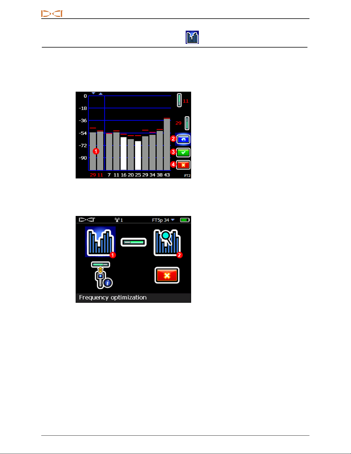
The frequency optimizer (FO) has a slightly different look when you use a Sub-k™ Rebar transmitter. In
addition to the currently optimized FObars at the left, the remaining bars show the active interference (noise)
in just six low-frequency bands.
1. Up mode band (one)
2. Down mode bands (two)
3. Interference in data bands 7–16
4. Interference in depth bands 0.3–0.7
5. Current transmitter
FOScreen for Rebar Transmitter
Here's how to optimize with a Sub-k transmitter:
1. From the Main menu, select Transmitter Selection , then Frequency Optimization .
2. With the transmitter off, walk the bore while observing interference levels in the two currently
optimized bands (left side of screen). Interference will be greatest where two bars are highest, and
recorded by the red Maximum marks.
3. At the point of greatest interference, select Scan to optimize frequencies in the three data and
three depth bands. If the current optimized bands are already performing as well as these newly
optimized bands and you want to continue using them, select Exit and skip to the last step.
4. Toggle to a wide band (7, 11, or 16) and click twice to select and assign as the Up band. The band
number changes from red to green to indicate a new selection.
The lowest band in the ultra-low
frequency range (0.3) is always
best for passive interference
alone. However, if active
interference in that band (shown
on the FO graph) is high compared
to the other bands, consider using
0.5 or0.7.
5. Toggle to a narrow depth band (0.3, 0.5, or 0.7) and click twice to
select and assign as the Down band. This ultra-low frequency band
is for depth/locate signal; data signal is sent on the Up band
frequency. The two bands used in Down mode, such as 16 and 0.3,
display together above as 16.3.
6. Insert batteries to power on the Sub-k transmitter, which will cause
interference levels on the graph to spike and confirm that the
transmitter is on. If the levels do not change, the transmitter is not
powered on.
7. Select OK to assign the bands.
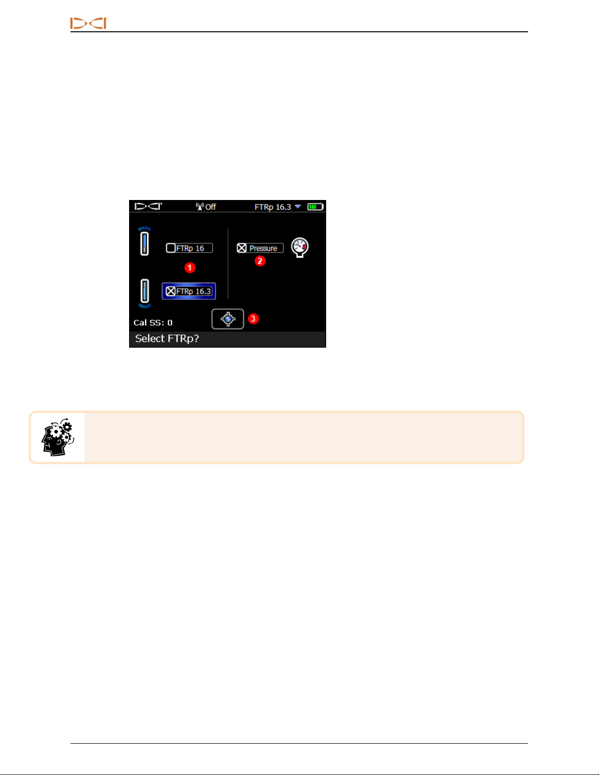
8. At the next screen, select Transmitter pairing request to pair with the transmitter.
9. At the transmitter pairing request screen, select whether to pair in standard pitch mode or Full Scale
Sensitive Pitch (FSSP) mode (FSSP requires an FSSP-capable transmitter; see page6).

DIGITALCONTROLINCORPORATED
6 Supplement B for DigiTrak®Falcon F5®
10. Pair the transmitter by aligning the IR ports (the divot on the transmitter and the small round port in
the upper center portion of the receiver front) and clicking the trigger.
11. After pairing, the transmitter defaults to using the Down band. Calibrate with the transmitter in a
housing in both the Up and Down bands, then perform an AGR test as described in the Falcon F5
operator's manual.
Full Scale Sensitive Pitch (FSSP)
FSSP mode requires an FSSP-capable transmitter. FSSP provides 0.1% pitch resolution throughout the
entire range of ±99.9% slope for precision grade work.
FSSP is included on Falcon F5 19" and 15" fluid pressure transmitters with software v2.1.1.0 or
higher. You can view a transmitter's software version by selecting Transmitter selection
from the Main menu, then Transmitter information , then Transmitter information
request while holding the IRport to the receiver as if you were pairing. If you select FSSP
mode while pairing but it is not available on the transmitter, the transmitter will pair but only
provide the standard pitch resolution.
After the transmitter pairing request screen, select Transmitter pairing request 0.1%/100% (#2 below).
1. Standard pitch mode
2. FSSP mode
Transmitter Pairing Request Screen
Standard transmitter pairing (#1 above)yields lower pitch resolution as the pitch increases:
±% Grade ± Degrees Grade % Resolution
0 – 3% 0 – 1.7° 0.1%
3 – 9% 1.7 – 5.1° 0.2%
9 – 30% 5.1 – 16.7° 0.5%
30 – 50% 16.7 – 26.6° 2.0%
50 – 90% 26.6 – 42.0° 5.0%
But in FSSP mode, the FTP transmitter retains and transmits 0.1% resolution at all times within ±99.9%
slope.

DIGITALCONTROLINCORPORATED
Supplement B for DigiTrak®Falcon F5®7
While in FSSP mode, fluid pressure resolution decreases:
psi 25 50 75 100 125 150 175 200 225 250
Standard Resolution
0 – 75 1 psi
75 – 250 5 psi
FSSPResolution
0 – 50 5 psi
50 – 150 10 psi
150 – 250 20 psi
Surface Grade
Surface grade assists in determining the pitch of the surface terrain being drilled, which is useful when it is
necessary to maintain a consistent drilling depth. To show surface grade, open the Main menu and select
Diagnostics , then Perform level check . Level check now includes the numeric value of the
surface grade, in degrees or percent depending on your settings.
Diagnostic Level Check
To show proper surface grade on ground that causes the receiver to tilt to one side (roll), hold the receiver as
close to 12:00 as possible.

DIGITALCONTROLINCORPORATED
8 Supplement B for DigiTrak®Falcon F5®
Compatible Transmitters
From the Main menu select System Information and toggle down to the third page to read which
transmitters are compatible with your Falcon F5 receiver. If an iGPS module is properly connected, this page
displays its serial number and software versions as shown.
System Information Screen
As of mid-2017, Falcon F5 system has its own 8-inch transmitter, the FTR5s.
Transmitter Current Draw Warning
Transmitter over-current—drawing too much current from the batteries, which shortens battery
life—may occur due to weak or used batteries or use of an incompatible drill housing. Excessive
current is indicated by a lightning bolt over the transmitter battery strength icon on the Locate
screen.
The Falcon transmitter only performs this current draw test for five minutes after powering on. The
transmitter must be installed in the drill head for this test to be valid. Different drill heads and slot
arrangements will affect current draw and battery life.
This feature does not work with 8-inch transmitters.
Changing Frequency Bands
For the three pre-bore and mid-bore methods of changing frequency bands discussed in the operator's
manual, the FTR transmitter reacts differently than other transmitters when the band changes. Because the
data band (7, 11, or 16) does not change, roll and pitch will not drop out briefly. Only the depth/locate signal
(sent on bands 0.3, 0.5, or 0.7) will change, which may not be obvious on the remote display.

DIGITALCONTROLINCORPORATED
Supplement B for DigiTrak®Falcon F5®9
Updates to Manual
Beyond the features already discussed in this document, this section addresses numerous updates and
improvements to the current Falcon F5 Operator's Manual, including helpful tips on using certain features.
They are marked as New, Helpful, Clarification, or Deleted. Please read these topics to learn the latest
information about your locating system.
Getting Started
New:Falcon technology is now better at combating passive interference using Sub-k™ Rebar transmitters.
This transmitter allocates three new ultra-low bands between 0.33 and 0.75 kHz (330–750 Hz) specifically
for depth/locate readings, plus Bands 7, 11, and 16 for data. Together these are an excellent combination for
tough rebar conditions. The Sub-kRebar transmitter is available in 19", 15", and 8" sizes.
New: Falcon F5 now also offers GPS capability when you add the convenient iGPS®module, available
separately or bundled with your new Falcon F5. Combine with the free LWDMobile app to see your bore
plotted in real time on a map on your smart device and add a map view to the Log-While-Drilling (LWD) report
on your PC. Read the Falcon F5 Supplement A, available on our website, for more information on iGPS.
Setup Summary
New: The frequency optimizer now shows interference in the currently selected bands at the left side of the
optimization screen (see page5). Before optimizing, use these readings to find the place along the intended
bore path with the highest level of interference, then optimize there. If the existing bands are performing as
well as the newly optimized bands, you can continue using them without having to pair and calibrate.
New: When pairing, the receiver now offers an option for Full Scale Sensitive Pitch (FSSP), discussed
earlier in this Supplement. FSSP is available on all FTR and FT5p transmitters with software v2.1.1.0 or
higher.
Receiver
Overview
Clarification: The IRport on the receiver is the small round port on the upper center of the receiver's front
panel.
1. IR port
Falcon Receiver
New: To view which transmitters are compatible with your receiver, open the Main menu, toggle down and
select System Information, and toggle down again to view a list. Your receiver may need an update to use
our latest transmitters; please contact Customer Service for more information.
This screen also provides software and serial number information for a connected iGPS module.

DIGITALCONTROLINCORPORATED
10 Supplement B for DigiTrak®Falcon F5®
DataLog
Left/Right Offset
Helpful:Offset can be turned on or off and the distance between selected rods can be changed at any point
along the bore path.
Flags and Pins
Clarification:Flags and Pin position relative to the rod number being recorded must be based on the Locate
Line (LL), not a Front or Rear Locate Point (FLP, RLP). The LWD recording will also note the X-Distance of
the Flag or Pin from the starting point of the bore since the LL is not always directly above the drill head on
steep-and-deep bores.
Calibration and AGR
View Calibration
Helpful:The Transmitter Calibrations page now also lists the Up and Down calibrations for Sub-k Rebar
transmitters.
Transmitter Selection and Frequency Optimization
Frequency Optimization
Deleted: Because the FO screen now shows interference for the currently optimized bands at the left of the
screen, the View Frequency Optimization feature and icon have been removed.
New: The frequency optimizer now shows interference in the currently optimized bands at the left side of the
optimization screen (see page5). Before optimizing, use these readings to find the place along the intended
bore path with the highest level of interference, then optimize there.
New: Falcon 19" and 15" fluid pressure transmitters now include a Full Scale Sensitive Pitch (FSSP) mode
(see page6). This option appears at the end of the pairing sequence.
New: When using a Sub-k Rebar transmitter, additional frequency bands are available:
Falcon F5 Wideband Transmitter
Falcon F5 Sub-k Rebar Transmitter
Band
Number 0.3 0.5 0.7 7 11 16 20 25 29 34 38 43
Range in kHz .33 – .40 .40 – .58 .58 – .75 4.5 – 9.0 9.0 – 13.5 13.5 – 18 18 – 22.5 22.5 – 27 27 – 31.5 31.5 – 36 36 – 40.5 40.5 – 45
New: After optimizing a Sub-k Rebar transmitter, choose from bands 7–16 for the Up band depth and data
signal. Then choose from bands 0.3–0.7 for the Sub-k Rebar Down band for depth/locate signal. In Down
mode, the Sub-k also uses the Up band for data.
View Frequency Optimization
Deleted: This feature has been removed.

DIGITALCONTROLINCORPORATED
Supplement B for DigiTrak®Falcon F5®11
Diagnostics
New:The Perform Level Check feature now displays the numeric value of the surface grade. Knowing the
surface grade is helpful for maintaining a consistent drilling depth. See Surface Grade on page7.
Locating Screens
Depth Screen, Max Mode
Helpful: During deep bores or around extreme interference conditions, the locating ball and/or locate line (LL)
may not center properly in the box. Try rotating the locator up at different angles to center the ball or LL and
acquire depth and pitch. Continue trying different angles if needed when the receiver has entered Max Mode.
Transmitter
New:Falcon F5 now has 19", 15", and 8" transmitters in both original and Sub-k Rebar models. Refer to the
Falcon F5 Transmitter Specification Sheet on our website for complete specs.
New:Falcon 19" and 15" fluid pressure transmitters now include a Full Scale Sensitive Pitch (FSSP) mode
(see page 6).
Batteries and Power On/Off
New:Falcon F5 is now compatible with two 8" wideband transmitters: FTR5s (Sub-k Rebar) and FT2s
(original). These require a single lithium 123 3V battery. Insert the positive end first. The battery should
provide a maximum of 3.6 VDC and will last up to 12 hours.
Sleep Mode
Clarification:A transmitter can be awoken from sleep mode with a roll as little as two clock positions, or 60
degrees. A half-turn (180°) is not necessary.
Attenuated Signal
Clarification:The receiver will not calibrate when the signal strength is flashing red, indicating the presence
of extreme interference. When the Aicon flashes red and the receiver is close enough to the transmitter to
raise the signal strength to 1185, the receiver will not show a depth.

DIGITALCONTROLINCORPORATED
12 Supplement B for DigiTrak®Falcon F5®
Transmitter Drill Head Requirements
New:For 8" transmitters:
1. Battery cap
2. Slot position
3. Front end cap
A. Slot length
B. Distance
C. Transmitter length
AMinimum BMaximum C
8" wideband transmitter 4.0" 1.0" 8"
– End of Supplement –
Table of contents