BEFORE YOU START - DOUBLE & SINGLE MODELS
PARTS SUPPLIED
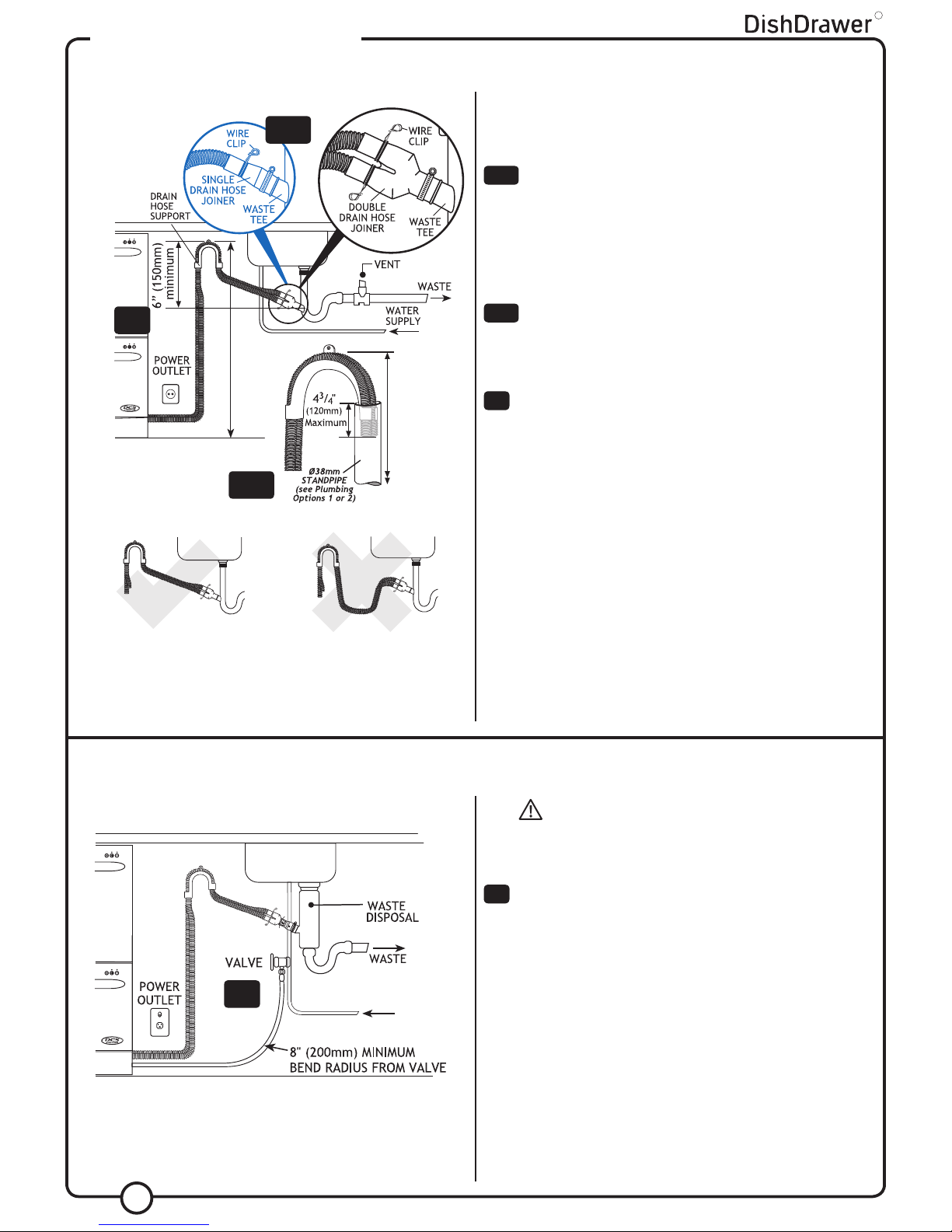
INSTALLATION PREPARATION
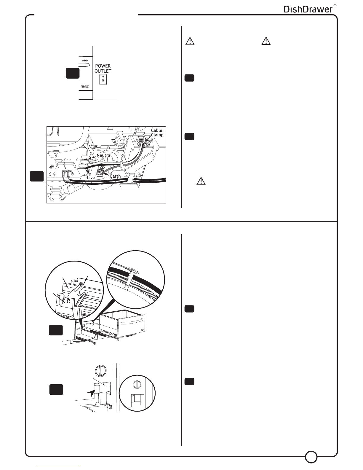
ELECTRICAL PREPARATION
A) The switched power outlet must be outside the DishDrawer®
cavity so that it is accessible after installation.
B) The switched power outlet must be between 6” (150mm) and
18” (450mm) from the DishDrawer® cavity.
C) Refer to Page 9, Step 5 for electrical connection options.
Important!
The services hole in the DishDrawer® cavity needs to be large
enough for the plug on the power supply cord to fit through, but MUST
NOT be more than 11/2” (38mm).
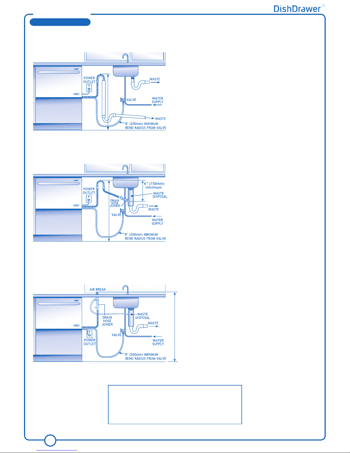
PLUMBING & DRAINAGE PREPARATION
A) A readily accessible valve must be installed in the water supply pipe.
B) If the supply pressure exceeds 145 psi (1000kPa), then a pressure
limiting valve must be used.
C) Review Plumbing Options on pages 4 & 6. Choose a method that best
suits your needs.
D) A Drain Hose extension Kit P/N 525798 will extend the drain hoses
by 1413/4” (3.6m). The kit is available from the nearest Fisher&Paykel
Authorized Service Agent. DO NOT extend beyond this limit.
E) This Dishwasher’s maximum drain height is 371/2” (950mm).
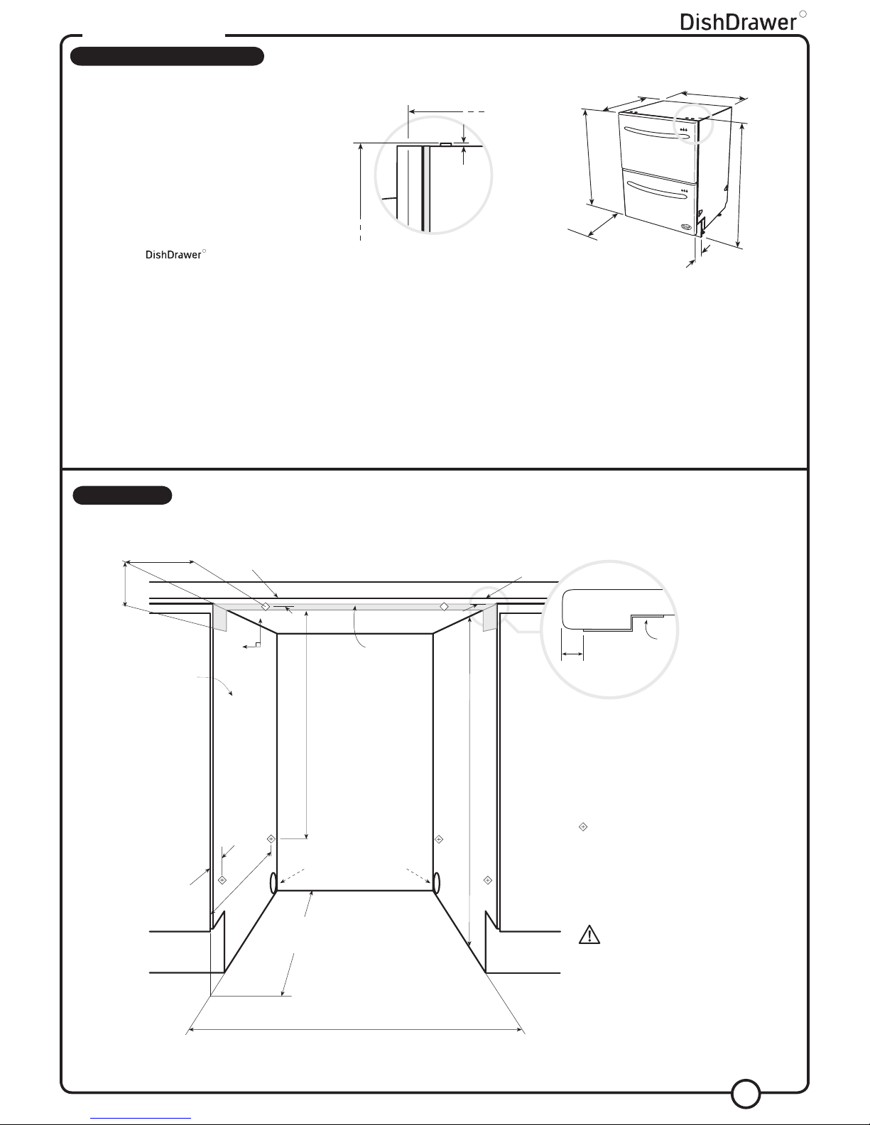
CAVITY PREPARATION
A) It is recommended that all cabinetry surrounding the DishDrawer®
(including the underside of the countertop) is sealed with an oil based
paint or moisture-proof polyurethane to prevent possible steam
damage. The air in the cavity can get very hot and humid (saturated
at 122oF/50oC)
B) The self-adhesive moisture protection tape must be applied to the
underside of the countertop to prevent moisture damage, (refer to
cavity diagram pg 3 or 5). Be sure surfaces are dry and dust-free
prior to application.
C) Be sure the cavity provides sufficient material to secure the DishDrawer®
using the mounting tabs (refer to step 1, page 7). If there is
nothing to screw to, add a brace. See page 3 or 5 for screw locations.
D) The services hole MUST be immediately adjacent to the rear lower
corner of the cabinetry. If not, the hoses will prevent the DishDrawer®
being pushed back into the cavity all the way. The hole
can be located on either side depending on the location of the
services.
E) Be sure the cavity sides are plumb (vertical) as this will assist with
levelling the DishDrawer® .
F) Minimum clearances:
ELECTRICAL INFORMATION
POWER SUPPLY CORD
A) Care should be taken when the appliance is installed or
removed to reduce the likelihood of damage to the power
supply cord.
B) If the power supply cord is damaged, it must be replaced by
the Manufacturer, Service Agent or a similarly qualified person
in order to avoid a hazard.
GROUNDING INSTRUCTIONS
A) This appliance must be grounded. In the event of malfunction or
breakdown, grounding will reduce the risk of electric shock by
providing a path of least resistance for electric current.
2
WARNING!
Improper connection of the equipment-grounding conductor can result
in a risk of electric shock. Check with a qualified electrician or
service representative if you are in doubt as to whether the appliance
is properly grounded.
B) This appliance is equipped with a power supply cord having an
equipment-grounding conductor and an earthing plug. The power
supply plug must be plugged into an appropriate outlet that is installed
and earthed in accordance with all local Codes and Ordinances.
WARNING!
Do not modify the power supply plug provided with the appliance - if
it will not fit the outlet, have a proper outlet installed by a qualified
electrician. Do not use an extension cord, adaptor plug or multiple
R
1/8” (2.5mm)
1/8” (2.5mm)
1/2” (13mm)
DOUBLE MODELS
Drain Hose
Support (1)
Drain Hose
Joiner (1)
Wire
Clips (2)
Installation Tabs (2)
Phillips 16mm
Screws (7)
Prefinished
Toe Kick (1)
White prefinished toe kick kit p/n 526678
or Black prefinished toe kick kit p/n 526679
or Iridium prefinished toe kick kit p/n 527109
Moisture
Protection
Tape (1)
p/n 527208
Drain Hose
Support (1) Drain Hose
Joiner (1)
Wire
Clip (1)
Phillips 16mm
Screws (5)
Moisture
Protection
Tape (1)
p/n 527208
SINGLE MODELS
TOOLS NEEDED
Wooden Chopping Board Drill & No.2 Phillips Bit
Tape Measure No.2 Phillips Screwdriver
Spirit Level Flat Screwdriver
Safety Glasses Adjustable Wrench or M5 Socket
Utility Knife Ø11/2” (38mm) Hole Saw
Pencil Side Cutting Pliers
Sandpaper
SPARE PARTS INSTALLATION KIT FOR SINGLE & DOUBLE MODELS: p/n 526676
Washer
(1)
Clamp
(1)
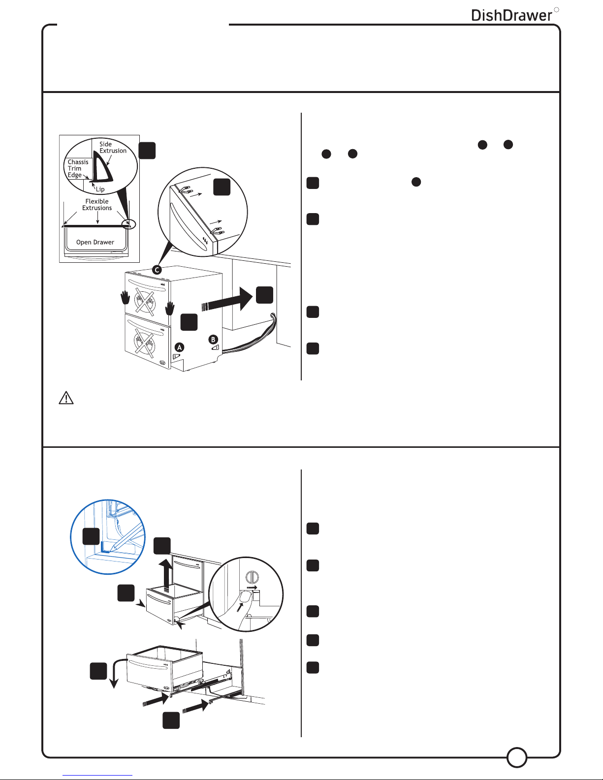
Edge Protector (1)
Flexible Extrusion
for Sides (2)
Flexible Extrusion
for Top (1)
Edge
Protector (1)
Flexible Extrusion for Sides (2) Clamp (1) Washer (1)