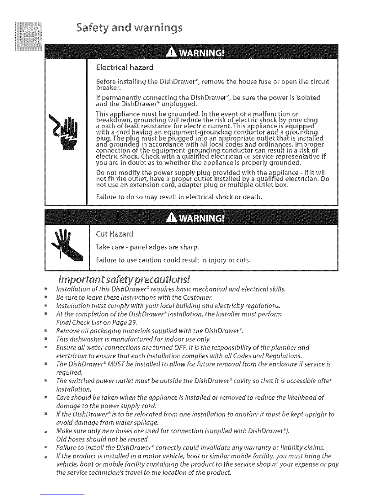
DCS DishDrawer DD124P5 User manual

DISHDRAWER®
Installation Guide
MODELS:
DD124P5
DD224P5

Safety and warnings
Electrical hazard
Before installing the DishDrawer ®,remove the house fuse or open the circuit
breaker°
If permanently con!]ecting the DishDrawer ®, be sure the power is isomated
and the DishDrawer -_unp[uggedo
Failure to do so may result in electrical shock or death°
_ Cut Hazard
Take care - pane[ edges are sharp,
Failure to use caution could result [n injury or cuts°
Instatlation of this DLshDrawer_ requires basic mechanical and electrical skills°
Besure to leave these instructions with the Customer.
installation must comply with your local building and electridty regulations.
At the completion of the DishDrawer ®installation, the Instafer must perform
Final Check List on Page 29.
Remove a# packaging materials supplied with the DishDrawer®°
This dishwasher is manufactured for indoor use only.
Ensure all water connections are tumed OF£1t is the responsibility of the plumber and
electrician to ensure that each installation complies with aH Codes and Regulations.
The DishDrawer ®MUST be installed to allow for future removal from the enclosure ff service is
required.
The switched power outlet must be outside the DishDrawer ®cavity so that it is accessible after
installation.
@re should be taken when the app#ance is installed or removed to reduce the #kelihood of
damage to the power supply cot&
ff the DLshDrawer ®is to be relocated from one instaflation to another it must be kept upright to
avoid damage from water spillage°
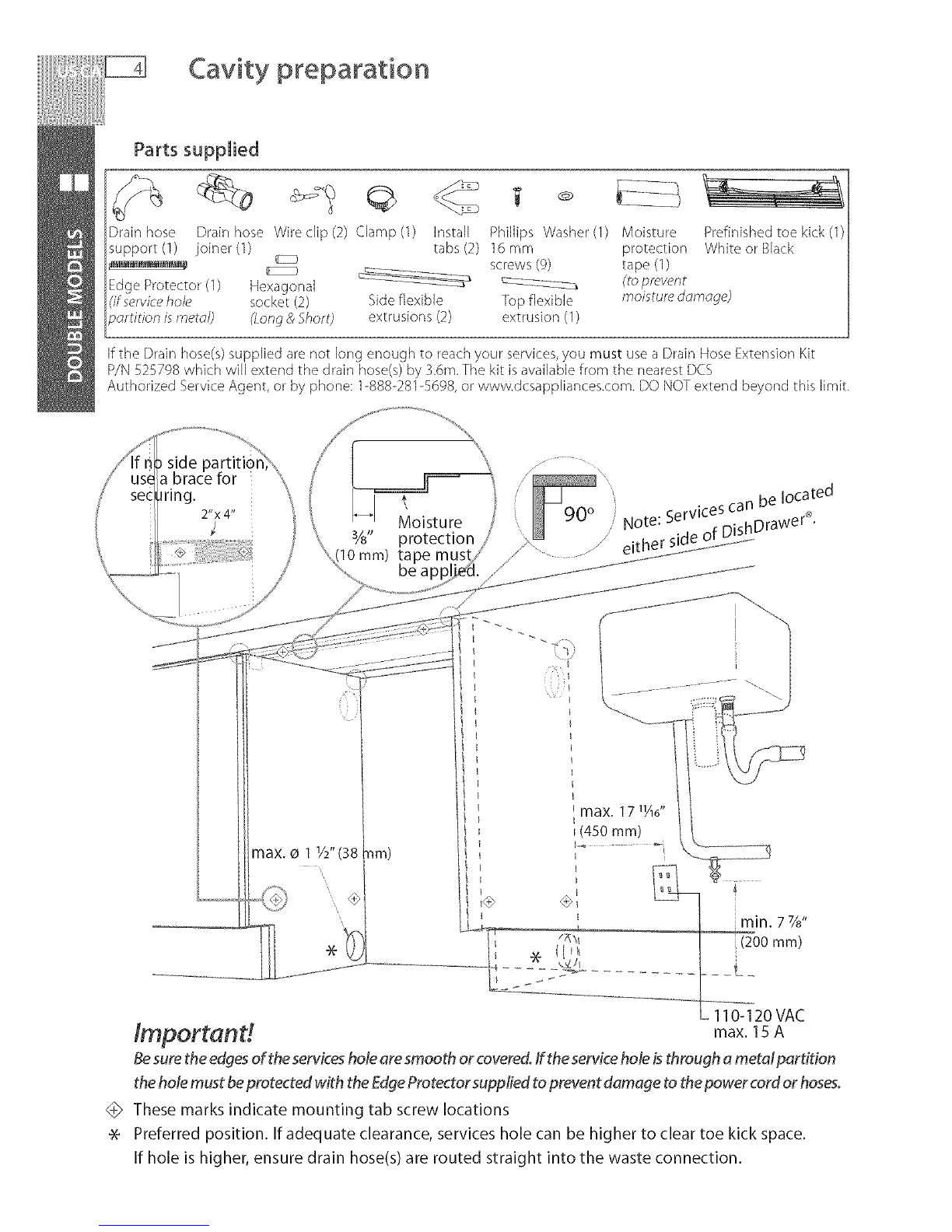
Make sure only new hoses are used for connection (supplied with DishDrawer®)°
Old hoses should not be reused.
Failure t_ install the DishDrawer_ c_rrec_y could invalidate any warranty or liabii#y daims_
ff the product LsinstaNed in a motor vehicle, boat or similar mobile fadlity, you must bring the
vehicle, boat or mobile fadfty containing the product to the service shop at your expense or pay
the service technidan_s travel to the tocation of the product.

DOUBLE MODELS
Product and cabinetry dimensions
Installation
Cavity preparation
Optionally hard wiring the product
Route the hoses and move into the cavity
Removing the tub and levelling the product
Secudng the product and refitting the tub
Fitting the toekick
Plumbing and drainage oOP'T'ION1
Plumbing and drainage oOPTION 1 (connection
Plumbing and drainage oOP'T'IOB_2
Plumbing and drainage oOPTION 2 (connection
Plumbing and drainage oOPl'lOB_ 3
Plumbing and drainage OPl'lON 3 (connection
SINGLE MODELS
Product and cabinetry dimensions
Installation
Cavity preparation
Optionally hard wiring the product
Route the hoses and move into the cavity
Removing the tub and securing the product
Plumbing and drainage oOP'T'IONI
Plumbing and drainage oOPTION 1 (connection
Plumbing and drainage oOPl'lOB_ 2
Plumbing and drainage oOPTION 2 (connection
Plumbing and drainage oOPl'lON 3
Plumbing and drainage OPTION 3 (connection
Refitting the tub
Final checklist
4
5
6
7
8
9
10
11
12
13
14
15
16
18
19
20
21
22
23
24
25
26
27
28
29
lmportand
SAVE THESE INSTRUCTIONS
ThemodelsshowninthisUserGuidemaynotbeavailableinallmarketsandare
subjecttochangeatanytime.Forcurrantdetailsaboutmodelandspecification
availabilityinyourcountry,pleasegotoourwc,bsitewww.dcsappliances.comor
contact your iota/DCS Customer (?are Representative.

Product dimensions
hlst'Jii'J_io_ f£,grc,£'is _orii _istl_¢io_ oii_;>osus o_i
Product dimensions (inches (mm)) _ _-
32 _4- 34 s/d'
Aoverall height _ of product (819.5- 879.5)
B overall width of product 23 SA6"(605)
C overall depth of product (exd d rva ure/ha_dle) 22 sad'(570)
Ddepth of drawer (opt,9 (_xd curva ure/handk_) 20 8A6"(520)
E height" ofchassis 31 7/d'(809)
Fheight range of levelling feet 2 3/8"(60)
Gdepth of chassis 21 3_,,(552)
Hdepth of drawer front panel (e×(l.culvature/hande) 1" (25)
[ depth of handle 3 3A6"(81)
Jdepth of kickstrip 2 - 4 sad' (50- 110)
Kheight of uppe_ drawer front 15 11A6"(398)
Lheight of lower drawer front 14"(356)
M heightofkickstrip(adjut hie) 2 34-4 34"(70 - 120)
Nheight of instdhtion tab slots (_r topof_ _asi9 SA" (2)
0height of drawer fronts 30 ¼6" (764)
P height'_oftop ofupperdrawerto topofchassis s4" (2)
Chasss heights ncudetab slots

Cabinetry dimensions
D A
E
Cabinetry dimensions (inches (ram)) __
_4o_d
_o__
32 sA0- 34 3_,,
A inside height o[: cavity (820- 882.5)
B in ide width ofcavity 24"(610)
C inside depth of cavity (nsid_) 22 7/8"(580)
Dheight of adjacent cabinetry 28 3/8"(720)
Eheigh_ of kickstrip 23/4-43/4"(70-120)
Minimum clearances (inches(mm))

3/811
mm)
Moisture
protection
// ............... \
....i_ 90 ° .ces can be locatedote: SerVl _ _n wer ®.
...._ /, N _ uisu_,ra
max. o 11/2"(38 nm)
_mpor_nt_ max. 15 A
Besurethe edges of the services hole are smooth or covered. If the service hole isthrough a metal partition
the hole must beprotected with the Edge Protector supplied to prevent damage to thepower cord or hoses.
<_> These marks indicate mounting tab screw locations
* Preferred position. If adequate clearance, services hole can be higher to clear toe kick space.
If hole is higher, ensure drain hose(s) are routed straight into the waste connection.

Optionally hard wiring the product
Ensure the tub is removed and
then rotated counter-clockwise
to prevent kinked hoses.
Remove knock-out for cable
clamp. Fit suitable cable clamp for
the conduit and terminate the
wiring as shown.
0 Ensure the tub clips on
both sides are reset.
Ensure the tub is
now rotated
clockwise back.
g the tub,
the hoses are not
twisted and the latches at
the rear of each drawer
runner are facing forward.

Route the hoses and move into the cavity
1
........................................,J: If top two tabs are being used,
..... "',, 2) they're securely fitted
_ ,(ii(i:: ensure
before sliding product into
cavity.
optional
Ensurehosesand cord
are not kinked or twisted.
Flexible
_ extrusions Ifcavity is bigger than
specified (Pg 3), flexible
extrusions can be stuck along
the top and sides of the product.
Open drawer Ensure extrusions do not prevent
the drawer from closing completely.
Loosen feet first, but
do not fully extend
until product is in cavity.

Removing the tub and levelling the product
// Ensure the tub is removed and
"/ then rotated counter-clockwise
to prevent kinked hoses.
Ensure product is level. Using the most appropriate length
Hexagonal socket supplied, and a screwdriver, fully extend
levelling feet up to required distance.
Hexagonal socket

Securing the product and refitting the tub
The mounting tabs
are in pairs,one on
each side of the optional CC
product. At leasttwo _,,_..............
setsof tab pairs must 3/,',
beused, max. Y4 (]gmm)
Aand Btab pairs
ORB and Ctab pairs
or all three pairs.
Ensurethe sound
insulation is
repositioned
correctly.
I
Ensure the tub clips on
(_'::_ both sides are reset.
% !
.....J
Before refitting the tub,
ensure the hoses are not
twisted and the latches at
the rear of each drawer
runner are facing forward.
Ensure the tub is
now rotated
clockwise back.

Fittin 9 the toekick

/_7¸¸ x ...................
7: ......................................................
Drain hose 79" 71"
(2011 mm) (1794 ram)
Inlet hose 61" 53"
(1561 mm) (1344 mm)
Power cord 70" 61"
(1776 mm) (1559 mm)
ILefthand
side
Water Pressure Max Min
Water softener models 1 MPa (145 psi) 0,1 MPa (14.5 psi)
Other models 1 MPa (145 psi) 0,03 MPa (4.3 psi)
Drains will need to be separated to satisfy Kosher requirements. We suggest you confirm
acceptability with your local Rabbi in respect to Kosher installations.

Plumbing and drainage - OPTION 1 (connection)
DishDrawer ®with Waste Disposal
If space is limited
.....................................................................................for fixing, push hose
through drain hos
................................................................................................support to requi
: tb joiner. Remove
_Osematerial if
!r).
i/ / /
i i /

Plumbing and drainage ,oOPTION 2
i DishDrawer ®using Air Break with Drain Hose Joiner
'_ top of Air Break
_j_:::_ (countertop or
wallmounted)

Plumbing and drainage - OPTION 2(connection)
DishDrawer ®using Air Break with Drain Hose Joiner
Ensure hoses are routed
straight to joiner. Remove
excess hose material if
/..............................................................................................................

op

Plumbing and drainage - OPTION 3 (connection)
DishDrawer ®and Standpipe D1 1/I' (38 ram)
If space is limited
for fixing, r

-7 Product dimensions
hlst'JiJoFio; rio:ton% "oI ii usFmFio; bii¢;_osus o; J
Product dimensions (inches (mm))
A overall height _ of product 16ys"(409)
B overall width of product 23 l+Ad'(605)
C overall depth of product (exd+curvature/hande) 22 TAd'(570)
Ddepth of drawer (open) (exc curvature/handle) 201/2"(520)
E height _+of chassis 16ys"(409)
F depth of chassis 21 3_,,(552)
G depth of drawer front pane[ (exc[.CLrvatLre/handle) 1" (25)
Hdepth of handle 3 346"(81)
I height of drawer front 151¼6"(398)
J height of venting area at base of product 3/s"(9)
Kheight of installation tab slots (ontopdchass+s) ¼6"(2)
Lheight :_of top of d rawer to top of chassis ¼6"(2)
++Chassisheights include tab s[ots
Note: for Prefin shed Flat door modeB, the height flora the top of handle to die top oFdoor - 2 _," (595 rnm)

Cabinetry dimensions
Cabinetry dimensions (inches (ram))
¢_ 0
A inside height of cavity 161A'(412)
B inside width of cavity 24"(610)
C inside depth of cavity (inside) 22 Ys"(580)
D clearance below benchtop Min,Ys"(3)_
Clearance is measured from the underside of benchtop to the chassis
Minimum clearances (inches(mm))

÷
min. 7Ys"
tI (200 mm)
110-120VAC
Adjacentcabinetrymustnot max. 15A
extend above cavity base
lmportand
Besurethe edgesoftheservicesholearesmoothor covered,if theserviceholeisthrough a metalpartition
theholemustbeprotectedwith theEdgeProtectorsuppliedtopreventdamageto thepowercordorhoses.
These marks indicate mounting tab screw locations
Note: Toalign drawer front to adjacent cabinetry, the product to counter top clearance can be
increased to 1/s"(3 ram).
Preferred position. Ifadequate clearance, services hole can be higher.
If hole is higher, ensure drain hose(s)are routed straight into the waste connection.
Other manuals for DishDrawer DD124P5
3
This manual suits for next models
1
Table of contents
Languages:
Other DCS Dishwasher manuals

DCS
DCS DishDrawer DD224P5 User manual

DCS
DCS DishDrawer DD24DUT7 User manual

DCS
DCS DishDrawer DS224 Series User manual

DCS
DCS DishDrawer DD24DUT7 User manual

DCS
DCS DD24SUT User manual

DCS
DCS DishDrawer DD24 series User manual

DCS
DCS DishDrawer DD24DUT7 User manual

DCS
DCS DishDrawer DD124P5 User manual

DCS
DCS DD24SUT7 User manual

DCS
DCS DW-24SS Technical manual