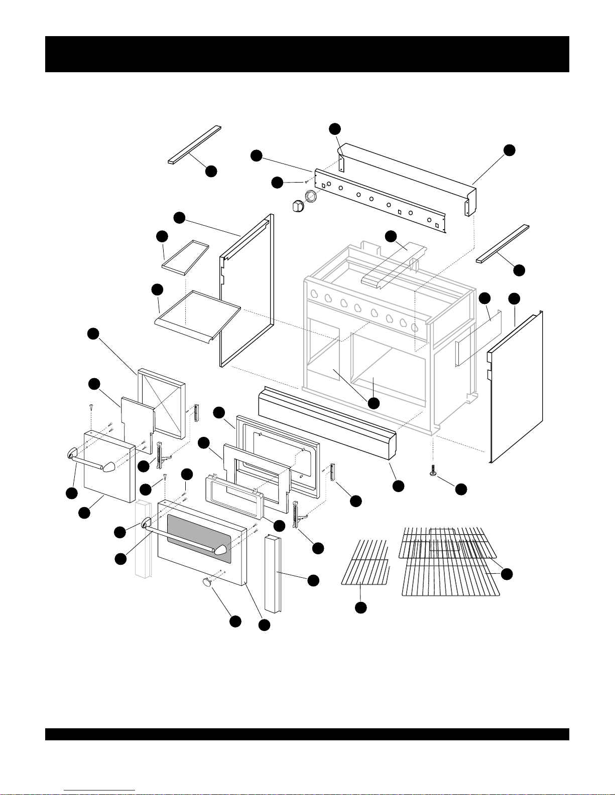
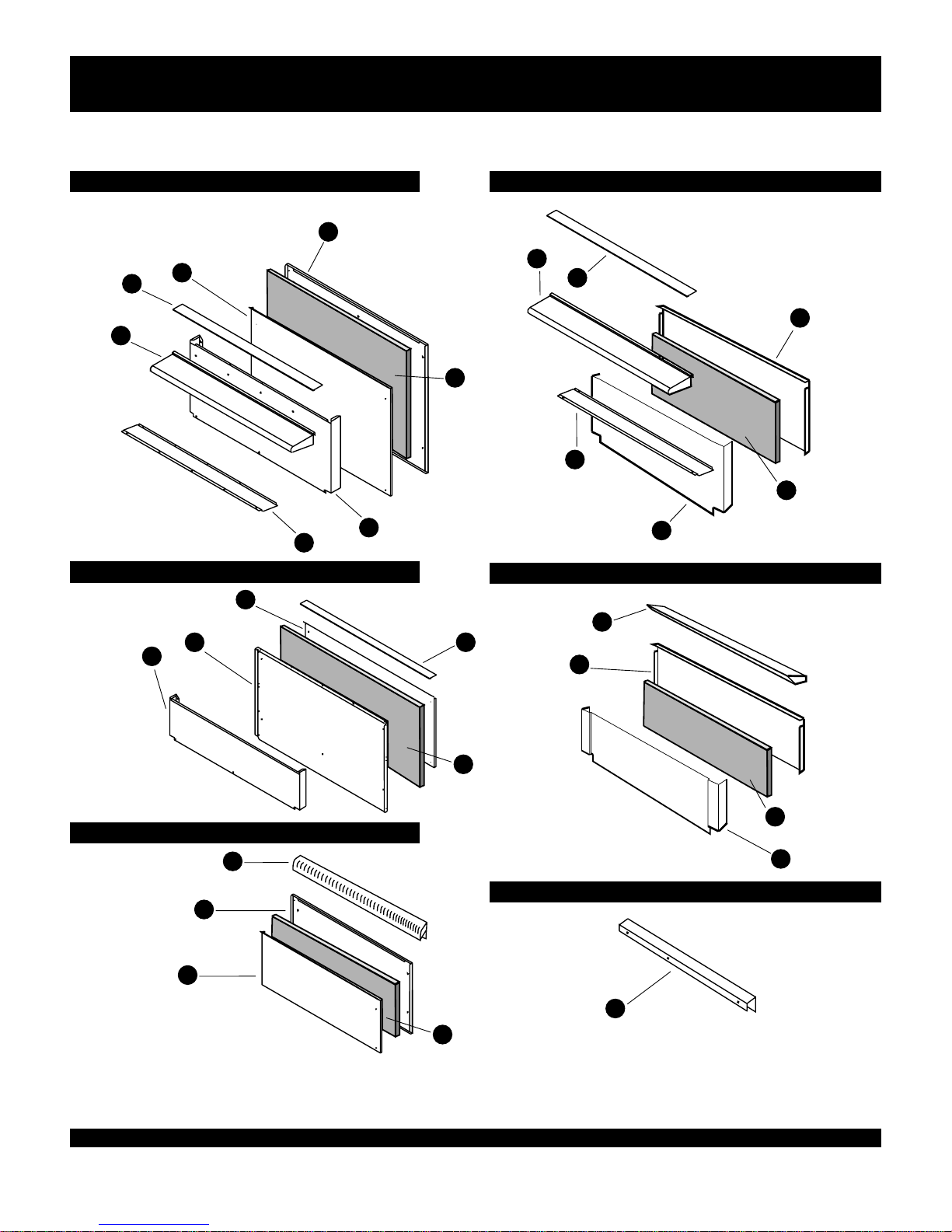
DCS RG series Datasheet

Dyn
a
mic Cooking Systems, Inc.
PROFESSIONAL
48”, 36”, 30” ALL-GAS RANGE,
48” AND 36”GAS COOKTOP MODELS
Retain this manual forfuturereference.
PPAARRTTLLIISSTT//SSEERRVVIICCEE
MMAANNUUAALL
RG
CANADIAN GAS ASSOCIATION
APPROVED
R

Asproductimprovementisanongoing
processatDCS,wereservethe right to
changespecificationsordesignwithout
notice.
Litho in USA
P/N 10582 REV 2 6/98
5800 Skylab Road Huntington Beach, CA 92647
(714) 372-7000 Fax (714) 372-7001
Direct Parts/Customer Service (888) 281-5698 Dynamic Cooking Systems Inc.

INTRODUCTION
ThisservicemanualcoversModels DCS-(RG)
(C) - (30) (36) (48) - (4) (6)-(GD) (GL) (GG)
The DCS Professional SeriesofGas Ranges
wasdesignedtoprovidefeatures tailored to a cus-
tomerwithhighexpectations. ThisService Guide was
cr eatedwiththe goalofminimizing customer incon-
venienceandhavinganynecessaryrepair s done
quickly andcorrectly. If, in the courseofusing this
manual,youshouldhaveany difficulty, or youfeel
that someimportant item has been omitted,pleaselet
usknow withaphone call orFax.
T hismanualwascreatedforuse byaqualified
technician,authorized by the DCS Service
Department.
To identify the Model and Serial #, locateand
readtheapplianceratingplate. Theratingplateis
located on the rear leftsideoftheinteriortop bur ner
box(remove the top burnergratesandbowls),oron
therightsideoftheburnerbox onsomesixbur ner
models. In general, our Model numberinglogicisas
follows; 1 2 3 4
ie. DCS-RG-484GG
1)(RG)denotes aRangewithgasovensand
anintegralgascooktop,(C)denotesagascooktop.
2) (48 )[47 7/8],(36 )[35 7/8],or(30 )indicates
unitnominalWidth(ininches)
3)(4),or(6)indicates # of open top bur ners
4)(GG)indicatesaGriddleandChar-Rock
Grill,(GD)indicatesathermostaticallycontrolled
Griddlesection,or(GL)indicatesaChar-Rock Grill
section Beforeservicingtherange,itisfirstimportant
toaccurately definetheexactdetailsofthecomplaint
andthenassessthecauseofthedefect. Complete
InstallationInstructionsareincludedwitheachappli-
anceandshouldbeconsultedtocheckforproperinstal-
lationpractices.ChargesrelatedtoInstallationare not
coveredunderwarranty. Common foraproductthis
largeandheavyisdamage duetorecklesshandlingby
tr uckingfirms,orInstallationpersonnelmovingthe
productintoposition.
What followsisanoverview of DCS warranty
provision.Reviewthewarrantypolicytodetermine
whatiscoveredunderthewarrantyrepairprovisions
andwhatwillnot be covered.Beforebeginningany
work,theproposedserviceshouldeitherbeauthorized
by DCS,or,intheeventthework isnotcoveredunder
warranty, thecustomerbeinformedoftheirresponsibil-
ityfortherepaircharges.
Introduction / Warranty Introduction ...................1
Warranty Information..................................................2
Troubleshooting-General ...........................................3
Orifice Hood / Pin SizeChart- L.P / Nat. Gas..3
Model Identification ................................................4-5
Outer Body Parts.......................................................6-7
Backguards .................................................................8-9
Open Top Burners Partlist.................................10-11
Troubleshooting - Leaks ..........................................12
Troubleshooting - Open TopBurners ................12
Griddle Partlist ......................................................13-14
Troubleshooting - Griddle .................................15-16
Grill Partlist ............................................................17-18
Troubleshooting - Grill .......................................19-20
Large Oven / Broiler Partlist............................21-22
Troubleshooting - Oven / Broiler....................23-25
Small Oven Partlist...............................................26-27
Troubleshooting - Small Oven..........................28-29
DCS SERVICE MANUAL
1
TABLE OF CONTENTS:

WARRANTY
2
Forwarrantyservice,contactyourlocalDCSauthorizedserviceagency.Providehimwiththe Model #, Serial #, gas
typeanddate ofinstallation,andabrief descriptionoftheproblem. If youneedassistanceinlocatingtheauthorizedser-
viceagencyinyourarea,contactyourlocaldealer.HewillhavealistingofauthorizedDCSserviceagentsinyourarea. We
wantyoutoremainasatisfiedcustomer.Ifaproblemdoescomeupthatcannotberesolvedtoyoursatisfaction,pleaseletus
know. Write: Dynamic CookingSystemsInc.,CustomerService Department,5800Skylab Road,
Huntington BeachCA92647.Orcall(714)372-7000orfaxusat(714)372-7001.
Thiswarrantyappliestoappliancesusedinresidentialapplications;
itdoesnotcovertheiruseincommercialsituations.Thiswarranty
isforproductspurchasedandretainedinthe50statesofthe
U.S.A.,the District of Columbiaand Canada. This warranty
appliesevenifyoushouldmoveduringthewarrantyperiod.
Shouldtheappliancebesold bytheoriginalpurchaser duringthe
warrantyperiod,the newowner continuesto beprotected until
theexpirationdateoftheoriginalpurchaser'swarrantyperiod.
Thiswarrantygivesyouspecificlegalrights.Youmayalsohave
otherrightswhichvary fromstateto state.
Allrepairlaborand replacementparts, forparts foundto be
defective,withinthewarrantyperiodduetomaterialsor work-
manship.Service must be providedby Authorized Factory Agent
duringnormalworkinghours.
Installationorstart-up
Normaladjustment to burners,gas regulators, etc.
Cleaningof igniters and/orgeneralmaintenance
Shippingdamage
Servicebyan unauthorizedagency. Damageorrepairsdueto
servicebyan unauthorizedagency ortheuseofunauthorized
parts.
Overtime,weekends, holidaylaborrates
Discolorationof the griddle plate
Improperinstallation, suchas: no regulator, improper hook-
up, etc.
Chippingofporcelainenamel grates
Service visits to:
-Teach you how to use the appliance.
- Correcttheinstallation.(Youareresponsibleforprovidingelec-
tricalwiring,gasinstallationandotherconnectingfacilities.)
-Reset circuitbreakers or replacehome fuses.
- Damagecaused fromaccident, abuse,alteration, misuse,
incorrectinstallation or installationnot in accordance with
localcodes.
-Repairs duetoother thannormalhousehold use.
- Unitsinstalled in non-residential applicationssuchas:
day care centers, bed and breakfast centers, churches,
nursing homes, restaurants, hotels, schools, etc.
One (1) YearFull- Covers the entireproduct
Five(5)Years Limited - Surface burners, Griddle burners, Grill burner, Ovenburner
Ten (10)Years Limited - Porcelain oven, Porcelain inner door panels
Thiswarrantycovers the followingcooktopsandranges. DCS RG 484 GG, DCS RG 486 GL, DCS RG486
GD, DCS RG 364 GD, DCS RG 366, DCS RG 364 GL, DCS RG 304, DCS C 486 GL, DCS C 486 GD, DCS
C 484 GG, DCS C 364 GD, DCS C 366, DCS C 364 GL.
HOW TO OBTAIN SERVICE
DCS WILL PAY FOR::
LENGTH OF WARRANTY
DCS WILL NOT PAY FOR::

STEP ONE: ISOLATING THE PROBLEM
NOTE: Beforeaddressing any specific
problem the unit mayhave, it is advisable to help
isolate the nature of the problem byrunning a
general check of the 1) Gas Supply and 2)
Electrical Supply. Thefollowing procedure will
narrow the possibilities and help direct youto
the source of the problem. A detailed
Troubleshooting section with specific symptoms
and likelycorrectivecourses of action follows
each sub-assemblyPartlist section.
CHECK GAS SUPPLY
First,check to see if the gashasbeenturnedon.
Next,gainaccesstotheregulatorbyremov-
ing the gratesover the cooktop burners on the far
lefthandsideofthecooktop.Beneath the grates,
towardstherear oftheburnerbox,the regulatoris
located between the manifoldandrearincominggas
line. Check the top of the regulator tosee that it is set
upforthetype of gassuppliedto the unit. Thecap
on top of the regulatorindicateswhethertheunitis
setupfor NATURAL or L.P.gas.
Whenthe gassupply is on, check the gas
pressure with a manometer. Thefront main open top
burner orifice is the most convenientplaceto check
gaspressure. To accessthemainburnerorifice,
remove the four(4)screwsthat hold the bur ner
hang er down and A) moveasidetheburnerassembly
or B) disconnecttheigniter wiresandremove the
entire burner /hangerassembly. Hookupaflexible
line to the main burnerorifice, turnthat burner on...
thepressure shouldread 5.0" W.C. forNaturalGas,
and 10.0" W.C. for L.P.Gas. Turn on other burners
andcheck foran excessivedrop in pressure. A large
drop in pressure indicatesagassupplyproblemrelat-
edtoinstallation, not covered byservicewarranty.
CHECK ELECTRICAL SUPPLY
First,check tosee if theelectricity hasbeenturnedon.
Next, checkpowerto the cordinthebackof
therangeandat the wallreceptacle. If power is OK
there, the nextareatocheckwill beatthe servicedis-
connect located behind the valve panel. The Valve
Panelcan beremovedbyremoving the five(5)screws
that hold it in place. Two(2)screwsarelocatedat
each end of the panel, whileone (1)screw(painted
Red)behindaBurnerControl knob mustalsobe
removed before the valvepanel canbe removed.
Once the ValvePanelhasbeenremoved,unplugand
checkforpower to the femaleside of theplug.
Between 110 & 120 voltsshould bepresent, if not,
there is a problem with the cord.
Checkforpowerat the TerminalBlocks,
(Black= Live, White = Neutral)
ORIFICE or PIN SIZE References:
Gas Type IncomingPressure Pressure Regulator
to Regulator Supplies
NATURAL 7.0" to 9.0" W.C. 5.0" W.C.
L.P. 11" to 14.0" W.C. 10.0" W.C.
Orifice Size Pin Size Orifice
Size Nat. (DMS) LP (DMS) LP (DMS)
Open Top 51 57 50
CenterSimmer 78 87 80
Grill 48 55 55
Griddle 48 55 55
InfraRedBroiler 47 55 55
Small Oven 48 55 55
Large Oven 38 52 52
*NOTE: EnsuretheAirShutterisinstalledwhenconverting
an I/R Broiler to L.P,. See Gas Hookup Section, Range
InstallationManual.
GENERAL INSTRUCTIONS:
3
INTRODUCTION

4
48" GAS RANGE MODEL IDENTIFICATION: 36" GAS RANGE MODEL IDENTIFICATION:
MODEL DCS-RG-484GG
MODEL DCS-RG-486GL
MODEL DCS-RG-486GD
MODEL DCS-RG-304
MODEL DCS-RG-366
MODEL DCS-RG-364GL
MODEL DCS-RG-364GD
RG MODEL IDENTIFICATION

COOKTOP MODEL IDENTIFICATION
5
48" GAS COOKTOP MODEL IDENTIFICATION: 36"GAS COOKTOP MODEL IDENTIFICATION:
MODEL DCS-C-484 GG
MODEL DCS-C-486 GL
MODEL DCS-C-486 GD
MODEL DCS-C-364 GD
MODEL DCS-C-366
MODEL DCS-C-364 GL

1
2
3
4
65
7
9
8
10
11
12
13
14
15
16
17
18
19
20
21
22
23
24
25
25
26
31
30
29
27
28
32
33
582fig02.eps
BODY PARTS ASSEMBLY
6
27” Oven Door Assembly 90184-02
12” Oven Door Assembly 90184-01
RG 304 Oven Door Assembly 90184-03

PARTS LIST:
ITEM # PART # DESCRIPTION
1 90104-01 RG 48 LANDING LEDGE
90104-02 RG 36 LANDING LEDGE
90104-03 RG 304 LANDING LEDGE
2 90100-PA RG 484GG VALVE PANEL
90100-01 RG 486GD VALVE PANEL
90100-02-PA RG 486GL VALVE PANEL
90102-PA RG 366 VALVE PANEL
90102-01-PA RG 364GD VALVE PANEL
90102-02-PA RG 364GL VALVE PANEL
90099-PA RG 304 VALVE PANEL
90101-PA C 484GG VALVE PANEL
90101-01-PA C 486GD VALVE PANEL
90101-02-PA C 486GL VALVE PANEL
90103-PA C 364GL VALVE PANEL
90103-01-PA C 364GD VALVE PANEL
90347 RGA 304 (SS) VALVE PANEL
90347-01 RGA 304 (WHITE) VALVE PANEL
90103-02-PA C 366 VALVE PANEL
3 90090-01 RG 48 RIGHT BODY PANEL
90217-01 RG 36 RIGHT BODY PANEL
90114-01 RG 304 RIGHT BODY PANEL
4 90090-02 RG 48 LEFT BODY PANEL
90217-02 RG 36 LEFT BODY PANEL
90114-02 RG 304 LEFT BODY PANEL
5 18052-02 LEVELING LEG
6 90164 RG 48 KICK PANEL ASSEMBLY
90219 RG 36 KICK PANEL ASSEMBLY
90228 RG 304 KICK PANEL ASSEMBLY
7 150034-3 HINGE RECEPTACLE
8 90186-PC 27" DOOR INSIDE LINER (RG 48/36)
90200-PC (RG 304) DOOR INSIDE LINER
9 150034-1 27" OVEN DOOR HINGE (RG 48/36)
15097 (RG 304) OVEN DOOR HINGE
10 14131 WINDOW PACK
11 90106 27" OVEN OUTSIDE DOOR PANEL (RG 48/36)
90094-02 (RG 304) OVEN OUTSIDE DOOR PANEL
11A 90184-02(27”), 90184-01(12”) OVEN DOOR ASSEMBLY
90184-03 RG 304 DOOR ASSEMBLY
12 17001 DCS LOGO -SM. (COOKTOPS)
17001-03 DCS LOGO -LG. (RANGES)
13 90187-02 27" OVEN DOOR HANDLE (RG 48/36)
90187-03 (RG 304) OVEN DOOR HANDLE
14 18164 DOOR HANDLE ENDCAP
15 90112 12" DOOR OUTSIDE PANEL
16 90187-01 12" DOOR HANDLE
17 90107 27" DOOR INSULATION RETAINER (RG 48/36)
90097 (RG 304) DOOR INSULATION RETAINER
18 90113 12" DOOR INSULATION RETAINER
19 90111-PC 12" DOOR INSIDE PANEL
20 15001-34 BOLT - DOOR HANDLE
21 15001-09 SCREW - DOOR TOP
22 90068-01-L/H, 90068-02-R/H DRIP PAN - 48"
90212-36" , 90234-30" DRIP PAN
22A 90202-02-L/H, 90202-01-R/H DRIP PAN HANDLE - 48"
90213-36" , 90208-30" DRIP PAN HANDLE
23 30313-3 DRIP PAN LINER (UNDER GRILL / GRIDDLE ONLY)
24 150034-2 12" OVEN DOOR HINGE
25 90054-01 (R), 90054-02 (L) COOKTOP 48 SIDE TRIM
90053-02 (R), 90053-01 (L) COOKTOP 36 SIDE TRIM
26 90259-01(R), 90259-02(L) RG 366 FRONT PANEL
27 90196-01-PC 27” OVEN BOTTOM
90196-02-PC 12” OVEN BOTTOM
90273-PC RG 304 OVEN BOTTOM
28 90055-01(R), 90055-02(L) C 48”, 366 only SIDE INSULATION RETAINER
90050-01(L),90050-02(R) C 364 SIDE INSULATION RETAINER
29 90163 RG / RGA CENTER SPACER- GRATE
30 19003-1(BAKE), 19003-3(BROIL) 27” OVEN RACK
19044-01(BAKE), 19044-02(BROIL) RG / RGA 304 OVEN RACK
31 19003-02 12” OVEN RACK
7
BODY PARTS ASSEMBLY

1
2
3
5
6
4
7
83
10
11
12
13
14
16
187
19
21
9
20
*[Insulation-
Part # 140092
All Models]
*Insulation
*Insulation
*Insulation
*Insulation
15
17
BACK GUARDS ASSEMBLY
8
RANGE HIGH SHELF BACKGUARD
COOKTOP LOW BACK BACKGUARD
COOKTOP ISLAND TRIM BACKGUARD
COOKTOP HIGH SHELF BACKGUARD
RANGE LOW BACK BACKGUARD
RANGE ISLAND TRIM BACKGUARD

PARTS LIST:
ITEM # PART # DESCRIPTION
1 90089 RG 48 HIGH SHELF BACK SHEET
90089-01 RG 36 HIGH SHELF BACK SHEET
90089-02 RG 304 HIGH SHELF BACK SHEET
2 90088 RG 48 HIGH SHELF INSULATION RETAINER
90088-01 RG 36 HIGH SHELF INSULATION RETAINER
90088-02 RG 304 HIGH SHELF INSULATION RETAINER
3 90041 RG 48 HIGH SHELF / LOW BACK TOP
90041-01 RG 36 HIGH SHELF / LOW BACK TOP
51147 RG 304 HIGH SHELF / LOW BACK TOP-GCRG 304
4 90240-01 RG 48 HIGH SHELF WELD ASSY.
90240-02 RG 36 HIGH SHELF WELD ASSY.
90240-03 RG 304 HIGH SHELF WELD ASSY.
5 90087 RG48 HIGH SHELF FRONT SHEET
90087-01 RG36 HIGH SHELF FRONT SHEET
90087-02 RG304 HIGH SHELF FRONT SHEET
6 90236 RG48 HIGH SHELF BOTTOM ENCLOSURE
90236-01 RG36 HIGH SHELF BOTTOM ENCLOSURE
90236-02 RG304 HIGH SHELF BOTTOM ENCLOSURE
7 90040 RG 48 LOW BACK BACK SHEET
90040-01 RG 36 LOW BACK BACK SHEET
90040-02 RG 304 LOW BACK BACK SHEET
8 90039 RG 48 LOW BACK INSULATION RETAINER
90039-01 RG 36 LOW BACK INSULATION RETAINER
90039-02 RG 304 LOW BACK INSULATION RETAINER
9 90038 RG 48 LOW BACK FRONT SHEET
90038-01 RG 36 LOW BACK FRONT SHEET
90038-02 RG304 LOW BACK FRONT SHEET
10 90245-01 RG48 TOP ASSEMBLY
90245-02 RG36 TOP ASSEMBLY
90245-03 RG304 TOP ASSEMBLY
11 90248-01 RG 48 BACK SHEET
90248-02 RG 36 BACK SHEET
90248-03 RG 304 BACK SHEET
12 90249-01 RG 48 INSULATION RETAINER
90249-02 RG 36 INSULATION RETAINER
90249-03 RG 304 INSULATION RETAINER
13 90236 COOKTOP 48 HIGH SHELF BOTTOM ENCLOSURE
90236-01 COOKTOP 36 HIGH SHELF BOTTOM ENCLOSURE
14 90240-01 COOKTOP 48 HIGH SHELF WELD ASSY.
90240-02 COOKTOP 36 HIGH SHELF WELD ASSY.
15 90371-01 COOKTOP 48 TOP CAP
90371-02 COOKTOP 36 TOP CAP
16 90369-01 COOKTOP 48 HIGH SHELF FRONT SHEET
90369-02 COOKTOP 36 HIGH SHELF FRONT SHEET
17 90370-01 COOKTOP 48 HIGH SHELF BACK SHEET
90370-02 COOKTOP 36 HIGH SHELF BACK SHEET
18 30130-48(48"), 30130-36(36") LOW BACK TOP CAP
19 30118-03(48"),30118-02(36") LOW BACK BACK SHEET
20 30128-03(48"), 30128-02(36") LOW BACK FRONT SHEET
21 90058 ISLAND TRIM - 48"
90052 ISLAND TRIM - 36"
9
BACK GUARDS ASSEMBLY

1
5
6
7
9
10
11 12
13
14
15
16
17
18
19
20
21
23
24
22
25
29
26
8
27
28
2
3
582FIGOI.eps
3PC BURNER
2PC BURNER
33
4A
33
4B
33
4C
33
OPEN TOP BURNER ASSEMBLY
*IT IS CRITICAL FOR PROPER PERFORMANCE THAT THE SWITCHES
SUPPLYING POWER TO THE SPARK MODULE ARE PLUGGED INTO
THE SAME NUMBER TERMINAL AS THE ELECTRODE SERVING THE
BURNER IS PLUGGED INTO (e.g.- OPEN TOP SPARK IGNITER OUTPUT
#1 MUST BE ON THE SAME BURNER SERVED BY THE OPEN TOP
SWITCH PLUGGED INTO POWER INPUT # 1
10
ELECTRICAL SCHEMATIC:

PARTS LIST:
ITEM # PART # DESCRIPTION
1 12112 TOP HALF GRATE
1A 15002-32 GRATE LEVELING SCREW
2 12131 SIMMER CAP
3 12130PC BURNER PORT RING
4A 12104 SIMMER TUBE CAP
4B 12102 SIMMER BURNER CAP
4C 12101 SIMMER BURNER RING
5 12105 SIMMER BURNER BOWL
6 12093 ELECTRODE
7 12094 ELECTRODE SPRING CLIP
8 15001-09 BURNER BASE SCREWS
9 15020-29 VENTURI BOLT
10 14000 VENTURI GASKET
11 12113 MAIN VENTURI, REAR
12 12115 SIMMER VENTURI, REAR
13 15004-04 VENTURI NUT
14 13236 SPARK MODULE
15 12116 SIMMER VENTURI, FRONT
16 12114 MAIN VENTURI, FRONT
17 16006 TERMINAL BLOCK
18 15109 VALVE SCREW / PLUG / WASHER
19 16075 POWER CORD - RANGES
16005 POWER CORD - COOKTOPS
20 13071 SPARK SWITCH / SIMMER, STD. BURNER
21 14006-PL BEZEL
22 14125 SIMMER BURNER KNOB
23 14124 SIMMER BLOCK O-RING
24 13070 SIMMER BLOCK
13005-80 SIMMER ORIFICE HOOD, LP GAS
13005-80 SIMMER ORIFICE HOOD, NATURAL GAS
25 13005-50 ORIFICE HOOD, LP GAS
13005-50 ORIFICE HOOD, NATURAL GAS
26 13069 SIMMER VALVE
27 12100 SIMMER BURNER BASE
28 18170 OVEN FEED ADAPTER
29 15002-02 SCREW
30 90129 BURNER HANGER
31 90085 GRATE SUPPORT(L)
32 90084 GRATE SUPPORT(R)
33 16131-01 ELECTRODE WIRE
11
OPEN TOP BURNER ASSEMBLY

LEAK / OPEN TOP TROUBLESHOOTING
WHAT TO DO: USEFUL NOTES:
Customer smells gas
at all times
Customer smells gas
onlywhen Open Top
Burners, Large Oven,
or Grill are in opera-
tion
Open Top Burner
Doesn't Light
CHECK for LEAKS at:
A) Thetwobrasselbows comingfromthe
1/2"NPT pipe between theregulatorandmanifold
B) Along the manifoldat everynut/washer
pointand plug
C) At all connection points betweentubing
andthermalvalvesat grill, griddle, and Small Oven-
(behindthefrontKick Panel) locations.
D) At the Dual ThermalValvelocated inthe
back of the rangebehind the GriddleorGrillassem-
bly.- Toaccessthe DualT-Valve, the Griddle or Grill
assemblymustbe removedalongwiththe rear
service cover.
CHECK for LEAKS at:
A) The ThermalValveandconnections
supplying the Large Ovenat the front of the unit,
behind the KickPanel, with oven on.
B) The ThermalValveandconnections
supplying the Grill, with Grill turned on.
C) O-Ring between the Simmer Blockand
Simmer Valve for all Open TopBurners,with
burners on
Isthe igniter sparking? Thespark shouldbe
jumpingtothebrassburnerring.
A)Make surethat the lead to the electrodeis
secure, as well as theleadto the SparkModule and
that there is poweralso.
B)Spark Switchesat controlknobsshouldbe
checkedforpower to and comingoutfrom(with
knob in "lite" position. If thereispowergoing to,yet
notcomingouttheotherside,replacesparkswitch.
C) See Open TopBurnerLightingand
"Adjustable Low Setting" sections in the Installation
Manual.
NOTE: If using a
soap and water solu-
tion when checking
forleaks, be careful
not to getanywater
onSpark Switches, as
doing so will cause a
short in the switch.
NOTE:It is
important that the
correct # wire be
traced from the Spark
Switch, to the Spark
Module, to the
Burner Electrode.
?
PROBLEM AREA:
12

22
1
2
5
6
8
9
10
13
14
15
7
17
16
18
19
20
3
4
11
12
21
23
24
26
25
GRIDDLE ASSEMBLY
13
ELECTRICAL SCHEMATIC:
L N

14
PARTS LIST:
ITEM # PART # DESCRIPTION
1 90254 GRIDDLE COVER
2 90140 GRIDDLE FLUE COVER
3 90192-01 GRIDDLE / GRILL FRONT TRIM
4 90192-02 GRIDDLE FRONT TRIM
5 90133 GRIDDLE PLATE ASSEMBLY
6 12005-1 GRIDDLE BURNER
7 16009-1 IGNITER
8 90141 GRIDDLE BAFFLE
9 30313-3 DRIP PAN LINER
10 90045-01 GRIDDLE TUBING
11 13073 THERMAL VALVE
12 18017 ELBOW ASSEMBLY
13 18166 MANIFOLD ADAPTER
14 18165 PIPE PLUG
15 15109 VALVE SCREW / PLUG / WASHER
16 16046-1 INDICATOR LIGHT
17 13010-3 GRIDDLE THERMOSTAT
18 14006-PL BEZEL
19 14129 GRIDDLE THERMOSTAT KNOB
20 16077 FIBERGLASS SLEEVE
21 16006 TERMINAL BLOCK
22 16075 POWER CORD-RANGES
16005 POWER CORD-COOKTOPS
23 16077 FIBERGLASS SLEEVE
24 13005-48 ORIFICE HOOD-NATURAL GAS (#48 DMS)
[ORIFICE PIN-LP GAS (#55 DMS)
(INTEGRAL TO THERMAL VA LVE)]
25 14026 GRIDDLE COVER HANDLE
15001-09 GRIDDLE COVER HANDLE SCREW (2)
26 16046-2 INDICATOR LIGHT LENS
GRIDDLE ASSEMBLY

GRIDDLE TROUBLESHOOTING
WHAT TO DO: USEFUL NOTES:
CHECK 1) the Electrical / Gas Supply asout-
lined in the GeneralInstruction section.
2)Remove Griddle plate assembly(fas-
tened by2screws in the front and 1 screwin
the back, under the flue cover- Visually check
for igniter breaka ge. If igniter is broken,
remove / replace
3)Remove Valve Panel (see General
instructions and note removal of "Red" screw
behind control knob - not on all units)
4) 120 V supplied to Thermostat from
the terminal block ?(live= black) If not, trou-
bleshoot powersupply lines, If YES,
5) Disconnect power, Removewiresoff
T hermostat & check for continuity between
T her mostat ter minals when Thermostat dial is
rotated to the ON. If there is no continuity
remove / replace Thermostat.
6) If Thermostat is OK, Remove the
wiresfrom the Thermal Valve and check for
continuity between the two (2) terminals on the
face of the valve. If none, remove / replace.
7) If the Thermal Valve is OK, Remove
the wires from the Griddle Igniter and check
the igniter leads for continuity. If none,remove
/ replace igniter.
8) If the Igniter is OK, Checkthe
NeutralReturn Wire for continuity to the neu-
tral(white) wire of the powersupply cord.
1) Verify Gas supply to the unit. Turn
the Gas supply OFF. Loosen tubing supplying
gasfrom the manifold to the Thermal Valveat
the Thermal Valve. Quicklyturnmanual valve
On, then Offwhileanassistant listens closely
for the sound of flowing gasat the loosened
end of the connection. If gas is not flowing,
check the tubing forblockage.
PROBLEM AREA:
Griddle will not
operate
Griddle still will not
operate, (Electrically
operational -
Steps 1-8 OK)
NOTE:Be careful
not to damage the
Capillarywhen
removing the Griddle
plate assembly
NOTE:-Ensureat
the supplysource
that the live and neu-
tralwiresare not
reversed ( If theyare,
this would not be
covered under
warranty)
15

GRIDDLE TROUBLESHOOTING
WHAT TO DO: USEFUL NOTES:
Ifdirt or other foreign matter is blocking gas
flow, then the supply line should be disconnect-
ed and the line purged. This procedure is not
covered under warranty.
2) If gasispresent at the Manual Valve,
and Electrical continuity of the valve exists per
Step 6 above, remove and visually check the
valve orifice forblockage. If none exists,
remove / replace Thermal Valve
CHECK 1) Gas pressure andsupply as outlined in
the "General"section.
2)Ensure the orifice hoodisnottightened
down onto the L.P. jet nested within the Thermal
Valve. 3)Adjust theairshutter closed untilthe
flameisyellow, then open slightly until the yellow
disappears.
1) Tocalibrate the Griddle Thermostat, place
areliable griddlethermometeronthecenter of the
griddleplate. Rotate the thermostat to 350°F. After 3
burnercycles, the griddleplateshouldhavereached
equilibrium.
2) (You'llneed aknob witha holedrilledthrough
thecenter toallow aflat-tipped screwdrivertobe inserted
throughit.) Withtheknobin place,insert a thin blade,
flat-tippedscrewdriverthrough theknobandnestit
intothesmallslottedscrewinthe thermostat (itmay
benecessary to clearthescrew of a smallamount of
sealant)3) Note the temperatureshown on the grid-
dlethermometer, then, whileholdingthe screwstill
withthescrewdriver,rotate the knob to the ther-
mometertemperature. DO NOT TURN THE
CALIBRATION SCREW.Resetthetemperatureand
check foraccuracy. Repeatifnecessary.
(Cont'd)-Griddle still
will not operate,
(Electricallyopera-
tional Steps 1-8 OK)
Low Flame / Heat
from Griddle Burner
GRIDDLE
CALIBRATION NOTE:Before cali-
brating the
T hermostat, ensure
that the griddle sens-
ing bulb is placed
within the small "V"
tube welded directly
to the bottom of the
griddle plate, pushed
about halfway back.
Thelarger piece of
angleiron is for
flame diffusion, not
for placement of the
sensing bulb.
PROBLEM AREA:
16

NC
NO
COM
1
18
2
3
4
5
6
7
8
17
16 13
9
19
20
21
10
12
14
15
11
22
GRILL ASSEMBLY
17
ELECTRICAL SCHEMATIC:
LIVE
NEUTRAL
*Powerissuppliedto theigniter
& thermal valvethroughthe
"common" and "NC" (normally
closed) contactsoftheswitch

PARTS LIST:
ITEM # PART # DESCRIPTION
1 90253 GRILL COVER
2 90140 GRILL FRONT TRIM
3 12108 CAST IRON GRATE
4 90262 BRIQUETTE TRAY ASSEMBLY
5 90034 GRILL U-BURNER
6 90042 GRILL BOX ASSEMBLY
7 13073 THERMAL VALVE
8 90045-02 GRILL TUBING
9 16009-01 IGNITER
10 18165 PIPE PLUG
11 13005-48 ORIFICE HOOD-NAT. GAS (#48 DMS)
ORIFICE PIN-L.P. GAS (#55 DMS)
(INTEGRAL TO THERMAL VA LVE)
12 16001 MICROSWITCH
13 13068 SIMMER VALVE-STANDARD
14 18030 ELBOW
15 15109 BOLT / GASKET
16 90260 CAM - GRILL SWITCH
17 14006-PL BEZEL
18 14130 GRILL KNOB
19 16077 FIBERGLASS SLEEVE
20 16006 TERMINAL BLOCK
21 16075 POWER CORD - RANGES
16005 POWER CORD - COOKTOPS
22 150112 SPEED CLIP - CAM - GRILL SWITCH
23 14026 GRILL COVER HANDLE
15001-09 GRILL COVER HANDLE SCREW (2)
18
GRILL ASSEMBLY
This manual suits for next models
13
Other DCS Range manuals
Popular Range manuals by other brands

Inglis
Inglis ELECTRIC RANGE Use & care guide

Whirlpool
Whirlpool RS6755XY Use & care guide

Maytag
Maytag MF5555B Use & care guide

Kenmore
Kenmore 30" FREESTANDING ELECTRIC RANGE WITH DOUBLE... installation instructions

Amana
Amana AGR6011VDB2 User instructions

Electrolux
Electrolux Perfect Set Gas Range Use & care guide