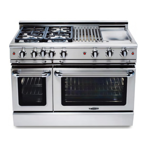
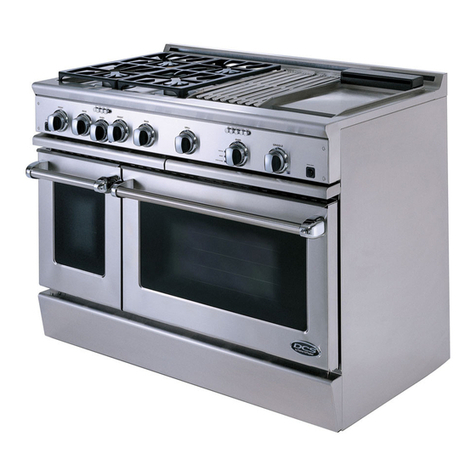
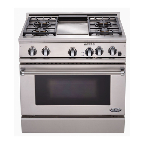
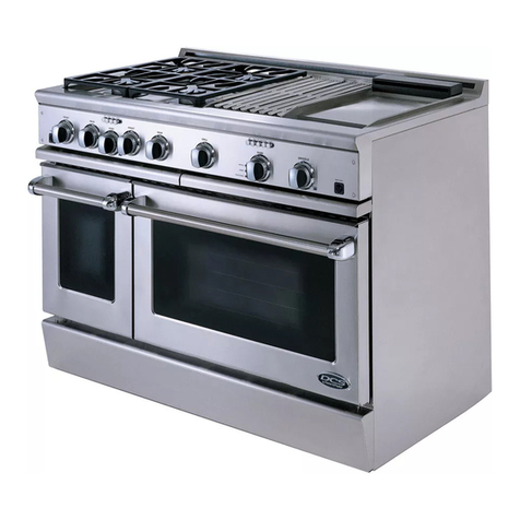
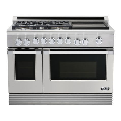
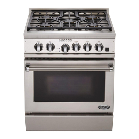
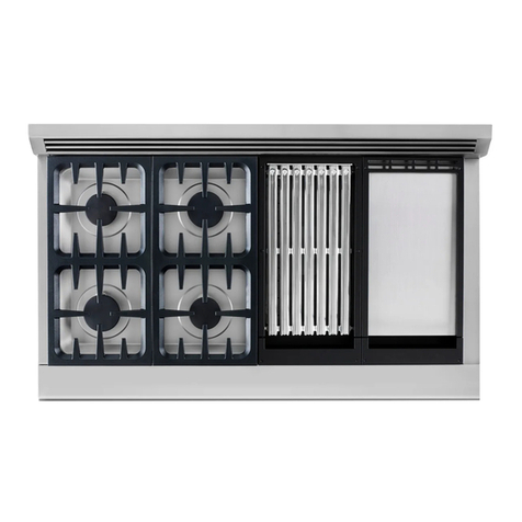
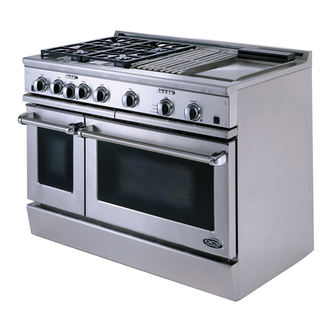
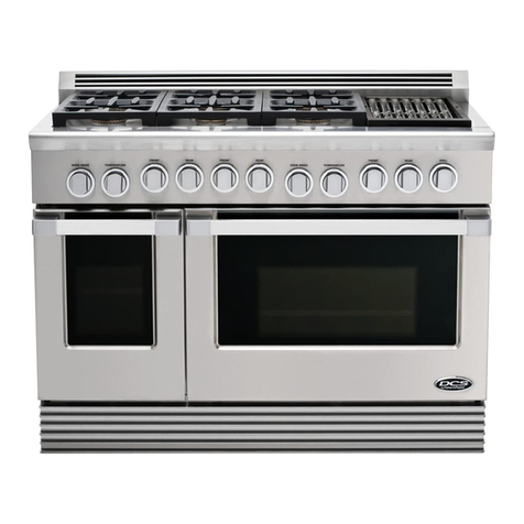
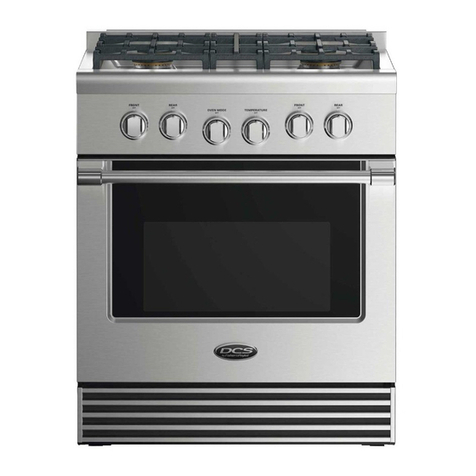
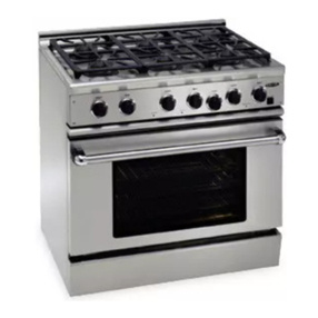
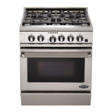
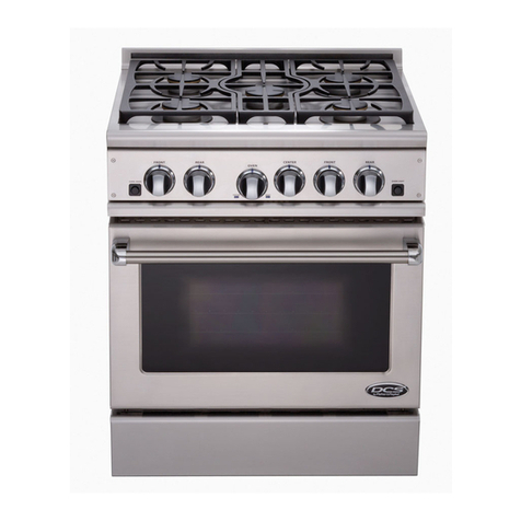
DCS RGSC-305SS User manual

PERFECT h EATs'
PROFESSIONAL 30" SELF CLEAN
RANGE
(nstallat(on Manual
MODELS
[] RGSC-305SS
[] RGSC-30SBK
[] RGSC-30SWT

NOTE TO [NSTALLER
The DCSProfessional seriesof Ranges and Cooktops are designed with a large number of features available
in a multitude of different combinations.
Foryour convenience,product questions can be answered by a DCSCustomerService Representativeby
or bymail:
DCS
Attention: CustomerService
5800Skylab Road
Huntington Beach,CA92547
www.dcsappliances.com
WARNING
If the information in this manual is not followed exactly, a fire or
explosion may result causing property damage, personal injury or
death,
PRECAUTION
Do not store or use gasoline or other flammable vapors and liquids in
the vicinity of this or any other @pliance,
FOR YOUR SAFETY
If you smell gas:
nDo not try to light any appliance,
nDo not touch any electrical switch; do not use any phone in your
building,
@ Immediately call your gas supplier from a neighbor's phone, Follow
the gas supplier's instructions,
Installation and service must be performed by a qualified installer,
service agency or the gas supplier,
PLEASE RETAIN THIS MANUAL FOR FUTURE REFERENCE,

TABLE OF CONTENTS
UNPACKING AND HANDLING
Step 3: Unpacking, Moving and Phdng the Range ................................................................................7-8
ELECTRICAL/GAS CONNECTIONS
Step 4: HectricaH Connections .............................................................................................................................9
Step S:Gas..................................................................................................................................................................9
CLEANING EXTERIORSURFACES
Step 1O:CHeaning Exterior Surfaces ...............................................................................................................13
INSTALLER FINAL CHECKLIST .........................................................................................................................14
WARRANTY .......................................................................................................................................................................1s
SERVICE .................................................................................................................................................................................16

PLANNING THE INSTALLATION
IMPORTANT INSTALLATION INFORMATION
The RGSC-305 is tested in accordance with ANSI Z21.1 Standard for Household Cooking Gas
App[hnces.
The range must be installed in conjunction with a suitable overhead vent hood. (See Step I for
ventilation requirements, page 4). Due to the professiona[ high heat capacity of this unit, particuHar
attention should be paid to the hood and duct work instaHHation to ensure it meets [oca[ building
codes. To eHiminate risk of burns or fire by reaching over heated surface units, cabinet storage [ocated
above the surface units should be avoided.
All range models with less than a 12"clearance between combustable material and the back edge of
the range, require the installation of one of the two offered Wall Mount Backguards.
Wa[[Mount Fuji
Backguard
(ModeINo.
BGS-3030)
Wall Mount
28-1/8"
FIG. 1FIG. 2
Check local building codes for the proper method of range installation. Local codes vary. Installation,
electrical connections, and grounding must comply with all applicable codes. In the absence of local
codes, the range /cooktop should be installed in accordance with the National Fuel Gas Code ANSI
Z223.1q 988 and National Electrical Code ANSI/NFPA 70-1990.
Be sure that the unit being installed is set up for the kind of gas being used. The gas range is shipped
from the factory set and adjusted for Natural Gas or LP (propane), depending on the specific mode[
ordered. Verify that the range is compatible with the gas at the installation site before
proceeding further. Return range to dealer if the unit is not set for site gas supply.

PLANNING THE INSTALLATION
Recommended Installation Instruction (when using BGS-3030 Backguard)
Install components in the following order:
a.Vent Hood b. gackguard System c. Range
1.Locate and [eve[ range according to Range installation instructions.
2. Measure distance from floor to top of isHand trim on range adding ]/8" for backguard cHearance.
3.Transfer this measurement to the waHLThis wH[ mark the bottom of your backguard.
4. From this [ine measure 28-1/8" up wall[ to mark top of 30" backguard. This is the minimum height
that the bottom of your vent hood can be instaHHed.
5. FoHHowvent hood manufacturer's instaHHation instructions to install[ vent hood.
6. Follow backguard installation instructions to install backguard.
7. Connect gas and electric connections and slide range into position.
VENTILATION REQUIREMENTS
STEP 1: VENTILATION REQUIREMENTS
A suitable exhaust hood must be installed above the range /cooktop. The following chart indicates
the minimum blower capacity recommended for hood ventilation.
VENTILATION STANDARD COUNTER ISLAND
UNIT INSTALLATION INSTALLATION
RECOMMENDATIONS RECOMMENDATIONS
HOOD (24" Deep x Unit Width) (30"Deep x 36"at Bottom)-"
BLOWER 600 CFM (rain.) 600 CFM (rain.)
CAUTION:
Ventilation hoods and blowers are designed for use with single wall ducting.
However, some local building codes or inspectors may require double wall
ducting. Consult local buiMing codes and/or local agencies, before starting, to
ensure that hood and duct installation will meet local requirements.
Hood blower speeds should be variable to reduce noise and loss of heated or air conditioned
household air when maximum ventilation is not required.
For best smoke elimination, the lower edge of the hood should be installed a minimum of 30" to a
maximum of 36" above the range cooking surface (See Fig. 3, page 5). If the hood contains any
combustible materials (i.e.a wood covering) it must be a minimum of 36" above the cooking surface.
Due to a high volume of ventilation air, a source of outside replacement air is recommended. This is
particularly important for tightly sealed and insulated homes. A reputable heating and ventilating
contractor should be consulted.

CABINET PREPARATION
STEP 2: CABmNET PREPARATmON
1. The range is a free standing unit. Hfthe unit is to be placed adjacent to cabinets, the clearances
shown in Fig. 3 are required. The same cHearances appHy to isHand instaHHations.
2. The range can be pHaced in various positions with respect to the cabinet front, with the front
either flush or projecting, depending on the countertop depth (See Fig. 5, page 6).
00 L !
35-3/8"max.forlevelcounter,
3&3/4" max.with range
levelinglegsfully extended
"As definedin the
"NationalFuelGasCode"
(ANSIZ223J,latestedition).
Therangeheight[sadjustable.The[eve[ofthe
rangetopmustbeatthesame[eve[orabovethec0untertoplevel.
A) 7q/2"
m 18"mJn.
C) 3"
D) 13"max.
E) 4-1/2" (gas)
F) 11"(electrkal)
FIG. 3
Flex Line "'-..
to Range
2" Maximum
Protrusion from Wall
for Gas Supply
FIG. 4

CABINET PREPARATION
3. The gas and eHectrkaH suppHy shouHd be within the zones shown in Fig.3 & Fig.4, page 5.
4. The maximum depth of over head cabinets instaHHedon either side of the hood is 13".
5. Any openings in the waHHbehind the range and in the floor under the range must be seamed.
6. When there is Hessthan a 12" cHearance between combustibHe materhH and the back edge of
the range, (above the cooking surface) a DCS gackguard must be instaHHed (see Fig. 5). The
range comes equipped with HsHandTrim asstandard. Fig.5 indicates the space required for each
type of backguard.
7. AHways keep the appHhnce area dear and free from combustibHe materiaHs, gasoHine and other
flammabHe vapors and Hiquids.
8. Do not obstruct the flow of combustion and ventiHation air to the unit.
Dimensions:
\\\\\\\\\\_-_%\_\\\\\\\\X_
E
0"clearance
i
joO 000 O0 O,s
B
XX\\X\%\X\\N \\\_ \\\\\\\X%\\\\%
0" clearance
A) 29-7/8"
B) 39 3/4"- 37"
E} 27-1/2"
F) 28-1/8"fullbackguacd
G/ 10-1/8" 10wbackguard
H) 2"Bland tc[m
i) 14/J6"
J) 30"
m 44-5/8"
L) 36"min,tocombustibles
M) 24-1/4"
N) 264/4"
o) 12"rain.tocombustibles'
FIG. 5

UNPACKING AND HANDLING
STEP 3: UNPACKING, MOVING
AND PLACING THE RANGE
CAUTION:
PROPER EQUIPMENT AND
ADEQUATE MANPO WERMUST
BE USED IN MOVING THE
RANGE TO AVOID DAMAGE TO
THE UNIT OR THE FLOOR. THE
UNIT 15HEAVY AND RESTSON
ADJUSTABLE STEELLEGS.
WARNING:
DO NOT LiFT THE RANGE BY
THE OVEN DOOR HANDLES !!
The range has a shipping weight of approxF
mateHy 408 pounds or 354 pounds after removaH
of packing materhHs. Htis recommended that the
door, grates and front kick paneH be removed to
facilitate handHing. This wHHreduce the weight to
about 230 pounds. It may be necessary to remove
the oven doors and knobs to pass through some
doorways. With the doors and knobs removed, a
2%3/8" wide opening is required. Without
removing the door, a 30"wide opening is required.
Remove the outer carton and packing materiaH
from the shipping base.
CAUTION:
Before using range, be sure to
remove shipping spacer insert
in broiler (See Fig. 7).
Remove the kick panel by removing two screws at
the top and pulling forward. The range is held to
the skid by two brackets in the front behind the
kick panel (See Rg.6) and two L-brackets located
on the bottom flange of the range back (See
Fig. 8). After removing the screws and
brackets,the range must be lifted and removed
from the skid. Due to the weight, a doily with soft
wheels should be used to move this unit. The
weight must be supported, uniformly across the
bottom (See Fig. 9, page 8).
Kick Panel
FIG, 6
FIG. 7
Left Rear Shipping
Screws
FIG. 8

UNPACKING AND HANDUNG
LevelingLegs
Rangeblust
be Uniformly
Supported
on E_Faces
/
22"
/
FIG. 9
To remove the door, open the door and
hoHd it aH the way open. CHose the
hinge Hatches (See Fig. 10) and reHease
the door. The door can then be
removed by gently lifting and pulling
the door, with the hinges up and out of
the frame.
The professionaH range shouHd be
transported by a dolly chose to its finaH
Hocation. The range can be tipped back
and supported on the rear Hegswhile
the dolly is removed. The floor under
the legs should be protected (wood
strips, carpet, paneming,etc°) before
pushing the unit back into position.
E[ectdc and gas connections should be
made (Steps 4,5 & 6),the anti-tip device
installed (Step 7), and the backguard
installed (Step 8) before the range usplaced in its final position. Hfthe unit is to be converted to LPgas,
it can be done with the range in place (See page 10).
For proper performance, the professional range should be [eve[. To achieve a flush fit of the range to
adjoinin 9 countertops, it will be necessary to have level cabinets (front to back, and left to right across
the opening of the range). After checking the countertops for level and before sliding the range into
place, measure the distance from the floor to
the top of the counter work surface in the
rear left and right corners. Adjust the
corresponding rear corner of the range to an
equal height of the counter, as the rear
leveling legs are not accessible once the
range is pushed into place. Once the range
is in place, the front leg levelers can be
accessed to level the front of the range.
Replace the kick panel and oven doors by
reversing the procedure described
previously, it is important that the two
screws retaining the kick panel are secure
to prevent accidental access to live
emectrical components and wires (See Fig.
6, page 7},
NOTE: For ease of installation, be sure to
install vent hood and backguard
system before sliding range into
position.
DOOR HINGI ROLLER
UN-LOCK
FIG. 10

ELECTRiCAL/GAS CONNECTIONS
STEP 4: ELECTRICAL CONNECTIONS
Receptacle Box
Cover Plate
Three
Pror
Plug
Three Prong
Receptacle
POWER REQUIREMENTS
120 VAC, 60 Hz., singHe phase. 4 Amp. Max. (Use 15
Amp. Circuit)
Always disconnect e[ectdc supply cord from the
waHHoutlet or service disconnect before servicing
this appHiance. Observe aHHgoverning codes and
ordinances when grounding, in the absence of
which, observe NationaH EHectdcaHCode ANSH/NFPA
No. 70-1990.
FIG. 71
RECOMMENDED GROUNDING METHOD
This appHhnce isfactory equipped with a power suppHy cord with a three-prong grounding pHug (with
pohrized paraHeHbhdes). Htmust be pHugged into a mating grounding type receptacle, connected to
a correctly polarized 120'v'olt circuit. If the circuit does not have a grounding type receptacle, it is the
responsibility and obligation of the installer or user to have the existing receptacle changed to a
properly grounded and polarized receptacle in accordance with all applicable local codes and
ordinances by a qualified electrician. In the absence of local codes and ordinances, the receptacle
replacement shall be in accordance with the National Electrical Code. THE THIRD GROUND PRONG
SHOULD NOT, UNDER ANY CIRCUMSTANCES, BE CUT OR REMOVED (See Fig. 11).
STEP 5: GAS
Verify the type of gas supplied to the location. The range is shipped from the factory set up and
adjusted for natural gas or LP (propane), depending on specific model ordered. The unit cannot be
converted.
NATURAL GAS REQUIREMENTS
Connection: 1/2" N.RT. Minimum 5/8" dia.flex line. Pressure: 6" to 14" W.C.
L°R GAS REQUIREMENTS
Connection: 1/2" N.RT. Minimum 518" dia. flex line. Pressure: Supply pressure must be 11" to 14" W.C.
A regulator is required at the L.R source to provide a maximum of 14" W.C.to the range regulator.

HOOKUP TO GAS SUPPLY
STEP 6: HOOKUP
A manual valve is installed in an accessible location from the front for the purpose of shutting off the
gas supply.The supply line must not protrude beyond the back of the unit.Make sure the gas supply
is turned off before connecting the app[hnce.
The flex line for the gas supply must be metal and be approved by CSA, AGA, CGA OR UL. Only use a
metal supply hose, as the heat may cause a rubber hose to melt and develop leaks.
The gas supply connections should be made by a qualified technician and in accordance with local
codes or ordinances, in the absence of a local code, the installation must conform to the National Fuel
Gas Code ANSi 223.1-1988, latest edition.
CAUTION:
The appliance must be isolated from the buiiding's gas supply piping system
by dosing its individual manual shut-off valve during any pressure testing of
the gas supply piping system at test pressures equal to or less than 1/2 psig
(3.5kPa.)
The appliance and its individual shut-off valve must be disconnected from
the gas supply piping system during any pressure testing of the system at the
test pressures in excess of 1/2 psig (3.5kPa.).
When checking the manifold gas pressure, the inlet pressure to the regulator
should be at [east 7.0"W.C. for natural gas or 12.0"for LP.
When hooking up the gas supply from range rear hard pipe to wail hard pipe, installation length of
flex line between range/wail hard piping must accommodate the range being pulled from wail for
cleaning or servicing purpose. When range is pulled from wail, no strain should occur at range or wail
hard pipe connections (See Fig. 12 below).
,ManualShut-Off
Valvemustbe
EasilyAccessible
Hard Pipe J
1/2" NPT Metal Flex Gas Line
FIG. 12
10

ANTI-TIP DEVICE INSTALLATION INSTRUCTIONS
STEP 7: ANTra-TIP DEVmCE[NSTALLATION
AH ranges must have an anti-tip device correctly installed as per these instructions. If you pun the
range out from the wan for any reason, make sure that the device is properBy engaged when you
push the range back against the waN. If it is not, there is a possibBe risk of the range tipping over
and causing injury if you or a cMd stand, sit or Bean on an open door.
INCLUDED PARTS:
hduded with this kit are:
(4) #10 x 2" wood screws,
(1) Anti-tip bracket, and (1)
HnstaHHationInstructions.
INSTALLING THE KIT:
Instructions are provided
for wood and cement
floors. Any other type or
construction may require
special installation
techniques as deemed
necessary to provide
adequate fastening of the
Anti-tip bracket to the floor
and wall. The use of this
bracket does not preclude
tipping of the range when
not properly installed.
WOOD
CONSTRUCTION:
Place the bracket against
(2) Wood Screws
into Back Wall (ALL
Installations)
(2)Small Holes for
Wood Installations
(2) Large Holes for
Concrete Installations BACK
WALL
FIG. 13
the back wail, into the right rear corner where the range is to be located. Leave a gap between the wail
(or side of range) and the bracket of 3/4'_ Drill (2) 1/8" diameter pilot holes in the center of the small
holes. A mail or awl may be used if a drill is not available. Fasten the bracket securely to the floor and
wail See Fig. 13.
CONCRETE OR CEMENT CONSTRUCTION:
HARDWARE REQUIRED: (2) sleeve anchors, lag bolts,
and washers (not provided). Locate the bracket as
described above. Drill the recommended size holes
for the hardware. Install the sleeve anchors into the
holes and then install the lag bolts through the
bracket. The bolts must be properly tightened as
recommended for the hardware. Fasten the bracket
securely to the floor and wall.
_ WARNING
ALL RANGES CAN TIP
INJURY COULD RESULT
INSTALL ANTI=TIP
BRACRET PACRED
INSIDE OVEN
® SEE INSTRUCTIONS
ONCE mNSTALLED:
Complete the range installation per the instructions provided with the product. Check for proper
installation of the Range and Anti-tip device by grasping the back of the unit and carefully attempt to
tilt the range forward. 11

BACKGUARD INSTALLATION
STEP 8: BACKGUARD [NSTALLATION
The backguard must be installed when there is less
than a 12" clearance between combustibles and the
back of the range (above the cooking surface) (See
Fig. 3, page 5).
BACKGUARD KITS:
The backguard is located, as shown in Fig. 14.
Secure the backguard to the waN[ behind the range.
Specific instructions for instaHHation of the fuN[
backguard or How backguard can be found packaged
with the backguard.
Wain Mount Full Backguard
(30") (Model No. BGS-3030) 6_,_
Wail Mount Low Backguard
(12") (Model No. BGS-1230) _ _'_
FIG. 14
STEP 9: PROPER FLAME SIZES
FLAME CHARACTERISTICS
OVEN BURNER iNFRARED BROIL BURNER
\.
S
BLUE FLAME
FIG. 16
FIG. 15
SEALED TOP BURNER LIGHTING
NOTE:
The seaHed top burners have an infinite
number of heat settings and there are no
fixed positions on the contro[ knobs
between Hi and LO.To turn the seaHedtop
burner on, push in on the contro[ knob and
turn it countercHockwise to the "LITE"
position. An audible clicking sound will be
heard. When the gas has been ignited by
the electronic spark igniter, turn the knob
to the desired setting.
COOKTOP BURNER
FIG. 17
12

FLAME CHARACTERISTICS
CAUTION:
IA/hen turning on any sealed top burner, be sure to stop at the "LITE" position
before turning the burner to aflame setting for cooking. If the burner is not lit and
it is turned beyond the "LITE"position, to HI,MEDIUM, or LQ there will be aburst of
flame when the burner does light. This could cause burns or damage to the
surrounding countertop.
CAUTION:
The oven infra-red broiler burner has no air shutter and is not adjustable. The oven
bake burner has an air shutter and is adjustable. It is necessary to operate the
oven broiler for 45 minutes to eliminate the harsh odor of the insulation binder.
This must be done BEFORE using the range for the first time and with proper
ventilation.
CAUTION:
For Warranty coverage, DCS requires that burner adjustments be made by a
qualified techn ician at the time of installation.Extreme care should be used when
adjustments are made after installation.
Improper or lack of adjustments will void your warranty°
Check for the proper burner flame characteristics (See Figs. 15-17, page 12).
Burner flames should be blue and stable with no yellow tips, excessive noise or lifting of the flame from
the burner. If any of these conditions exist, check that the air shutter (oven burner only) or burner
ports are not blocked. Ifthis condition persists, contact a qualified technician.
The sealed top burner flames should be approximately 1q/2" high.The oven burner flames should be
1q/2" to 2".The infrared broil burner flames should be approximately 1/8" high over the entire burner
screen (See Figs. 1B-17, page 12).
CLEANING EXTERIOR SURFACES
STEP 10: CLEANING EXTERIOR SURFACES
The stainless steel surfaces may be cleaned by wiping with a damp soapy cloth.Any mild glass cleaner
will remove fingerprints and smears. Do not use steel wool as it will scratch this surface. Small
scratches may be removed by lightly sanding with the grain, using 200 grit paper.
13

INSTALLER FINAL CHECKLIST
GENERAL
,I Placement of Unit.
,I Specified clearance maintained to cabinet surfaces.
_1 Unit Leve[- front to back, side to side.
_1 A[[ packaging material and tie straps removed, drip pans dean and empty.
_1 Backguard wall[ system instaHHedif there is Hessthan 12" cHearance above the cooking surface
to combustibHes behind unit.
ELECTRICAL
_1 Receptacle with 15 ampere over-current protection is provided for service cord connection.
,I Adequate ground connection.
_1 Kick pane[ (See Fig.6, page 7)in place and two (2) screws secure.
GAS SUPPLY
_1 Connection: 1/2 NPT with a minimum 5/8" diameter metal flex Nine.
_1 The pressure regulator which is connected to the manifoHd is set for 5.0" W.C. for natural gas
or 10.0" W.C.for LR
_1 Manual gas shut offvalve installed in an accessible location.
,I Unit tested and free of gas leaks.
OPERATION
_1 All internal packing materials removed. Check below grate and inside oven.
_1 Bezels centered on burner knobs and knobs turn freely.
_1 Each burner lights satisfactorily, both individually and with other burners operating at the
same time.
_1 Check flame characteristics on all burners and adjust as specified per instructions on page 12
(See Figs. 15-17, page 12).
,I Oven door hingesseatedand door opens and doses properly.
_I Burnergratescorrectlypositioned,level,and do not rock.
14

LENGTH OFWARRANTY
One (1) Year FuJI- Covers the entire product
Five (5)Years Limited - Surface burners, Oven burner
Ten (10) Years Limited - PorceHain oven, PorceHain inner door paneH
DCS WILL PAY FOR:
AHHrepair Habor and repHacement parts, for parts found to be defective due to materiaHs or
workmanship. Service must be provided by Authorized Factory Agent during normaH working hours.
DCS WILL NOT PAY FOR:
m hstaHation or start-up.
mShipping damage.
n Service by an unauthorized agency.
n Damage or repairs due to service by an unauthorized agency or the use of unauthorized parts.
n Service during other than normaH working hours.
n Hmproper installation, such as improper hook-up, etc.
m Service visits to teach you how to use the appHiance; correct the installation; reset circuit
breakers or replace home fuses.
n Repairs due to other than normal house hold use.
m Damage caused from accident, abuse, alteration, misuse, incorrect installation or installation not
in accordance with local codes.
m Units installed in non-residential application such as day care center, bed and breakfast centers,
churches, nursing homes, restaurants, hotels, schools, eL
This warranty applies to appliances used in residential applications; it does not cover their use in
commercial situations.
This warranty is for products purchased and retained in the 50 states of the U.S.A., the District of
Columbia and Canada. This warranty applies even if you should move during the warranty period.
Should the appliance be sold by the original purchaser during the warranty period, the new owner
continues to be protected until the expiration date of the original purchaser's warranty period.
This warranty gives you specific legal rights. You may also have other rights which vary from state to
state.
15

HOW TO OBTAIN SERVICE:
For warranty service, contact DCS Customer Service at (888) 281-5698. Before you call, pHeasehave
the following information ready:
[]Modal Number
[] SeriaHNumber
[] Date of installation
[] A brief description of the proNem
Your satisfaction is of the utmost importance to us, Hfa problem cannot be resolved to your
satisfaction, please write or fax or emaH us at:
Write:
DCS
Attention: Customer Service
5800 Sky[ab Road
Huntington Beach,CA 92647
Fax: (714) 372-7004
EmaH: support@dcsa pp[ia nces,com
BEFORE YOU CALL FOR SERVICE:
1.Is the circuit breaker tripped or the fuse blown?
2. Is there a power outage in the area?
16

PERFECT _EAT: _
cU A GAZ
Manuel D'lnstallation
30 PO
MODULES :
II RGSC_305SS
w RGSO3OSBK
l! RGSC-3OSWT

AVIS A L'iNSTALLATEUR
Les cuisini_res et tables de cuisson de s6de professionne]]e DCS sont dot6es de nombreuses fonctions
offertes dans une gamme de combinaisons vari_es.
Si vous avez des questions au sujet de notre produi% communiquez avec un repr_sentant du service _ la
client@le DCS par tdl_phone : 1-888-281-5698, ou par tdl_copieur : 714_677-1270, ou par email :
ou par courrier :
DCS
Attention : Customer Service,
.5800Skylab Road,
Huntington Beach, CA 92647
www.dcsappfiances.com
AVERTISSEMENT
Si les informetions de ce manuel ne sont pes suivies _ la lettre, un incendie ou
une expioMon peuvent se produire et causer des dommeges met_de/s, des
b/assures ou la mort.
MESURE DE PRECAUTION
Evitez de stocker ou d'utiliser de I'essence ou toutes autres vapeurs et fiquides
inflammables aproximit_ de cat appareil ou de tout autre appareiL
POUR VOTRE SECURITE
Si vous sentez une odeur de gaz :
nN'essayez pes d'aflumer des eppareils _lectrom_nagers.
nNe touchez eucun interrupteur _lectrique; n'utifisez aucun t_l_phone dans
I'_difice.
mAppelez imm_diatement votre fournisseur de gez de chez un voiMn. Suivez
les instructions du fournisseur de gez.
Toute installation ou service dolt _tre confi_ _un insteflateur quelifi_, un
orgenisme de service ou le fournisseur de gaz.
VEUILLEZ CONSERVER CE MANUEL A TITRE DE REFERENCEo

TABLE DES MATJ[:RES
PLANIFICATION DE L'INSTALLATION
[mportantes informations concernant Hnsta[[ation ...................................................................................3
hstructions concernant FinstaHation recommand_e ................................................................................4
EXIGENCES EN MATIERE DE VENTILATION
Etape 1 : Exigences en mati_re de ventilation ..............................................................................................4
DIeBALLAGE ETMANIPULATION
Etape 3 : D_ba[[age, d_p[acement et placement de [a cuisini@e ......................................................7-8
BRANCHEMENT teLECTRIQUEOU DU GAZ
Etape 4 : Raccordements _[ectdques ...............................................................................................................9
Etape 5 :Gaz ..............................................................................................................................................................9
BRANCHEMENT DU GAZ
Etape 6 : Branchement ........................................................................................................................................10
INSTALLATION DU DISPOSITIF ANTIBASCULEMENT
Etape 7 : Installation du dispositif antibascuHement ................................................................................11
INSTALLATION DU DOSSERET
Etape 8 : InstaLLation du dosseret ....................................................................................................................12
CARACTIeRISTIQUESDE LA FLAMME
Etape 9 : Nivea ux de flam me corrects .....................................................................................................12-13
NETTOYAGE DESSURFACESEXTIeRIEURES
Etape ] 0 : Nettoyage des surfaces ext@ieures ..........................................................................................13
MSTE DE CONTROLE FINALE DE L'INSTALLATEUR .....................................................................14
GARANTIE ...........................................................................................................................................................................is
SERVICE .................................................................................................................................................................................16
Other manuals for RGSC-305SS
1
This manual suits for next models
2
Table of contents
Languages:
Other DCS Range manuals