DCS RDS-305 User manual

THE RDS PROFESSIONAL RANGE
Installation Guide
MODELS:
RDS-305
RDS-366
RDS-364GL
RDS-364GD
RDS-484GG
RDS-485GD
RDS-486GL
RDS-486GD

1
Thank you for selecting this DCS RDS Range.Because of this appliance’s unique features we have developed
this Installation Guide. It contains valuable information on how to properly install your new appliance for
years of safe and enjoyable cooking.
For your convenience, product questions can be answered by a DCS Customer Service Representative by
WARNING
If the information in this manual is not followed exactly, a fire or explosion
may result causing property damage, personal injury or death.
PRECAUTION
Do not store or use gasoline or other flammable vapors and liquids in the
vicinity of this or any other appliance.
FOR YOUR SAFETY
IF YOU SMELL GAS:
Do not try to light any appliance.
Do not touch any electrical switch; do not use any phone in your building.
Immediately call your gas supplier from a neighbor’s phone. Follow the gas
supplier’s instructions.
If you cannot reach your gas supplier, call the fire department.
Installation and service must be performed by a qualified installer, service
agency or the gas supplier.
PLEASE RETAIN THIS MANUAL FOR FUTURE REFERENCE.
DCS
Attention: Customer Service
5800 Skylab Road
Huntington Beach, CA 92647
www.dcsappliances.com
A MESSAGE TO OUR CUSTOMERS

TABLE OF CONTENTS
2
INTRODUCTION..................................................................................................................................................................3
MODELS....................................................................................................................................................................................4
PLANNING THE INSTALLATION..............................................................................................................................5
UNPACKING AND HANDLING .............................................................................................................................5-7
VENTILATION REQUIREMENTS...............................................................................................................................8
INSTALLING ANTI-TIP DEVICE.................................................................................................................................9
CABINET PREPARATION ......................................................................................................................................10-12
BACKGUARD INSTALLATION .................................................................................................................................13
ELECTRICAL / GAS CONNECTIONS.............................................................................................................13-14
HOOK-UP TO GAS SUPPLY ................................................................................................................................14-15
TEST AND ADJUSTMENTS .......................................................................................................................................16
INSTALLER FINAL CHECKLIST ...............................................................................................................................17
WIRING DIAGRAMS ................................................................................................................................................18-25
RDS 48”Wiring Diagram . . . . . . . . . . . . . . . . . . . . . . . . . . . . . . . . . . . . . . . . . . . . . . . . . . . . . . . . . . . . . .18
RDS 48”Wiring Schematic . . . . . . . . . . . . . . . . . . . . . . . . . . . . . . . . . . . . . . . . . . . . . . . . . . . . . . . . . . . . .19
RDS 36”Wiring Diagram . . . . . . . . . . . . . . . . . . . . . . . . . . . . . . . . . . . . . . . . . . . . . . . . . . . . . . . . . . . . . .20
RDS 36”Wiring Schematic . . . . . . . . . . . . . . . . . . . . . . . . . . . . . . . . . . . . . . . . . . . . . . . . . . . . . . . . . . . . .21
RDS 485 Wiring Diagram . . . . . . . . . . . . . . . . . . . . . . . . . . . . . . . . . . . . . . . . . . . . . . . . . . . . . . . . . . . . . .22
RDS 485 Wiring Schematic . . . . . . . . . . . . . . . . . . . . . . . . . . . . . . . . . . . . . . . . . . . . . . . . . . . . . . . . . . . .23
RDS 305 Wiring Diagram . . . . . . . . . . . . . . . . . . . . . . . . . . . . . . . . . . . . . . . . . . . . . . . . . . . . . . . . . . . . . .24
RDS 305 Wiring Schematic . . . . . . . . . . . . . . . . . . . . . . . . . . . . . . . . . . . . . . . . . . . . . . . . . . . . . . . . . . . .25
HOW TO OBTAIN SERVICE........................................................................................................................................26
WARRANTY..........................................................................................................................................................................27

INTRODUCTION
3
DCS Professional Ranges are designed with a number of features and are available in a multitude of
different combinations: top burner sections, thermostatic griddles, and grills. Ranges are available in
30”,36”, and 48”widths. The large capacity electric ovens of the Dual Fuel Range are self-cleaning and
convection. The secondary electric oven found on the left side of the 48”Dual Fuel Range can Bake or
Broil, and also has a Proof feature. All range models require the installation of one of the two (12”or
30”) offered Backguards. (Unless island installation).
IMPORTANT INSTALLATION INFORMATION
The RDS Series is tested in accordance to UL Standard 858 and ANSI Z21.1. These ranges must be
installed in conjunction with a suitable overhead vent hood. Due to the professional high heat
capacity of this unit, particular attention should be paid to the hood and duct work installation to
ensure it meets local building codes. To eliminate risk of burns or fire by reaching over heated surface
units, cabinet storage located above the surface units should be avoided.
Check local building codes for the proper method of range installation. Local codes vary. Installation,
electrical connections, and grounding must comply with all applicable codes. In the absence of local
codes,the range should be installed in accordance with the National Fuel Gas Code ANSI Z223.1-1988
and National Electrical Code ANSI / NFPA 70-1990. Be sure that the unit being installed is set up for the
kind of gas being used. The gas range is shipped from the factory set and adjusted for Natural Gas or
LP (propane), depending on the specific model ordered. Verify that the range is compatible with
gas supply at the installation site before proceeding further. Return range to dealer if unit is not
set for site gas supply.

MODELS
4
48” RDS RANGE MODELS
RDS-484GG
36”RDS RANGE MODELS
RDS-366
30”RDS RANGE MODELS
RDS-305
OVENON
HEATING
DOORLOCKED
HEATING
RDS-486GL RDS-486GD
RDS-485GD
RDS-364GL RDS-364GD

PLANNING THE INSTALLATION
5
RECOMMENDED INSTALLATION INSTRUCTION
Install components in the following order:
A) Vent Hood
B) Backguard System
C) Range
1) Locate and level range according to range installation instructions.
2) Measure distance from floor to top of island trim on range, adding 1/8”for backguard clearance.
3) Transfer this measurement to the wall. This will mark the bottom of your backguard.
4) From this line measure 28”up wall to mark top of 30”backguard. This is the minimum height
that the bottom of your vent hood can be installed.
6) Follow vent hood manufacturer’s installation instructions to install vent hood.
7) Follow backguard installation instructions to install backguard.
8) Connect gas and electric connections and slide range into position.
STEP 1:
MOVING AND PLACING THE RANGE
The ranges have shipping weights varying from
420lbs. to 630lbs less approx. 50lbs. after removal of
packing material. It is recommended that the
door(s), grates, front kick panel, and drip pan (below
knobs) be removed to facilitate handling. This will
reduce the weight for ease of handling.
UNPACKING AND HANDLING
Kick Panel
Fig. 1
Kick Panel

UNPACKING AND HANDLING
6
CAUTION:
Proper equipment and adequate manpower must be used in moving the range
to avoid damage to the unit or the floor. The unit is heavy and rests on
adjustable steel legs.
WARNING:
DO NOT lift range by the oven door handles!!
WARNING:
DO NOT remove the grill or griddle assemblies!!
It may be necessary to remove the oven doors and
knobs to pass through some doorways. With the
doors and knobs removed, a 29 1/16”(RDS 36/48)
29 3/8”(RDS 305) wide opening is required.
Without removing the door, a 31 1/2”(RDS 36/48) /
30”(RDS 305) wide opening is required. Remove
the outer carton and packing material from the
shipping base.
Remove the kick panel by removing two screws at
the top and pulling forward. The range is held to
the skid by two bolts in the front behind the kick
panel, (fig. 1) and two L-brackets located on the
bottom flange of the range back (fig . 2). After
removing the bolts and brackets, the range must be
lifted and removed from the skid.
Due to the weight, a dolly with soft wheels should
be used to move this unit. The weight must be
supported, uniformly across the bottom (fig. 3). To
remove the door, open the door and hold it all the
way open. Close the hinge latches (fig. 4) and
release the door. The door can then be removed by
gently lifting and pulling the door, with the hinges
up and out of the frame.
The professional range should be transported by a
dolly close to its final location. The range can be
tipped back and supported on the rear legs while
the dolly is removed. The floor under the legs
should be protected (Wood Strips, Carpet, Paneling,
etc.) before pushing the unit back into position.
Left Rear Shipping
Screws
Fig. 2
22"
Leveling Legs
Range Must
be Uniformly
Supported
on Braces
Fig. 3
Left Rear
Shipping Screws
Range Must
be Uniformly
Supported
on Braces
Leveling Legs

UNPACKING AND HANDLING
7
MOVING AND PLACING THE RANGE
Electric and gas connections should be made
before the range is slid into the cabinet opening
(see page 13 & 14).If installing a full backguard with
the range, it should also be installed before the
range is placed in its final position (refer to page 5).
For proper performance, the professional range
should be level. To achieve a flush fit of the range
to adjoining countertops, it will be necessary to
have level cabinets (front to back, and left to right
across opening of the range). After checking the
countertops for level and before sliding the range
into place, measure the distance from the floor to
the top of the counter work surface in the rear left
and right corners. Adjust the corresponding rear
corner of the range to an equal height of the
counter, as the rear leveling legs are not accessible
once the range is pushed into place. Once the
range is in place, the front leg levelers can be
accessed to level the front of the range. Replace
the kick panel and oven doors by reversing the
procedure described previously. It is important
that the two screws retaining the kick panel are
secure to prevent accidental access to live electrical
components and wires (fig. 1).
GRIDDLE AND GRILL LEVEL ADJUSTMENTS
The grill and griddle sections (if equipped) are
fastened in place at the front with screws. They are
designed to be stationary and not meant to be
removed for cleaning. The griddle has two leveling
screws beneath the rear flue cover which can be
used to adjust the griddle to the desired slope. To
access the leveling adjustment screws, remove the
griddle flue cover by lifting upwards. The center
screw is for shipping and should be removed.
Fig. 4
Fig. 5
Shipping Screw
(remove)
Lock
(close)
Unlock
Outer Leveling
Screws (2)
Griddle Flue
Cover

VENTILATION REQUIREMENTS
8
STEP 2:
A suitable exhaust hood must be installed above the range. The following chart indicates the
minimum blower capacity recommended for hood ventilation.
* When installing a unit featuring a grill, select a blower on the high end of recommendation.
** All 36”Range GL models require a 1200 CFM ventilation unit.
CAUTION:
Ventilation hoods and blowers are designed for use with single wall ducting.
However, some local building codes or inspectors may require double wall
ducting. Consult local building codes and/or local agencies, before starting, to
ensure that hood and duct installation will meet local requirements.
Hood blower speeds should be variable to reduce noise and loss of heated or air conditioned
household air when maximum ventilation is not required. Normally, the maximum blower speed is
only required when using the grill.
For best smoke elimination, the lower edge of the hood should be installed a minimum of 30" to a
maximum of 36" above the range cooking surface, (page 10 & 12). If the hood contains any
combustible materials (i.e.a wood covering) it must be a minimum of 36" above the cooking surface.
Due to a high volume of ventilation air, a source of outside replacement air is recommended. This is
particularly important for tightly sealed and insulated homes. A reputable heating and ventilating
contractor should be consulted.
VENTILATION STANDARD COUNTER ISLAND
UNIT INSTALLATION INSTALLATION
RECOMMENDATIONS RECOMMENDATIONS
HOOD (24" Deep x Unit Width) (30" Deep x 36" at Bottom)
BLOWER *48" RANGE
800-1200 CFM 800-1200 CFM
**36" RANGE
600-1200 CFM 600-1200 CFM
30" RANGE
600 CFM 600 CFM

INSTALLING ANTI - TIP DEVICE
9
All ranges must have an anti-tip device
correctly installed as per the following
instructions. If you pull the range out
from the wall for any reason, make sure
that the device is properly engaged
when you push the range back against
the wall. If it is not, there is a possible
risk of the range tipping over and
causing injury if you or a child stand, sit
or lean on an open oven door.
INCLUDED PARTS:
Included with this kit are:
(4) #10 x 2”wood screws,
(1) Anti-tip bracket, and (1) Installation
Instructions.
INSTALLING THE KIT:
Instructions are provided for wood and
cement floors. Any other type of
construction may require special instal-
lation techniques as deemed necessary
to provide adequate fastening of the Anti-
tip bracket to the floor and wall. The use of
this bracket does not preclude tipping of
the range when not properly installed.
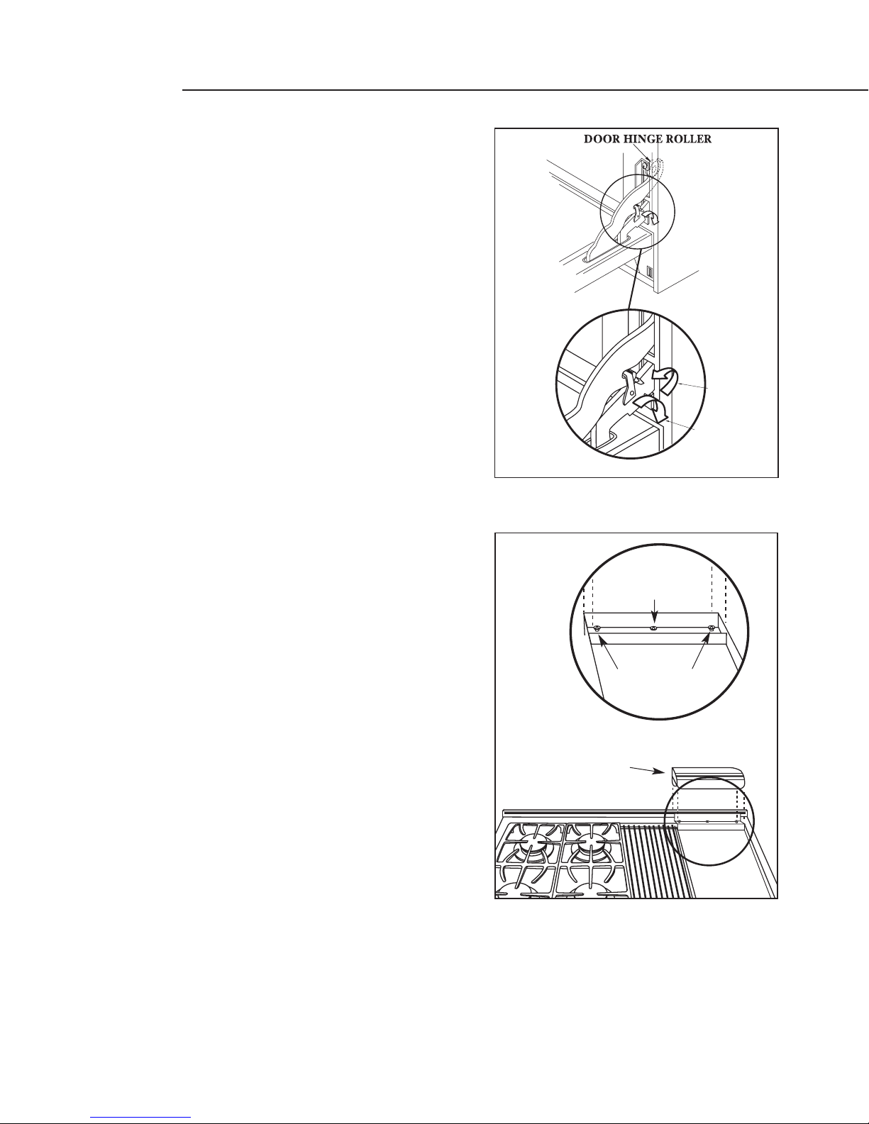
WOOD CONSTRUCTION:
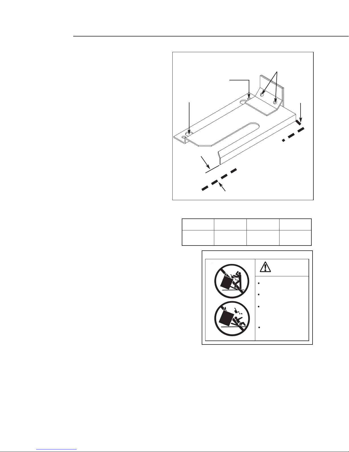
Place the bracket against the back wall,into the right
rear corner where the range is to be located. Leave a
gap between the wall (or side of range) and the
bracket (see fig. 6). Drill (2) 1/8”diameter pilot holes
in the center of the small holes. A nail or awl may be
used if a drill is not available. Fasten the bracket
securely to the floor and wall.
CONCRETE OR CEMENT CONSTRUCTION:
Hardware Required:
(2) sleeve anchors, lag bolts, and washers (not
provided). Locate the bracket as described above.
Drill the recommended size holes for the hardware.
Install the sleeve anchors into the holes and then install the lag bolts through the bracket. The bolts
must be properly tightened as recommended for the hardware. Fasten the bracket securely to the
floor and wall.
ONCE INSTALLED:
Complete the range installation per the instructions provided with the product. Check for proper
installation of the range and Anti-tip device by grasping the back of the unit and carefully attempt to
tilt the range forward.
A= 1/4”
Model
Series RDS-305
1/2”
RDS-48
5/8”
RDS-36
WARNING
ALL RANGES CAN TIP
INJURY COULD RESULT
INSTALL ANTI-TIP
BRACKET PACKED
INSIDE OVEN
SEE INSTRUCTIONS
Fig. 7
Fig. 6
(2) Large Holes for
Concrete Installations
(2)Small Holes for
Wood Installations
(2) Wood Screws into
Back Wall (ALL
Installations)
BACK
WALL
RIGHT SIDE OF
WALL OR RANGE
A

CABINET PREPARATION
10
STEP 3:
1) The range is a free standing unit. If the unit is to be placed adjacent to cabinets, the clearances
shown in fig. 8 (RDS-36 & 48) & fig. 9 (RDS-305) are required. The same clearances apply to island
installations.
2) The range can be placed in various positions with respect to the cabinet front, with the front either
flush or projecting, depending on the countertop depth.
3) The gas and electrical supply should be within the zones shown (fig. 8, 9, & 10).
4) The maximum depth of over head cabinets installed on either side of the hood is 13”.
5) Any openings in the wall behind the range and in the floor under the range must be sealed.
6) When there is less than a 12”clearance between combustible material and the back edge of the
range, (above the cooking surface) a DCS Low backguard or Full backguard must be installed, (fig.
11A ). When clearance to combustible material is over 12”no backguard is necessary (fig. 11B ).
These parts must be ordered separately. Fig. 11 indicate the space required for each type of
backguard.
7) Always keep the appliance area clear and free from combustible materials, gasoline and other
flammable vapors and liquids.
8) Do not obstruct the flow of combustion and ventilation air to the unit.
Min. 48" Wide Hood
Min. 36" Wide Hood
CAUTION:
36" Min. to
combustible
material ,
from cooking
surface
Electrical Supply
Gas Supply
35-3/8" Max. For Level Counter,
36-3/4" Max. With Range
Leveling Legs Fully Extended
12" Min. to combustible
material , each side
cooking surface
12"
3-1/4" 3-1/2"
BA
13"
Max.
A
18"Min.
As defined in the
“National Fuel Gas Code”
(ANSI Z223.1, Latest Edition).
The range height is adjustable. The level of the
range top must be at the same level or above the countertop level.
A
8" 16"
4" 12"
B
RDS 48 models
RDS 36 models
Fig. 8 RDS 36”/48” Models Only

CABINET PREPARATION
11
Min. 30" Wide Hood
(RDS 305 Models)
CAUTION:
36" Min. to
combustible
material ,
from cooking
surface
Electrical
Supply (RDS)
Gas Supply (RDS)
35-3/4" Max. For Level Counter,
37" Max. With Range
Leveling Legs Fully Extended
12" Min. to combustible
material , each side
cooking surface
9"
4" 1-1/2"
10-3/4" 2"
13"
Max
7"
18"Min.
As defined in the
“National Fuel Gas Code”
(ANSI Z223.1, Latest Edition).
The range height is adjustable. The level of the
range top must be at the same level or above the countertop level.
Fig. 10 All RDS Models
Electrical Supply
NEMA 14-50
Receptacle
2" Maximum
Protrusion from Wall
for Gas Supply
Gas Supply
Flex Line to Range
Manual Shut-Off
Valve must be
Easily Accessible
Fig. 9 RDS-305 Models Only

CABINET PREPARATION
12
0”Clearance
C
J
I
0”Clearance
B
A
F
C
H
E
D
G
36" Min.to
Combustibles
12" Min.to
Combustibles
without backguard
As defined in the
“National Fuel Gas Code”
(ANSI Z223.1, Latest Edition).
The range height is adjustable. The level of the
range top must be at the same level or above the countertop level.
Fig. 11 All RDS Models Product / Installation Clearance Specifications
A B C D E F G H I J K
RDS-48 Models 28-1/8”10-1/8”2”35-1/2”min.-37”max. 30-1/4”44-1/2”28-1/4”1-5/16”25”27-3/8”47-7/8”
RDS-36 Models 28-1/8”10-1/8”2”35-1/2”min.-37”max. 30-1/4”44-1/2”28-1/4”1-5/16”25”27-3/8”35-7/8”
RDS-305 Models 28-1/8”10-1/8”2”35-3/4”min.-37”max. 28-3/16”43-7/8”27-3/8”1-5/16”24-3/16”26-3/4”29-7/8”
STANDARD INSTALLATION: ISLAND INSTALLATION:
K
K
K
RDS-48 Models RDS-36 Models RDS-305 Models

BACKGUARD KITS:
The backguard is located as shown in Fig.
12. Secure the backguard to the wall
behind the range. Specific instructions for
installation of the full backguard or low
backguard can be found packaged
with the backguard. See also page 5,
“Planning The Installation”section.
A backguard must be installed when there
is less than a 12”clearance between
combustibles and the back of the range
(above the cooking surface). See fig. 11.
STEP 5:
ELECTRICAL CONNECTIONS
RDS-36 & 48 models
Always disconnect electric supply cord from the
wall outlet or service disconnect before servicing
this appliance. Observe all governing codes and
ordinances when grounding, in absence of
which, observe National Electrical Code ANSI /
NFPA No. 70-1990. The electrical supply must be
a 120/240 volt, 3 wire (plus ground) 60 Hz single
phase, 50 AMP circuit. The power receptacle
must be a NEMA 14-50 device to accept the four
prong plug supplied with the unit.The receptacle
should be located within the area shown in fig. 8,
page 10.
RDS-305 MODEL
The electrical supply must be a 120/240 volt, 3
wire (plus ground), 60 Hz, 30 AMP circuit. The
power receptacle must be a NEMA 14-50 device
to accept the four prong plug supplied with the unit.
The receptacle should be located within the area shown
in fig. 9, page 11.
BACKGUARD INSTALLATION
ELECTRICAL / GAS CONNECTIONS
13
Fig. 12
Wall Mount
Full Backguard
(Model #’s BGS-3030,
BGS-3036, BGS-3048)
Wall Mount
Low Backguard
(Model #’s BGS-1230,
BGS-1236, BGS-1248)
Electrical Supply
NEMA 14-50
Receptacle
Valve must be
Easily Accessible
m
from Wall
pply
Fig. 13
NEMA 14-50
Receptacle
Electrical Supply

ELECTRICAL / GAS CONNECTIONS
14
STEP 5: (CONTINUED)
RECOMMENDED GROUNDING METHOD
This appliance is factory equipped with a power supply cord with a four-prong grounding plug. It
must be plugged into a mating grounding,type receptacle,connected to a correctly polarized 120/240
volt circuit. If the circuit does not have a grounding type receptacle, it is the responsibility and
obligation of the installer to have the existing receptacle changed to a properly grounded and
polarized receptacle in accordance with all applicable local codes and ordinances by a qualified
electrician. In the absence of local codes and ordinances, the receptacle replacement shall be in
accordance with the National Electrical Code.
THE FOURTH PRONG (ROUND GROUNDING PIN) SHOULD NOT, UNDER ANY
CIRCUMSTANCES, BE CUT OR REMOVED.
GAS REQUIREMENTS
Verify the type of gas supplied to the location. The range is shipped from the factory set up and
adjusted for natural gas or L.P. gas as specified by the customer order. If the range is not compatible
with gas supply, return it to the dealer.
NATURAL GAS
Connection: 1/2”N.P.T. Minimum 5/8”dia. flex line. Pressure: 6”to 14”W.C.
LP GAS
Connection: 1/2”N.P.T. Minimum 5/8 dia. flex line. Pressure: 11”to 14”W.C.
A regulator is required at the LP source to provide a maximum of 14”W.C. to the range regulator.
STEP 6:
HOOK-UP
A manual valve must be installed external to the appliance,in an accessible location from the front for
the purpose of shutting off the gas supply. The supply line must not protrude beyond the back of the
unit. Make sure the gas supply is turned off at the wall valve before connecting the appliance.
The gas supply connections should be made by a qualified technician and in accordance with local
codes or ordinances. In the absence of a local code, the installation must conform to the National Fuel
Gas Code ANSI 223.1-1988, latest edition.
HOOK-UP TO GAS SUPPLY

STEP 6: (CONTINUED)
CAUTION:
The appliance must be isolated from the building’s gas supply piping system
by closing its individual manual shut-off valve during any pressure testing of
the gas supply piping system at test pressures equal to or less than 1/2 psig
(3.5kPa.). The appliance and its individual shut-off valve must be disconnected
from the gas supply piping system during any pressure testing of the system at
the test pressures in excess of 1/2 psig (3.5kPa.).” When checking the manifold
gas pressure, the inlet pressure to the regulator should be at least 7.0” W.C. for
natural gas or 12.0” for LP.
NOTE: The flex line for the gas supply must be metal and be approved by an approved
certifying agency (AGA, CGA, or UL). Never use a hose made of rubber or other
synthetic material, as the heat may cause the hose to melt and develop leaks.
When hooking up the gas supply from
range rear hard pipe to wall hard pipe,
installation length of flex line between
range/wall hard piping must
accommodate range being pulled
from wall for cleaning or servicing
purposes. When range is pulled from
wall, no strain should occur at range or
wall hard pipe connections (fig. 14).
HOOK-UP TO GAS SUPPLY
15
Fig. 14
Metal Flex Gas Line
Hard Pipe
1/2" NPT
Manual Shut-Off
Valve must be
Easily Accessible
WALL
Hard Pipe
Connection

TEST AND ADJUSTMENTS
16
STEP 7:
WARNING :
For Warranty coverage, DCS requires that burner adjustments be made by a
qualified technician at the time of installation. Extreme care should be used
when adjustments are made after installation. Improper or lack of
adjustments will void your warranty.
Note: No air shutter adjustment is possible on the top burners. This adjustment section
applies to the griddle and grill burners.
Check for the proper burner flame character-
istics and adjust air shutters if necessary (fig.
15). Each valve and air shutter is individually
tested and adjusted prior to shipment.
Normally adjustment is not required, however,
vibration during transit, gas conversion or
variations in the local gas supply may make
minor adjustments necessary. Burner flames
should be blue and stable with no yellow tips,
excessive noise or lifting of the flame from the
burner. If any of these conditions exist, check
that the air shutter or burner ports are not
blocked. If this condition persists, adjust the air
shutter as required. If the flame is too yellow,
indicating insufficient air, adjust the shutter
counterclockwise to increase air inlet. If the
flame is noisy or tends to lift away from the
burner, indicating too much air, turn the shutter
clockwise to reduce air. The griddle flames
should be 1-1/2" to 2". The grill burner flames
should be 3/8”to 5/8”(fig. 16).
If the top burner does not ignite, check the
spark igniter by listening for a clicking sound.
If you do not hear the igniter click,turn off the
burner. Check for a tripped circuit breaker,
blown fuse, or poor wire connection to the
igniter.
TO CLEAN EXTERIOR SURFACES
The stainless steel surfaces may be cleaned by wiping with a damp soapy cloth. Any mild glass cleaner
will remove fingerprints and smears. Do not use steel wool as it will scratch this surface. Small
scratches may be removed by lightly sanding, with the grain, using 120 grit paper.
1-1/2" - 2"
Typical Section of Proper Flame
3/8"- 5/8"
(Grill)
(Griddle)
Fig. 16
Typical Section of Proper Flame
Air Shutter
Griddle
1-1/2”- 2”3/8”- 5/8”
Grill
Fig. 15

INSTALLER FINAL CHECKLIST
17
GENERAL
Placement of unit.
Specified clearance maintained to cabinet surfaces.
Unit Level - front to back, side to side.
All packaging material and tie straps removed, drip pans clean and empty.
Backguard attached if there is less than 12" clearance above the cooking surface to combustibles
behind unit.
Radiant tray placed in grill unit (if equipped). The two grill racks in place.
ELECTRICAL
Receptacle with 50 ampere over-current protection is provided for service cord connection.
Adequate ground connection.
Front kick panel in place and two (2) screws secure.
GAS SUPPLY
Connection: 1/2 NPT with a minimum 5/8" diameter flex line. Site gas supply is compatible with
range model, & sufficient pressure is available (see gas requirements pg. 14).
The pressure regulator which is connected to the manifold is set for 5.0 W.C. for natural gas or
10.0 W.C. for LP.
Manual gas shut-off valve installed in an accessible location.
Unit tested and free of gas leaks.
OPERATION
All internal packing materials removed. Check below grate, pans and drip drawers.
If used on LP gas, verify that pressure regulator, orifice hoods, air shutters, and valve jets have been
set for use with LP gas.
Bezels centered on burner knobs and knobs turn freely.
Each burner lights satisfactorily, both individually and with other burners.
Flame adjustment for 3/8”soft blue cone made on ports of each top burner, low flame adjustment
verified.
Griddle is level and does not rock (not all models).
Drip trays are properly in place and pull out freely (Not all models).
Oven door hinges seated and door opens and closes properly.
Burner grates correctly positioned, level, and do not rock.

RDS-48 WIRING DIAGRAM
18
17468-01.eps Rev.A 08/02

RDS-48 SCHEMATIC
19
17468-02.eps Rev.A 08/02
Other manuals for RDS-305
2
This manual suits for next models
7
Table of contents
Other DCS Range manuals
Popular Range manuals by other brands

Samsung
Samsung NSG6D 8 Series installation manual

Lacanche
Lacanche RULLY General manual

Electrolux
Electrolux EI30GF55GS - 30 Inch Gas Range Guide d’utilisation et d’entretien

Frigidaire
Frigidaire FEF365CGBD Factory parts catalog

Samsung
Samsung NE63A6511SB user manual

Whirlpool
Whirlpool SF5140EY Use & care guide