DDS 2300CA Series User manual


SERIES 2300-CA
SLIDING DOOR OPERATORS
DETENTION DEVICE SYSTEMS
Detention Equipment Manufacturer - Detention Equipment Contractor - General Contractor
Contractors License CA # 606042 B1, C61/D28 + WA # DETENDS074C3 CC01
25545 Seaboard Lane, Hayward, California - USA Phone (510) 783-0771 Fax (510) 783-5409
INSTALLATIONINSTRUCTIONS
Refer to Approved Submittal Drawings for typical installation dimensions and locations.
Preparation - New Construction
The surface on which the DDS Sliding Door Operator is to be mounted should be free of excess mortar splatter, true to
architectural dimensions and flat in respect to the door opening. If the Architectural Plans and Specifications require embedded steel
plates for welding the DDS Sliding Door Operator in place, these embed plates are to be installed by the General Contractor prior
to installation of the DDS Sliding Door Operator and must all be in the same plane. The DDS Sliding Door Operator can be
bolted directly to the wall, but DDS recommends the use of embedded steel plates and welding these items securely to the wall. Any
items located within harms way of the installation should be protected from damage.
Preparation - Existing Construction (retrofit)
All ceilings, floors, walls and glass should be protected from any damage that could occur during the demolition of the existing
devices. Fans should be used to suck out all dust, smoke and fumes caused by demolition, preparation and installation of the new
DDS Sliding Door Operator. If existing embeds are able to be used for the new installation it will be noted on the Architectural
Plans and Specifications.
Layout
A. To determine the bottom height of the DDS Sliding Door Operator use the door opening height from the Architectural Door
Schedule.
1. Mark this height (above Finish Floor) at the Lock Pilaster Column side of the door opening, then use a precision
leveling device to transfer this height towards the open side by twice the door width, then snap a line between the
end marks (check this line for level).
B. For DDS Sliding Door Operator that are bolted to the wall (not welded)
1. To determine the bottom mounting holes height, snap a parallel line 3" above the bottom height line (check this line
for level).
2. To determine the top mounting holes height, snap a parallel line 10-1/2" above the bottom height line (check this line
for level).
3. To determine the center mounting hole locations
a. Determine the center-line of the Rear Lock Tube, then measure 4" from this center-line towards the open
side of the DDS Sliding Door Operator and make a vertical line between the two horizontal chalk lines.
4. To determine the left and right mounting hole locations
a. Measure the hole centers on the back of the DDS Sliding Door Operator then transfer them to the
appropriate side making a vertical line between the two horizontal chalk lines.
5. Use only high quality 1/2" or 5/8" concrete anchor bolts to fasten the DDS Sliding Door Operator to the wall. Make
sure the mounting holes are drilled accurately.
C. For DDS Sliding Door Operators that are bolted to the wall (top only) and welded at the bottom
1. To determine the top mounting hole height, snap a parallel line 10-1/2" above the bottom height line (check this line
for level).

SERIES 2300-CA
SLIDING DOOR OPERATORS
Page No. 2
2. To determine the center mounting hole locations
a. Determine the center-line of the Rear Lock Tube, then measure 4" from this center-line towards the open
side of the DDS Sliding Door Operator and mark on the horizontal chalk line.
3. To determine the left and right mounting hole locations
a. Measure the hole centers on the back of the DDS Sliding Door Operator then transfer them to the
appropriate side marking on the horizontal chalk line.
4. Use only high quality 1/2" or 5/8" concrete anchor bolts to fasten the DDS Sliding Door Operator to the wall. Make
sure the mounting holes are drilled accurately.
5. Make sure that the embeds installed by the General Contractor are in the same plane as the wall and are installed
per the Architectural Plans and Specifications.
Device Housing
A. Remove the Cover Screws open the Transom Cover to be able to remove the Transom Access Panel saving all the
hardware for re-installing.
B. Tack weld and/or fasten the Device Housing exactly as shown on this drawing, paying particular attention to the Device
Housing being level from left to right and front to back.
Lock Pilaster Column
A. Tack weld the Lock Pilaster Column in place exactly as shown on this drawing, paying particular attention to keeping the it
perpendicular and square to the transom.
Rear Lock Tube
A. Un-assemble the Rear Lock Tube.
B. Loosen the Device Backplate to allow the Lock Bar to be installed.
C. Slide the Rear Lock Tube assembled with the Lock Bar (top threaded tab facing towards the wall) up through the 1 1/4" X 1
1/2" rectangular hole located at the bottom of the Device Housing.
D. With the Lock Bar in place push the Rear Lock Tube up to the Device Housing, check that it is perpendicular to the transom
and tack weld in place paying particular attention not to get any weld splatter on the Lock Bar.
E. Assemble the Cover on the Rear Lock Tube
Wall Guide
A. Install the Wall Guide exactly as shown on the drawing holding the dimensions and it must remain parallel with the Device
Housing. Be sure not to burn through the Door Lock Tube while welding the Wall Guide as this will cause the Lock Bar to
not function properly.
Door Hanger and Guide
A. Install the Door Hanger and Bottom Door Guide on the door exactly as shown on the Approved Submittal Drawings. Pay
particular attention to the dimensions on the drawing as they must be welded true to the back plane of the door.

SERIES 2300-CA
SLIDING DOOR OPERATORS
Page No. 3
Finish Welding
A. Check all of the installed components for dimension accuracy
B. Weld in strict accordance with the Architectural Plans and Specifications
C. Clean all weld splatter, dress welds and touch up primer.
Locking Device
A. Make sure the Door Position Switch and Limit Switch are moved up as far as possible to avoid damage to the switches
during installation of the Carriage Assembly.
B. Install the Locking Device Assembly (make sure that the door numbers match) using the (4) Back Plate Bolts and (4) Back
Plate Washers.
Door Open Switch
A. Make sure the Limit Switch are moved up as far as possible to avoid damage to the switches during installation of the
Carriage Assembly.
B. Install the Door Open Switch Assembly as shown on the drawings using the screws supplied on the transom mount.
C. Run the wires through the "U" shaped switch mount on the back transom plate and secure them out of the way of any moving
parts.
Carriage Assembly
A. Remove the nylon tie straps that hold the Motor Mount Assembly for shipping, then back out the bolt that locks the Unlock
Master Bar and move the bar towards the side that the door closes. This will put the Pinion Gear out of the way.
B. Install the Carriage Assembly (make sure the door numbers match) as shown on the drawing.
Door
A. Install the door on the Carriage Assembly.
B. Snug the 1/2" nuts up on the Eccentric Door Hanger Bolts but not tight enough that you can not adjust the door.
C. Adjust the door so that it lines up with the Rear Lock Tube and the Eccentric Door Hanger Bolts are as close to center
height as possible. Now tighten the 1/2" nuts.
D. Make sure the Pinion Gear is still disengaged from the Rack using manual means then move the door open to closed a few
times to make sure there are no obstructions and the door travels freely with out binding.
Door Receiver
A. The notch at one end of the Door Receiver is to be placed at the bottom towards the back of the operator. Do not deviate from
the clearance dimensions at the top of the Door Receiver as this is required to clear the Access Cover.
B. Make sure that the door mates with the Door Receiver leaving equal space on both edges. Now tack the Door Receiver to
the Lock Pilaster Column. Open and close the door a few times to assure the proper fit, then finish welding per the
Architectural Plans and Specifications.

SERIES 2300-CA
SLIDING DOOR OPERATORS
Page No. 4
Pilaster Lock
A. Remove the Access Cover located on the front of the Vertical Lock Pilaster Column.
B. Install the Cleavis Mount supplied to your lock with the bolts supplied.
C. Attach the Cleavis Linkage supplied to the Pivot Assembly located in the transom above the Vertical Lock Pilaster
Column.
D. Now attach the Yoke Assembly to the Lock Cleavis Mount Assembly and bolt up the deadlock.
Final Adjustments
A. Check the adjustment of the door hanger so that the door travels freely throughout the entire travel.
1. Make sure that the door is adjusted parallel with the rear lock tube.
B. Next adjust the gear lash pressure by using the motor lock plate.
C. Next make sure that while applying a light drag to the door during travel that the Cam Follower stops approximately 1/8"
beyond the upper Dead Lock Bar.
1. If it doesn't stop correctly adjust the door travel limit switch to make it stop correctly.
D. Next adjust the door position in relation with the rear deadlock rod.
1. If the Dead Lock Bar is not properly seated with the Bottom Door Guide.
a. Loosen the door hanger bolts and by using a pole clamp move the door until the Dead Lock Bar just drops
into place, then move the door and additional 1/8" to assure that it is in the center of the slot on the Door
Bottom Guide.
E. Adjust the Cleavis Linkage with the deadlock in the up position so that the Pivot hole at the Yoke is positioned 5/16" above
the centerline of the Pivot Bolt.
F. Move the Unlock Master Bar to the door opened side as far as possible.
G. Now attach the Pivot to Master Bar Linkage to the Pivot Assembly.
1. Then adjust the Yoke Assembly and attach the Unlock Master Bar, this should slip on freely without moving either
part.
2. Try the Paracentric Lock a few times making sure the motor and dead lock release freely .
H. Install the Transom Access Panel with the Transom Access Panel Bolt & Nut supplied.
I. Adjust the Limit Switch so that it just makes contact (audible click) when the Lift Pivot is in the full deadlock position.
J. Adjust the Motor Cutoff Limit Switch so that it just makes contact (audible click) when the Unlock Master Bar touches it. Be
sure that the switch lever is not touching the switch body.
K. Electrical Hookup
1. Refer to the Wiring Diagram on the next page for the factory wiring of the limit switches and motor.
2. Secure all lines at completion to the Access Cover with the nylon wire ties supplied.
3. Try the door a few times under power until you are satisfied with the operation.
L. Adjust the Solid State Motor Controller for the proper closer pressure
M. Secure the device by using the Cover Screws supplied to securely fasten the Housing Cover to the transom.

SERIES 2300-CA
SLIDING DOOR OPERATORS
Page No. 5
Special Components
A. See Approved Submittal for drawings and instructions
Special Electrical Components
A. See Approved Submittal for drawings and instructions
The wiring hook up is referenced in the Approved Submittal Drawings.

SERIES 2300-CA
SLIDING DOOR OPERATORS
Page No. 6
SPECIFICATIONS
Series 2300CA Rack & Pinion Drive Corridor Device
A. Entry and Vestibule Door Operation Device – Door weight not to exceed 400 lbs
1. Housing unit entry and vestibule doors for Level III and Administrative Segregation Housing Units shall have fully
automatic sliding doors with functions and components as follows:
a. Unlock, open and lock open by electric switch, a 36 inch wide door in not more than eight seconds.
b. Unlock, close and deadlock closed, by electric switch, a 36 inch door in not more that eight seconds.
c. Stop the movement of any door in mid-travel, leaving the door fixed at that point, so that it cannot be
moved by hand in either direction until mechanically released with the paracentric key at the door lock
pilaster or reactivated electrically.
d. Instantly reverse the direction of movement of any individual door.
e. When a door is blocked and blocking object is removed, the door automatically continues movement to the
open or closed position if switch is still depressed.
f. Sally port or vestibule doors shall be interlocked so that only one door can be opened at a time using
electric controls. Interlocking circuit shall be provided at Control Console under provisions of Division 17.
g. Force exerted by the door in travel shall be 40 to 45 lbs., adjustable Solid State Motor Controller.
h. Each door automatically deadlocks closed at two concealed points at the rear of the door; at bottom and
top of lockbar. The locking means is completely concealed and there are no openings in the pilaster or
lugs projecting from the edge of the door.
i. Individual doors may be unlocked mechanically and may be operated electrically from both sides of the
door by the same paracentric key..
g. Each door has a limit switch at each end of travel, an additional switch monitors the position of the lockbar.
The switches indicate three conditions – closed and locked, open and locked, and in-travel.
k. The Door Operator is capable of adjustment within the transom.
2. Components
a. Motor is 1/10 horsepower, single phase, 120V, 60 Hertz, U.L. listed manufactured by Reliance Electric.
Motor draws no more than 1.5A under full load current.
b. Hanger Guides: 3/16 inch thick steel plate; minimum width 75 percent of door width.
c. Hanger to interlock with track support with a clearance of not more than ¼ inch.
d. Hanger Support Roller: Turned from solid steel, 2-3/4 inch O.D. grooved 3/8 inch deep to engage 5/8”
diameter steel track.
e. Rollers shall have anti-friction ball bearings with hardened members and grease shield on both sides.
f. Roller Studs and Eccentric Adjusters: High alloy steel, heat treated and a self-locking nut.
g. Provide heavy duty rubber bumpers, minimum 2 inch round x ¾ in deep, to quiet and cushion the door at
each end of travel.
h. Paint entire inside of housing assembly, except track, rollers and drive mechanism with rust inhibiting
primer.

SERIES 2300-CA
SLIDING DOOR OPERATORS
Page No. 7
OPERATING DEVICE TRANSOMS, COVERS AND ACCESSORIES
A. Transoms:
1. Transom backplate is factory punched for six anchor bolts.
2. Horizontal transoms is constructed of 3/16 inch thick steel plate.
3. Transoms shall be rectangular or sloped as indicated. Mezzanine level transoms shall be sloped 26 degrees
minimum.
4. Provide 10 gage steel battens for joining transoms.
5. All openings in transoms are baffled, including bottom slot for hanger to prevent wires or contraband from entering
the transom.
6. A wire tray is provided inside the transom.
7. Fasteners are pinned “Allen” head socket fasteners under provisions of Section 05051
8. Transoms for exterior applications shall be weathertight.
B. Transom Covers:
1. Transom covers are 10 gage steel plate.
2. Covers are secured in place with security screws, hinged and locked to the transom.
C. Vertical Lock Bar Cover:
1. Fabricated from of 3/16" steel plate.
2. The vertical lock bar cover is removable only when the transom cover is opened.
D. Door and Wall Guides:
1. Fabricated from 3/16 inch thick stainless steel.
2. The guides overlap a minimum of one inch vertically and five inches horizontally when the door is in the closed
position
3. There is a minimum of 5/8 inch contact between lock bar and door guide.
4. Clearance between lock bar and guides is 1/16 inch on either side.
E. Receiver:
1. Receiver is one inch deep inside dimension, with ¾ inch engagement.
ELECTRICAL WORK
A. Internal wiring and final connections within the transom of sliding door devices. Wire to terminal block of each door, ready for
wiring and final connections by Divison 16 and 17 as indicated below.
FABRICATION - GENERAL
A. Factory assemble items where practicable, true to line and free of distortion of defects.
B. Welding
1. Steel and stainless steel components not plant fabricated shall be designed for field-welded connections.
2. Plug or stitch welds unless otherwise indicated.

SERIES 2300-CA
SLIDING DOOR OPERATORS
Page No. 8
3. Weld according to American Welding Society standards.
4. Remove excess welding slag, burrs and rough edges.
5. Prime bare welds using job specified primer.
C. Equipment to be installed under Bid Pack 3 shall be fully fabricated, assembled and finished, ready for final installation and as
follows:
1. Work, including wiring, within transoms and emergency release cabinets for sliding doors shall be completed at the
factory.
2. Hardware that is essentially non-projecting shall be installed in doors and frames, at the factory, including the
following:
a. Mechanical locks and their associated strikes, keepers and escutcheons.
b. Hinges, either screwed or welded, shall be fastened to the doors.
c. Flush pulls.
3. Other hardware shall be field installed; including electric locks, closers, position indicators, pulls, cylinder shields,
door hangers and guides, door bottoms and weather protection, projecting angle clips for cell door boots and gun
ports in Control Room hollow metal frames.
4. The field installed hardware group for each opening shall be separately packaged, accompanying the doors and
clearly identified with its opening.

SERIES 2300-CA
SLIDING DOOR OPERATORS
Page No. 9
PRODUCTWARRANTY
Warranty - Standard Products
DETENTION DEVICE SYSTEMS (DDS) warrants each standard product manufactured and sold by it to be free of defects in
materials and workmanship for such period of time and under such conditions as are specified herein or as may be specified by DDS
on the face of its quotation or otherwise reduced to writing and expressly approved by DDS. The warranty period so specified by
DDS shall commence on the date of shipment from DDS to the original purchaser. If no period of time is stated, then DDS's Warranty
for Standard Products is limited to one (1) year from the date of delivery.
Repair or at DDS's option, replacement of defective parts shall be the sole and exclusive remedy under warranty, provided that, DDS
may, as an alternative, elect to refund an equitable portion of the purchase price of the Product, items expendable in normal use are
not covered by this warranty. All warranty replacement or repair of parts shall be limited to Product malfunctions which, in the sole
opinion of DDS, are due or traceable to defects in original materials or workmanship. All obligations of DDS under this warranty shall
cease in the event of abuse, accident, alteration, misuse or neglect of the Product. In-warranty repaired or replacement parts are
warranted only for the remaining unexpired portion of the original warranty period applicable to the repaired or replaced parts. After
expiration of the applicable warranty period, Buyer shall be charged at the then current prices for parts, labor, and transportation.
Reasonable care must be used to avoid hazards. DDS expressly disclaims responsibility for loss or damage caused by use of its
Products other than in accordance with proper operation procedures.
No warranty is provided by DDS for products sold hereunder which are not manufactured by DDS, but the manufacturer's warranty
for such products, if any, shall be assigned to the Buyer without recourse to DDS.
THIS WARRANTY IS EXPRESSLY IN LIEU OF AND EXCLUDES ALL OTHER EXPRESSED OR IMPLIED WARRANTIES,
INCLUDING BUT NOT LIMITED TO WARRANTIES OF MERCHANT ABILITY AND OF FITNESS FOR PARTICULAR PURPOSE,
USE, OR APPLICATION, AND ALL OTHER OBLIGATIONS OR LIABILITIES ON THE PART OF DDS, UNLESS SUCH OTHER
WARRANTIES, OBLIGATIONS OR LIABILITIES ARE EXPRESSLY AGREED TO IN WRITING BY DDS.
Warranty - Expendable Products
DDS warrants that at the time of delivery expendable items or Products manufactured and sold by it hereunder are free of defects in
material and workmanship and conform with DDS's specifications or other specifications expressly agreed to in writing by DDS, BUT
DDS SHALL HAVE NO OTHER OR FURTHER RESPONSIBILITY THEREFORE, WHATSOEVER, AND DDS DISCLAIMS
IMPLIED WARRANTIES OF MERCHANT ABILITY AND FITNESS WITH RESPECT THERETO.
Authorized By _____________________________ Date ____________
SERIES 2300-CA
SLIDING DOOR OPERATORS
Page No. 10
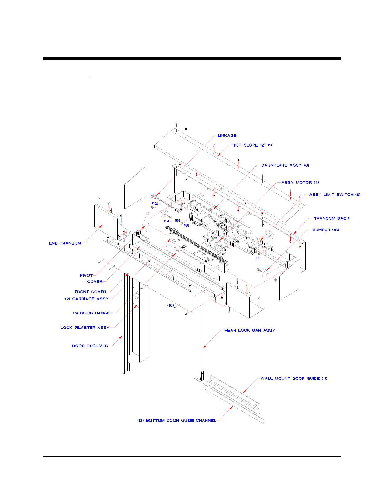
PARTSLISTS
Note: When order parts for the following items, always refer first to the Door Number and the appropriate Part No.’s on the Bill of
Materials. Some of the parts are sold as assembled items only.
Series 2300CA General Assembly (LH as shown, RH opposite)
SERIES 2300-CA
SLIDING DOOR OPERATORS
Page No. 11
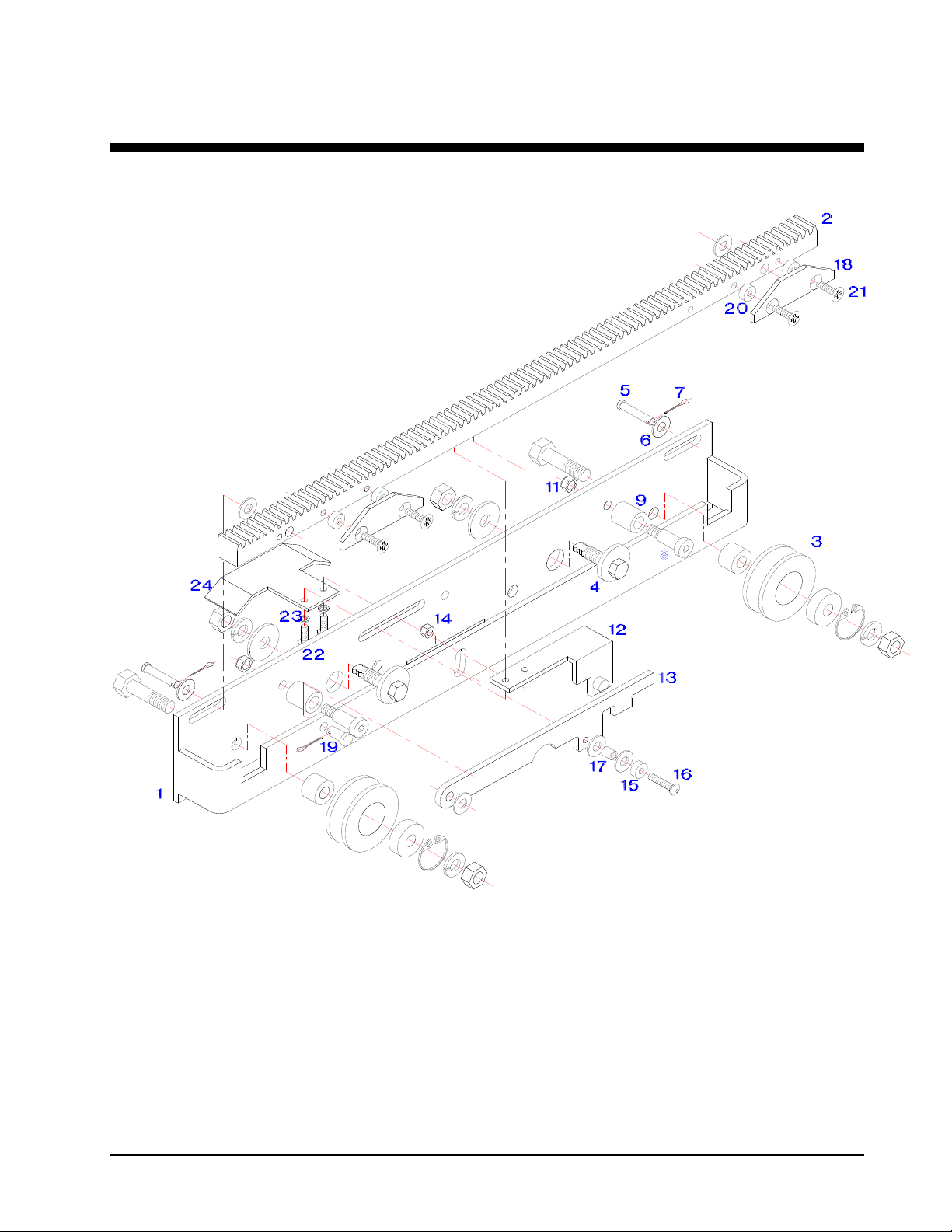
Carriage Assembly (LH as shown, RH opposite)
SERIES 2300-CA
SLIDING DOOR OPERATORS
Page No. 12
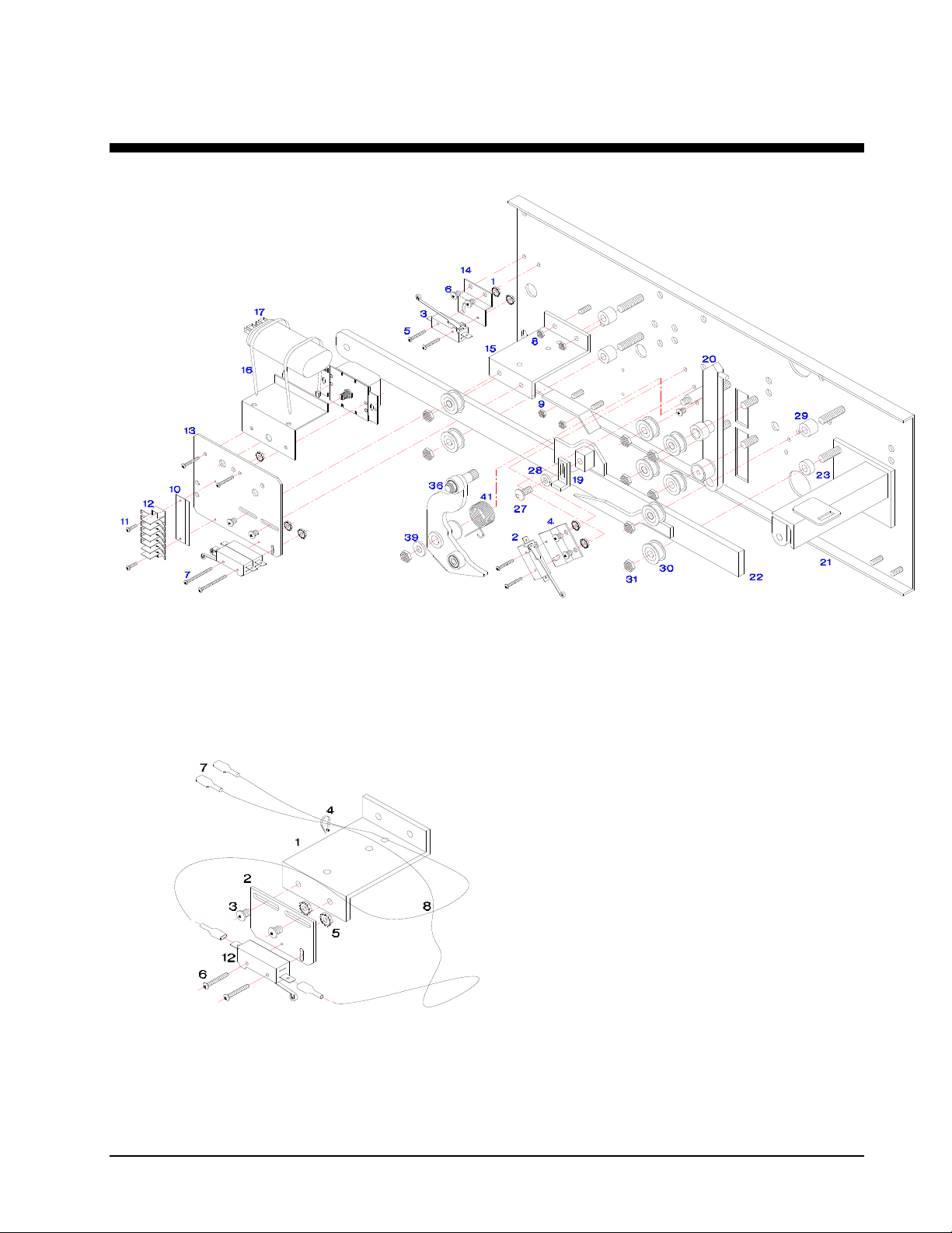
Locking Device Assembly (LH as shown, RH opposite)
Door Open Switch Assembly (LH as shown, RH opposite)

SERIES 2300-CA
SLIDING DOOR OPERATORS
Page No. 13
ADDITIONALCONDITIONS
Maintenance - Every 12 Months
Check for loose bolts
Check wires for tightness and make sure they are not interfering with any moving parts
Check for abnormal wheel wear
Clean out any debris buildup
Adjustments - Non Factory
All adjustments to the device are to be made by Certified Factory Technicians only, any adjustments by un-authorized personnel
will Void Warranty.
FACTORYINFORMATION
Location
Detention Device Systems
25545 Seaboard Lane
Hayward, California 94545
Hours
8:00 AM to 4:30 PM Monday thru Friday except Holidays
Plant Closure from Christmas Eve thru the 1st working day after New Years
Phones
(510) 783-0771
FAX (510) 783-5409 and (510) 785-4379

SERIES 2300-CA
SLIDING DOOR OPERATORS
Page No. 14
TABLEOFCONTENTS
INSTALLATION INSTRUCTIONS...............................................................................................................................1
Preparation - New Construction...................................................................................................................1
Preparation - Existing Construction (retrofit)................................................................................................1
Layout..........................................................................................................................................................1
Device Housing............................................................................................................................................2
Lock Pilaster Column...................................................................................................................................2
Rear Lock Tube............................................................................................................................................2
Wall Guide....................................................................................................................................................2
Door Hanger and Guide...............................................................................................................................2
Finish Welding..............................................................................................................................................3
Locking Device.............................................................................................................................................3
Door Open Switch........................................................................................................................................3
Carriage Assembly.......................................................................................................................................3
Door.............................................................................................................................................................3
Door Receiver..............................................................................................................................................3
Pilaster Lock.................................................................................................................................................4
Final Adjustments.........................................................................................................................................4
Special Components....................................................................................................................................5
Special Electrical Components ....................................................................................................................5
SPECIFICATIONS.......................................................................................................................................................6
Series 2300CA Rack & Pinion Corridor Device ...........................................................................................6
Operating Device Transoms, Covers and Accessories................................................................................7
Electrical Work.............................................................................................................................................7
Fabrication - General...................................................................................................................................7
PRODUCT WARRANTY .............................................................................................................................................9
Warranty - Standard Products......................................................................................................................9
Warranty - Expendable Products.................................................................................................................9
PARTS LISTS..............................................................................................................................................................10
Series 2300CA General Assembly (LH as shown, RH opposite).................................................................10
Carriage Assembly (LH as shown, RH opposite)........................................................................................11
Locking Device Assembly (LH as shown, RH opposite).............................................................................12
Door Open Switch Assembly (LH as shown, RH opposite)........................................................................12
ADDITIONAL CONDITIONS........................................................................................................................................13

SERIES 2300-CA
SLIDING DOOR OPERATORS
Page No. 15
Maintenance - Every 12 Months..................................................................................................................13
Adjustments - Non Factory...........................................................................................................................13
FACTORY INFORMATION .........................................................................................................................................13
Location........................................................................................................................................................13
Hours............................................................................................................................................................13
Phones.........................................................................................................................................................13
TABLE OF CONTENTS...............................................................................................................................................14
BILL OF MATERIALS.................................................................................................................................................16
Table of contents
Popular Door Opening System manuals by other brands


Dormakaba
Dormakaba PORTEO Mounting instructions

CornellCookson
CornellCookson FS-500EP Series Installation instructions and operation manual

GEZE
GEZE ECturn Inside Installation and service instructions

LCN
LCN 4050 Track Series installation instructions

ONLEVEL
ONLEVEL Banana Slide 50 installation instructions

Chamberlain
Chamberlain K1A6636 quick start guide

Carlisle Brass
Carlisle Brass CDG003 installation instructions

D+H
D+H KA 66-TW1-K-BSY+ Original instructions

Assa Abloy
Assa Abloy NORTON RIXSON 6300 Series installation instructions

GAL
GAL MOVFE 2500 MECHANICAL MANUAL

Assa Abloy
Assa Abloy SARGENT 281 Series installation instructions

Yale
Yale UNOplus 3000 quick start guide