ddtop UQK-400 User manual

1/ 10
WWW.DDTOP.COM
UQK-400
FLOAT LEVEL SWITCH
Operation Manual
UQK-400-DT-JS-1019-2018(A)

2/ 10
WWW.DDTOP.COM
Preface
Thank you for choosing the products of Dandong Top Electronics Instrument (Group) Co., Ltd.
This operation manual provides you with important information on installation, connection and
commissioning as well as on maintenance, troubleshooting and storage. Please read it carefully
before installation and commissioning and keep it as part of the product near the meter for easy
reading.
This manual can be downloaded by entering the version number at www.ddtop.com .
If the instructions are not followed, the protection provided by the meter may be destroyed.
Trademark, Copyright and Restriction Instructions
Dandong Top Electronics Instrument (Group) Co.,Ltd.®, Dandong Top Pump Co., Ltd.®, DDTOP®
are registered trademarks of the company.
he performance specifications of the meter are effective as of the date of publication and are
subject to change without notice. Dandong Top Electronics Instrument (Group)Co.,Ltd. reserves the
right to modify the products described in this manual at any time without prior notice.
Quality Assurance
Dandong Top Electronics Instrument (Group) Co.,Ltd. guarantees that all glass plate level gauge
have no defects in materials and manufacturing processes within one year from the date of delivery.
During the warranty period, if the product returns with quality problems and the claim is
determined by the manufacturer to be within the scope of warranty, Dandong Top Electronics
Instrument (Group) Co.,Ltd. is responsible for repair or replacement of the buyer (or owner) free of
charge.
Dandong Top Electronics Instrument (Group) Co.,Ltd. is not responsible for the costs caused by
improper use of equipment, labor claims, direct or subsequent damage and installation and use of
equipment. In addition to the special written warranty certificate for certain products of Dandong
Top Electronics Instrument (Group) Co.,Ltd., Dandong Top Electronics Instrument (Group) Co.,Ltd.
does not provide any express or implied warranty.
Quality
Dandong Top Electronics Instrument (Group) Co.,Ltd. has passed the ISO9001 quality system
certification. The whole process of product production is strictly in accordance with the scope of the
quality system, providing the strongest guarantee for product and service quality.

3/ 10
WWW.DDTOP.COM
Contents
1. Safety Tips ...................................................................................................................................................................... 4
1.1 Explosion May Result In Death or Serious Injury. ...................................................................................... 4
1.2 Process Leaks Can Cause Serious Injury or Death..................................................................................... 4
1.3 Failure to Follow Safe Installation Guidelines May Result In Death or Serious Injury.................... 4
2. Product Manual............................................................................................................................................................ 4
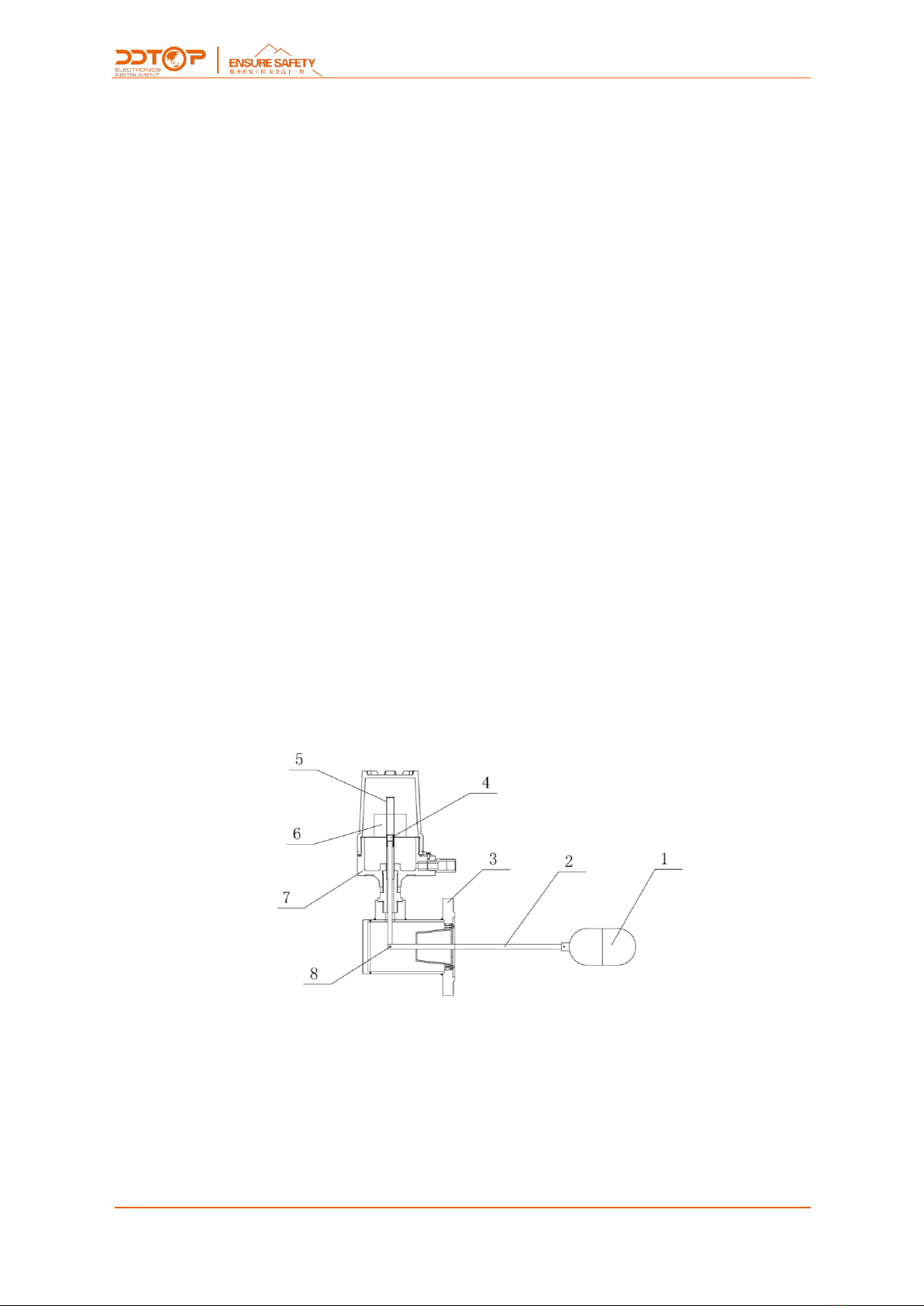
2.1 Main Structure of Product -Figure 1.............................................................................................................. 4
2.2 Operating Principle –Figure2............................................................................................................................ 5
2.3 Packing..................................................................................................................................................................... 5
2.4 Transporting........................................................................................................................................................... 5
2.5 Warehousing.......................................................................................................................................................... 5
3. Technical Characteristics............................................................................................................................................ 5
3.1 Main Performance................................................................................................................................................ 5
3.2 Main Parameters................................................................................................................................................... 5
4. Dimensional Schematic -Figure 2.......................................................................................................................... 6
5. Unpacking and Inspection ........................................................................................................................................ 6
5.1 Unpacking Inspection Notice ........................................................................................................................... 6
5.2 Check Content....................................................................................................................................................... 6
6 Installation ....................................................................................................................................................................... 7
6.1 Installation Tool..................................................................................................................................................... 7
6.2 Installation Technical Requirements............................................................................................................... 7
c6.3 Installation Process............................................................................................................................................. 7
7. Debugging ..................................................................................................................................................................... 7
7.1 Preparation for Commissioning....................................................................................................................... 7
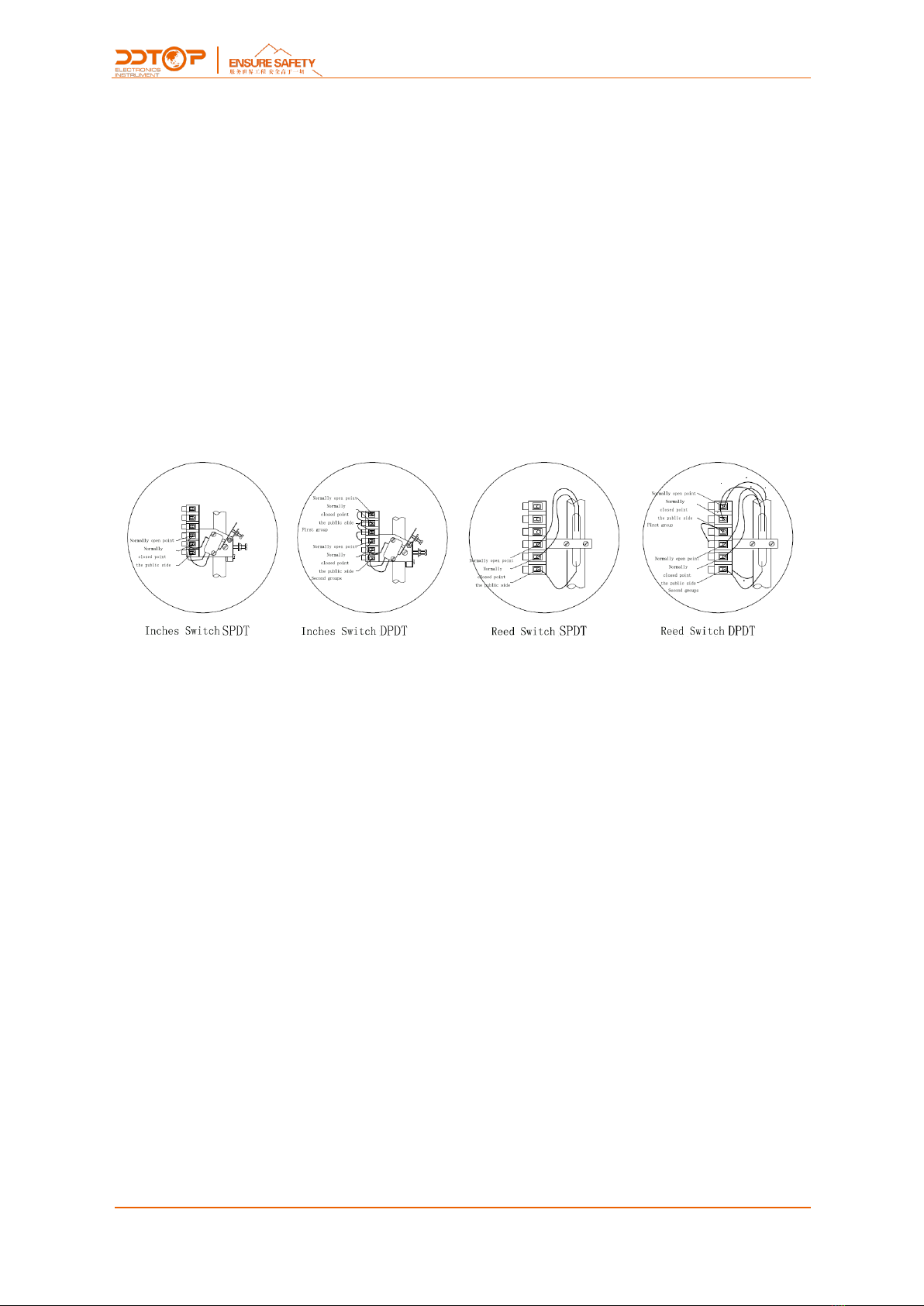
7.2 Electrical Wiring..................................................................................................................................................... 7
7.3 Debugging Operation Process......................................................................................................................... 8
8 Precautions...................................................................................................................................................................... 8
9 Fault Analysis and Elimination .................................................................................................................................. 9
10.Disassembly .................................................................................................................................................................. 9
10.1 Warning................................................................................................................................................................. 9
10.2 Waste Removal ................................................................................................................................................... 9
11 Product Certification.................................................................................................................................................. 9

4/ 10
WWW.DDTOP.COM
1. Safety Tips
It is expressly prohibited to modify or change products for safety reasons,repair or replacement
only allows the use of accessories specified by the manufacturer.
1.1 Explosion May Result In Death or Serious Injury.
When installing equipment in an explosive atmosphere, be sure to follow applicable local, national,
international standards, codes, and procedures. Be sure to install the equipment in Intrinsically safe
or non-flammable site operating procedures.
1.2 Process Leaks Can Cause Serious Injury or Death.
Care should be taken to lift the transmitter. If the process seal is damaged, the medium may leak at
the joint.
1.3 Failure to Follow Safe Installation Guidelines May Result In Death or Serious Injury.
The operations described in this manual are performed by professionally trained and qualified
professionals or end-user specialized professionals to complete.
2. Product Manual
2.1 Main Structure of Product -Figure 1
Figure1
1. Float, buoyancy measuring element
2. Connecting rod, swinging with the float
3. Flange

5/ 10
WWW.DDTOP.COM
4. Magnetic rod, including magnetic steel
5. Isolation set
6. Magnetic switch assembly, micro switch and reed switch optional
7. Cage, 360° rotation
8. Hinge
2.2 Operating Principle –Figure2
The float is rigidly connected to the connecting rod, and the connecting rod and the magnetic rod
are connected by a hinge. When there is no level or the level is not at the set alarm position, the
floating ball drives the connecting rod to swing downward under the action of its own weight, so
that the magnetic rod at the end of the connecting rod moves in the opposite direction and enters
the magnetic field region of the magnetic switch assembly. By magnetic induction or by magnetic
enthalpy, the magnetic switch or the bias magnet is attracted to make the switch contact open or
close. When the level rises, the float drives the connecting rod to swing upward under the action of
buoyancy, so that the magnetic rod at the end of the connecting rod moves downward in the
opposite direction, the magnetic rod is separated from the magnetic field of the magnetic switch
assembly, and the magnetic control switch returns to the original state or under the action of
self-weight, the biased magnetic steel returns to a new equilibrium position, so that the switch
contacts are turned on or off, and the level control and alarm are realized.
2.3 Packing
Please send the packaging waste to a special recycling agency.
2.4 Transporting
When hoisting and transporting, please select qualified hoisting equipment and lifting straps, and
pay attention to safety.
2.5 Warehousing
Storage Temperature -20℃~40℃;Storage Humidity≤40%.
3. Technical Characteristics
3.1 Main Performance
3.1.1 Has Passed the National Explosion-Proof Certification, Certification Mark:
Intrinsically safe type Ex iaⅡCT5/T6 Ga
Explosion isolation type Ex dⅡCT1~T5/T6 Gb
3.1.2 Product Performance Standards: Q/AMM003 Float Level Switch
3.2 Main Parameters
3.2.1 Power Supply Voltage:AC220V DC24V

6/ 10
WWW.DDTOP.COM
3.2.2 Output Signal: Relay Contact SPDT or DPDT
4. Dimensional Schematic -Figure 2
If the order is required to be a special size, the actual size will prevail.
Figure 2
5. Unpacking and Inspection
5.1 Unpacking Inspection Notice
5.1.1 Check whether the product nameplate (Figure 4) is consistent with the supply list information.
Figure4 Sample Nameplate
5.1.2 对照装箱清单,检查各零件数量,材质是否正确。
5.1.2 Check the quantity of each part against the packing list and the material is correct.
5.2 Check Content

7/ 10
WWW.DDTOP.COM
5.2.1 Check the appearance of the instrument for defects, damage and other abnormal conditions.
6 Installation
6.1 Installation Tool
6.1.1 Wrench, flange gasket and flange bolts for process connections.
6.1.2 Level
6.2 Installation Technical Requirements
6.2.1 Ensure that the lead length and inner diameter of the equipment are suitable for the selected
float level controller to ensure that the float is in the tank.
6.2.2 Ensure that the horizontal level of the equipment is within 3 °.
6.2.3 Ensure that no ferromagnetic particles in the medium may be attracted to the controller's
magnetic steel rod to affect the switching performance.
6.2.4 The liquid surface fluctuation frequency of the measured medium shall not be too large, and
the fluctuation range shall not exceed the allowable action limit.
6.3 Installation Process
6.3.1 Place the gasket on the sealing surface of the container flange.
6.3.2 Carefully pick up the controller and load the float into the container.
6.3.3 Align the controller flange with the container flange, and install the head to ensure that the
float swings up and down instead of swinging left and right.
6.3.4 Install flange bolts and nuts. Tighten the flange bolts alternately to ensure that the flange
gaskets are installed correctly.
7. Debugging
7.1 Preparation for Commissioning
7.1.1 Debugging Tools: Multimeter
7.2 Electrical Wiring
7.2.1 Cable preparation: Wiring should be OD10mm five-core rubber sleeve flexible cable or rubber

8/ 10
WWW.DDTOP.COM
cable, one core is internal grounding wire, and the other four cores are connected to a pair of
normally open and normally closed contacts (using two of them) Core), or for two pairs of normally
open, normally closed contact wiring.
7.2.2 Electrical wiring
1. Remove the cover
2. According to the wiring diagram wiring, please note that the high-level and low-reporting
switches are reversed. Be sure to connect to the correct terminal according to the wiring diagram
(see Figure 4). For the SPDT form, the high-order report is connected to a pair of normally closed
points - the common end, and the low-end is connected to a pair of normally open points - the
common end; for the DTDP form, the high report is connected to two pairs of normally closed
points - the common end, and the low report is connected to the two pairs. Opening point - public
end.
Figure 4 Electrical Wiring
※The normally open and normally closed points in the wiring diagram refer to the
original state of the micro switch or reed switch.
3. All terminals should be in good contact, the output nut should be properly pressed to prevent the
lead from loosening.
4. Ensure that excess wires do not interfere with the movement of the switch cover or switch
mechanism.
7.3 Debugging Operation Process
7.3.1 Before installation, connect the multimeter to the terminal that needs wiring. Simulate the
level lift and raise or lower the float by hand to verify that the output status is correct.
7.3.2 After installation, connect the multimeter to the terminal that needs wiring. When the
level reaches the alarm position, check whether the level output is correct.
8 Precautions
8.1 The density of use should be the same as the design density. If the density changes, please
inform the factory;

9/ 10
WWW.DDTOP.COM
8.2 Make sure the power supply is safe and reliable, and must be powered off before opening the
cover.
8.3 When the vibration is large, it is not suitable to use the float level controller.
8.4 Medium with viscosity ≥500mPa/s is not suitable for use with float level controller.
8.5 Medium with ferromagnetic particles is not suitable for use with float level controller.
8.6 After wiring, tighten the power supply cover to prevent the instrument from getting wet.
9 Fault Analysis and Elimination
Fault Phenomenon
Cause of Issue
Troubleshooting Method
The level to the specified
position switch does not
work.
1. The ball is too heavy to float.
2. Float ball, leak, and medium.
3. The installation location is wrong.
4. The lead pipe is too long, the float is
stuck in the lead pipe and does not
reach into the tank.
5. Ferromagnetic particles or obstacles in
the medium cause the float ball to
block.
6. Magnetic switch assembly failure.
1. Confirm the density or replace the float.
2. Replace the float.
3. Confirm the installation position according to the
instructions to ensure that the head is flushed.
4. Confirm that the order neck is larger than the
length of the guide tube. If the neck is small,
contact the factory to replace the relevant parts.
5. Remove the instrument to clean the float ball and
magnetic rod.
6. Replace the switch assembly.
10.Disassembly
10.1 Warning
Attention should be paid to hazardous process conditions, such as pressure inside the vessel, high
temperatures, corrosive or toxic medium, etc.
Refer to the instructions in section 6.3 Installation Operation and Section 7.2 Electrical Wiring to
remove the parts in the reverse order of operation.
10.2 Waste Removal
Waste disposal should be carried out in accordance with the current guidelines in each region.
11 Product Certification

10 / 10
WWW.DDTOP.COM
Table of contents
Other ddtop Switch manuals
Popular Switch manuals by other brands

Belden
Belden grass valley SIRIUS 800 Series Operating System Upgrade Manual

Panasonic
Panasonic WJ420 - MIXER operating instructions

FS
FS STP Series Configuration guide

EUCHNER
EUCHNER ES-A-C5H-EX Safety Information and Maintenance

EtherWAN
EtherWAN EX33000 Series installation guide

Rose electronics
Rose electronics Vista Mini Installation and operation manual