De Nora Capital Controls 71V3B Series User manual

- 1 - 115.6031.0
Instruction Manual
Series 71V3B
Electrically Heated Vaporizer
CAPITAL CONTROLS®

115.6031.0 - 2 -
These instructions describe the installation, operation and maintenance of the subject equipment. Failure to
strictly follow these instructions can lead to an equipment rupture that may cause signicant property damage,
severe personal injury and even death. If you do not understand these instructions, please call De Nora Water
Technologies for clarication before commencing any work at +1 215-997-4000 and ask for a Field Service Manager.
De Nora Water Technologies reserves the rights to make engineering renements that may not be described herein. It is the
responsibility of the installer to contact De Nora Water Technologies for information that cannot be answered specically by
these instructions.
Any customer request to alter or reduce the design safeguards incorporated into De Nora Water Technologies equipment
is conditioned on the customer absolving De Nora Water Technologies from any consequences of such a decision.
De Nora Water Technologies has developed the recommended installation, operating and maintenance
procedures with careful attention to safety. In addition to instruction/operating manuals, all instructions given on
labels or attached tags should be followed. Regardless of these eorts, it is not possible to eliminate all hazards from the
equipment or foresee every possible hazard that may occur. It is the responsibility of the installer to ensure that the recom-
mended installation instructions are followed. It is the responsibility of the user to ensure that the
recommended operating and maintenance instructions are followed. De Nora Water Technologies cannot be
responsible deviations from the recommended instructions that may result in a hazardous or unsafe condition.
De Nora Water Technologies cannot be responsible for the overall system design of which our equipment may be an
integral part of or any unauthorized modications to the equipment made by any party other that De Nora Water
Technologies.
De Nora Water Technologies takes all reasonable precautions in packaging the equipment to prevent shipping damage.
Carefully inspect each item and report damages immediately to the shipping agent involved for equipment shipped“F.O.B.
Colmar” or to De Nora Water Technologies for equipment shipped “F.O.B Jobsite”. Do not install damaged equipment.
De Nora Water Technologies, Colmar Operations
Colmar, Pennsylvania, USA
is ISO 9001: 2008 Certied

- 3 - 115.6031.0
Table of Contents
SAFETY SUMMARY........................................................................................................................................................... 5
READ FIRST ....................................................................................................................................................................... 6
1 INTRODUCTION ................................................................................................................................................................ 7
1.1 General Description ....................................................................................................................................................................................7
1.2 Model Numbering Breakdown ...............................................................................................................................................................8
1.3 Component Description......................................................................................................................................................................... 10
1.3.1 General...................................................................................................................................................................................... 10
1.3.2 Basic Vaporizer Unit .............................................................................................................................................................. 10
1.3.2.1 Water Chamber ............................................................................................................................................ 10
1.3.2.2 Vaporizing Chamber .................................................................................................................................. 10
1.3.2.3 Water Level Gauge...................................................................................................................................... 10
1.3.2.4 Electric Immersion Heater........................................................................................................................ 10
1.3.2.5 Magnetic Heater Contactor ..................................................................................................................... 10
1.3.2.6 Water Temperature Control ..................................................................................................................... 11
1.3.2.7 Controller Pre-Programmed Conguration....................................................................................... 11
1.3.2.8 Water High Temperature Switch............................................................................................................ 11
1.3.2.9 Low Water Level Switch............................................................................................................................. 12
1.3.2.10 Gas Temperature and Pressure Gauges............................................................................................... 12
1.3.2.11 Control Circuit Connection Box.............................................................................................................. 12
1.3.2.12 Cabinet............................................................................................................................................................ 12
1.3.3 Auxiliary Components......................................................................................................................................................... 12
1.3.3.1 Pressure Relief Valve................................................................................................................................... 12
1.3.3.2 Electrically Operated Pressure Reducing and Shut-O Valve...................................................... 12
1.3.3.3 Vent Blow-O Valve .................................................................................................................................... 13
1.3.3.4 Cathodic Protection.................................................................................................................................... 13
1.3.4 Optional Accessories............................................................................................................................................................ 13
1.3.4.1 Water Level Control Switch...................................................................................................................... 13
2 INSTALLATION ................................................................................................................................................................ 14
2.1 Electrical Interconnections.....................................................................................................................................................................15
2.2 Heater Connections ..................................................................................................................................................................................15
3 OPERATION..................................................................................................................................................................... 23
3.1 Checking Out the Gas Dispenser(s).................................................................................................................................................... 23
3.2 Filling the Water Chamber ..................................................................................................................................................................... 23
3.3 Electrical 24
3.4 Checking for Leaks and Placing in Operation................................................................................................................................. 24
3.5 Optional Water Level Control................................................................................................................................................................ 25
3.6 Controller Operation (LOVE Controller)............................................................................................................................................. 25
3.6.1 Changing the Temperature Setpoint ............................................................................................................................ 26
3.6.2 Changing the Temperature Units .................................................................................................................................... 27
3.6.3 Description of Menu Structure......................................................................................................................................... 27
3.6.4 Operation Menu..................................................................................................................................................................... 27
3.6.5 Initial Setting Menu .............................................................................................................................................................. 27
3.6.6 Regulation Menu ................................................................................................................................................................... 27
3.6.7 Controller Operation ............................................................................................................................................................ 29
3.7 Placing in Operation................................................................................................................................................................................. 29
3.8 Checking Vaporizer Performance........................................................................................................................................................ 30
3.9 Shutdown in the Event of a Leak......................................................................................................................................................... 31
3.10 Shutdown for Non-Extended Periods................................................................................................................................................ 32
3.11 Shutdown for Servicing or Extended Periods ................................................................................................................................ 32

115.6031.0 - 4 -
4 MAINTENANCE ............................................................................................................................................................... 33
5 SULFUR DIOXIDE APPLICATIONS .................................................................................................................................. 40
Certicate of Conformity............................................................................................................................................... 43
FIGURES
1 Sectional Diagram....................................................................................................................................................................................... 9
2 Typical Installation ....................................................................................................................................................................................16
3 Water Supply Piping.................................................................................................................................................................................16
4 Outline & Mounting Dimensions, 12 kW & 15 kW Heaters.........................................................................................................17
5 Outline & Mounting Dimensions, 18 kW Heater............................................................................................................................18
6 Interconnection & Wiring Diagrams for Vaporizers with Integral Magnetic Heater
Contactor and LOVE Controller ..........................................................................................................................................................19
7 Interconnection & Wiring Diagram for Vaporizers with Remote Magnetic Heater
Contactor and LOVE Controller ............................................................................................................................................................20
8 Interconnection & Wiring Diagram for Vaporizers with Integral Magnetic Heater
Contactor & Water Level Control and LOVE Controller ...............................................................................................................21
9 Typical Interconnection Wiring Diagrams for Vaporizers with Remote Magnetic
Heater Contactor & Water Level Control and LOVE Controller..................................................................................................22
10 Temperature Controller Controls & Indicators (LOVE Controller) ............................................................................................26
11 Controller Operation Label....................................................................................................................................................................29
12 Chlorine: Temperature - Pressure Relationship ..............................................................................................................................37
13 Sulfur Dioxide: Temperature - Pressure Relationship ...................................................................................................................38
14 Ammonia: Temperature - Pressure Relationship............................................................................................................................39

- 5 - 115.6031.0
SAFETY SUMMARY
GENERAL
WARNINGS: POSSIBLE PROCESS UPSETS:
Maintenance must be performed only by qualied personnel and only after securing equipment
controlled by this product. Adjusting or removing this product while it is in the system may upset
the process being controlled. Some process upsets may cause injury or damage.
RETURN OF EQUIPMENT: All equipment being returned to De Nora Water Technologies for repair
must be free of any hazardous materials (acids, alkalis, solvents, etc.). A Safety Data Sheet (SDS) for
all process liquids must accompany returned equipment.
Contact De Nora Water Technologies for authorization prior to returning equipment.
INSTRUCTION MANUALS: Do not install, maintain or operate this equipment without reading,
understanding and following the proper instructions and manuals, otherwise injury or damage
may result.
ELECTRICAL SHOCK HAZARD: Equipment powered by AC line voltage presents a potential electric
shock hazard to the user. Make certain that the system power is disconnected from the operating
branch circuit before attempting electrical interconnections or service.
SPECIFIC
WARNINGS: All components of the Vaporizer System are constructed of materials capable of withstanding the
corrosive action of the particular gas for which the System has been specied for service. Never use
any component for handling a gas dierent from which it has been purchased.
Modifying any of the factory-programmed operating functions from their factory pre-set settings
may result in improper and/or unsafe operation of the Vaporizer.
Do not install a valve between the gas discharge of the Vaporizer and the pressure relief valve.
ELECTRICAL SHOCK HAZARD: AC powered electrical equipment presents a potential shock
hazard. Installation and servicing should only be performed by qualied personnel.
Potable water is the only acceptable heat transfer medium. No other uid is to be used!
Breakage of a chemical pipe, valve or tting can cause a major hazardous chemical spill.
Never tighten or adjust any leaking tting when the chemical supply cylinder valve is open.
System leaks and the procedures required to nd leaks may cause exposure to hazardous chemicals
at levels that exceed Occupational Safety and Health Administration (OSHA) limits. It is the
employer’s responsibility to insure that proper equipment and procedures are used to limit the
employee’s exposure to the safe levels listed by OSHA. It is imperative that the superheat be
maintained at or above the minimum specied value for the gas in question.
A lesser value is indicative that the level of liquid chemical in the vaporizing chamber is above a
safe operating level. Under no circumstance should the gas outlet valve and an upstream liquid
valve be closed trapping liquid chemical in the Vaporizer chamber.
Maintenance steps 11, 12 and 13 must be performed outdoors or in a well ventilated area.

115.6031.0 - 6 -
READ FIRST
WARNING: Water is the only acceptable heat transfer medium. No other uid is to be used!
INSTRUCTION MANUALS: Do not install, maintain, or operate this equipment without reading, understanding and following
the proper De Nora Water Technologies instructions and manuals, otherwise injury or damage may result.
RETURN OF EQUIPMENT: All equipment being returned to De Nora Water Technologies for repair must be free of any
hazardous materials (acids, alkalis, solvents, etc). A Safety Data Sheet (SDS) for all process uids must accompany returned
equipment. Contact De Nora Water Technologies for authorization prior to returning equipment.
NEMA 4X, Corrosion Resistant Finish: Certain parts of this product are painted with a high performance epoxy paint. The
corrosion protection provided by this nish is only eective if the nish is unbroken. It is the users’responsibility to “touch-up”
any damage that has occurred to the nish during shipping or installation of the product. Special attention must be given to:
meter ange bolting, pipe mounting of electronics, conduit entries and covers that are removed to facilitate installation or
repair. For continued corrosion protection throughout the product life, it is the users’ responsibility to maintain the product
nish. Incidental scratches and other nish damage must be repaired and promptly re-painted with approved touch-up paint.
Provide the model number and size of your product to the nearest De Nora Water Technologies representative to obtain the
correct touch-up paint.
Read these instructions before starting installation; save these instructions for future reference.

- 7 - 115.6031.0
Liquid Chemical
Being Handled
Electric Immersion Heater
12 kW 15 kW 18 kW
Chlorine 6000 lb/day
120 kg/h
8000 lb/day
160 kg/h
12000 lb/day
227 kg/h
Suur Dioxide * 4500 lb/day
85 kg/h
5900 lb/day
115 kg/h
7500 lb/day
140 kg/h
Ammonia 1500 lb/day
30 kg/h
2000 lb/day
40 kg/h
2500 lb/day
50 kg/h
TABLE 1-1. Vaporizer Capacity
* In order to attain the referenced capacities for Sulfur Dioxide, the following conditions must exist:
The Vaporizer must be clean and have an ambient temperature of 70°F.
Inlet pressure must be greater than 50 psi.
Piping between the pressure reducing and shut o valve, and the Vaporizer should be short and fully insulated.
Controlled continuous, minimum make-up water must be provided.
1 INTRODUCTION
1.1 General Description
CAPITAL CONTROLS® Series 71V3B Electrically Heated Vaporizers are used to convert liquid Chlorine, Sulfur Dioxide
or Ammonia, as specied at time of purchase, into a superheated gaseous state. The Vaporizer consist of a vaporizing
chamber housed within a self-standing vented water chamber heated by an integrally mounted electric immersion
heater. The Vaporizers are equipped with controls and gauges to provide safe operation under normal conditions and
close supervision.
Functionally, liquid chemical from the supply system is directed into the bottom of the vaporizing chamber, absorbs
heat from the hot wall of the chamber, is converted from liquid into gas, and is discharged through the gas outlet
opening at the top of the chamber to the gas handling components of the system requiring the gas.
The maximum capacity of these Vaporizers, all similar in design and construction, is related to the liquid chemical
being handled and the rating of the electric immersion heater. These capacities are listed in Table 1-1.
WARNING: All components of the Vaporizer System are constructed of materials capable of with standing the
corrosive action of the particular gas for which the system has been specied. Never use any component for
handling a gas dierent from which it has been purchased.

115.6031.0 - 8 -
1.2 Model Number Breakdown
Refer to the De Nora Water Technologies data sheet for the model number of the equipment furnished.
Model Number Breakdown
Model No. 71V3B ___ ___ ___ ___ ___
Gas & Capacity
01 - Chlorine 12000 lb/day (227 kg/h)
02 - Chlorine 8000 lb/day (160 kg/h)
03 - Chlorine 6000 lb/day (120 kg/h)
11 - Sulfur Dioxide 75000 lb/day (150 kg/h)
12 - Sulfur Dioxide 5900 lb/day (115 kg/h)
13 - Sulfur Dioxide 4500 lb/day (90 kg/h)
21 - Ammonia 2500 lb/day (50 kg/h)
22 - Ammonia 2000 lb/day (40 kg/h)
23 - Ammonia 1500 lb/day (30 kg/h)
Control Voltage
01 - 120 Vac
02 - 220/240 Vac
Heater Voltage/Magnetic Contactor
A0-UW - Voltage/Phase/Mounting/Nema Rating
XX - Contactor supplied by Others
Water Level Control Switch
01 - Required
02 - Not Required
Documentation
XX - Not Required
01- Certication Documents

- 9 - 115.6031.0
Figure 1 - Sectional Diagram

115.6031.0 - 10 -
1.3 Component Description
Refer to Figures 1, 2, 3, 4 and 5 to supplement the following text.
1.3.1 General
In addition to the components described in Section 1.3.2, which comprise the Basic Vaporizer Unit,
all Vaporizer Systems should be piped and valved to include the auxiliary components as shown in
Figures 2 and 3.
1.3.2 Basic Vaporizer Unit
1.3.2.1 Water Chamber
The water chamber provides uniform distribution of heat around the outer surface of the
vaporizing chamber wall. The chamber’s outer surface is covered with closed cell foam
insulation to minimize radiant and convective heat losses.
1.3.2.2 Vaporizing Chamber
The vaporizing chamber receives the liquid chemical from its source and converts it into the
gaseous state at a rate equal to the demands of the using system. This chamber contains an inlet
tube and superheat bae which function as described below to provide the essential
operating requirements of the vaporizing system.
a. Inlet Tube: The inlet tube, which extends to the lower portion of the chamber, serves to
provide both forward and reverse ow of liquid chemical to and from the chamber; thereby,
automatically regulating the level of liquid chemical in the chamber to increase and decrease
the liquid contact area, and hence the rate of evaporation, in accordance with the demands of
the overall system.
b. Superheat Bae: The superheat bae, which extends a short distance downward from the top
of the chamber, serves to force the gas to travel along the hot wall of the chamber as it passes
from the surface of the liquid to the outlet; thereby, superheating the gas, i. e., increasing its
heat content at the existing pressure within the chamber, prior to its discharge to the gas
distribution system.
1.3.2.3 Water Level Gauge
The water level gauge provides visual indication of the water level in the water chamber.
1.3.2.4 Electric Immersion Heater
The electric immersion heater supplies the heat required to maintain the temperature of the water
in the water chamber at the desired operating value.
1.3.2.5 Magnetic Heater Contactor
The magnetic heater contactor acts in response to the water temperature controller to energize and
de-energize the electric immersion heater. This component, although essential to the operation
of the Vaporizer, may not have been supplied unless specically requested. This may have been
due to site specic electrical design criteria requiring that the contactor be mounted in a centrally
located motor control center.
- 11 - 115.6031.0
1.3.2.6 Water Temperature Control
The water bath temperature is measured using a T-Type thermocouple connected to a
programmable electronic temperature controller. The controller regulates the water
temperature and provides the following functions:
•Control of the temperatures at which the heater turns on and o
(with programmable hysteresis)
•Display of the desired “set-value” temperature (SV)
•Display of the actual “process value”temperature (PV)
•Activates alarm relays when limits are exceeded
The temperature controller is supplied pre-programmed from the factory to provide the type
of control strategy required for safe and proper operation of the Vaporizer.
NOTE: The Vaporizer has been furnished with a LOVE brand controller.
Refer to Section 3.6 for the appropriate controller instructions.
WARNING
Modifying any of the factory-programmed operating functions from their factory pre-set settings
may result in improper and/or unsafe operation of the Vaporizer.
Some programmed values, however must be changed as part of the start-up procedure to
congure the Evaporator's heat-control system to the particular type of gas being used, the
owrate of the gas and the unit's ambient temperature conditions.
This Instruction Bulletin provides fundamental operating information for the temperature controller
for it's use on the Vaporizer. More detailed information is provided in a document supplied
separately with this equipment. For proper operation of the controller and familiarity with the
controls in the event of loss of the factory-programmed functions, refer to the LOVE 16C Controller
Instruction Manual included with this equipment.
1.3.2.7 Controller Pre-Programmed Conguration
The controller is factory-programmed prior to shipment with the following parameters:
•Setpoint value set to 155°F
•High Alarm set to 170°F
•Low Alarm set to 140°F
•Fahrenheit temperature units
•Lower setpoint limit set to 35°F
•Upper setpoint limit set to 205°F or 210°F (depending on type of service)
The rst three must be reset as part of the start-up procedure. The last three may be reset to suit
the site and process conditions.
1.3.2.8 Water High Temperature Switch
An auxiliary water high temperature switch, actuated by the temperature controller's High
Temperature Alarm output, is provided to allow remote indication of the alarm condition if desired.
This switch provides a contact opening when the controller's High Temperature Alarm is reached.
The switch may be used to actuate a remote visual and/or audible alarm device (supplied by the
user) in the event the water temperature rises above the controller's preset limit. Alternatively, the
switch contacts may also be wired into the power supply circuit to the electric immersion heater
contactor to automatically de-energize the heater in the vent of an abnormal over-temperature
condition.

115.6031.0 - 12 -
1.3.2.9 Low Water Level Switch
A low water level switch is furnished to sense the level of the water in the water chamber. This
pressure operated switch, which provides a contact closure on falling water level, serves to actuate
a remote visual and/or audible alarm device (supplied by the user) in the event that the water level
in the chamber falls below the minimum Operating level. This ensures that the occurrence of an
abnormally low water level condition will be brought to the immediate attention of operating
personnel. Also, the switch contains a second set of contacts used to de-energize the heater
contactor coil should the water level fall below the minimum operating water level.
1.3.2.10 Gas Temperature and Pressure Gauges
The gas temperature and pressure gauges, having their sensing elements constructed of materials
capable of withstanding the corrosive action of the gas in question, provide visual indication of the
temperature and pressure of the gas in the vaporizing chamber. The readings on these gauges
provide the means for determining the number of degrees superheat being added to the gas prior
to discharge from the chamber. This information is essential for determining that the Vaporizer
is performing properly.
1.3.2.11 Control Circuit Connection Box
The control circuit connection box houses the terminal strip which provides the terminal
interconnections between the internal control circuits and all local and/or remote control and/or
alarm devices.
1.3.2.12 Cabinet
A high impact polystyrene plastic cabinet, containing a panel cutout, encloses and protects the
panel mounted gauges and controls.
1.3.3 Auxiliary Components
1.3.3.1 Pressure Relief Valve
The ASME Boiler and Pressure Vessel Code requires a pressure relief valve on each Vaporizer.
This component is mandatory on all systems, and is available from De Nora Water Technologies.
The pressure relief valve serves to automatically relieve excess gas pressure which would otherwise
develop in the event that the Vaporizer is isolated by valve closure. The pressure relief valve is set at
300 psig and its outlet must be vented to a safe area.
WARNING
Do not install a valve between the gas discharge of the Vaporizer and the pressure relief valve.
1.3.3.2 Electrically Operated Pressure Reducing and Shut-O Valve
The optional electrically operated pressure reducing and shut-o valve, operating from the water
low temperature and low water level switches, serves two important functions.
•To automatically shut o all ow from the Vaporizer in the event that the water temperature falls
below the minimum desirable operating temperature or the water level falls below a preset low
level. This prevents the possibility of liquid chemical from entering and ooding the gas handling
components. The valve also closes if a power failure occurs.
•To lower the pressure of the gas being directed to the using system. This reduces the possibility of
liquefaction (gas vapors condensing to form liquid chemical) from occurring within any portion
of the gas discharge header on the downstream side of this valve.
The electrically operated pressure reducing and shut-o valve is factory set to 40 psig for
Chlorine and Ammonia service, and 15 psig for Sulfur Dioxide service.
This component is a recommended option, and is available from De Nora Water Technologies.

- 13 - 115.6031.0
1.3.3.3 Vent Blow-O Valve
The vent blow-o valve (see Figure 2) serves as a convenient means for venting the vaporizing
chamber to atmosphere to permit air purging of all gas vapors from this chamber prior to removing
it for routine cleaning and inspection.
While De Nora Water Technologies recommends that this option be installed, the vent blow-o
valve is not supplied by De Nora Water Technologies.
The valve must be capable of being locked in the closed position to prevent accidental opening
with an operating or pressurized system
1.3.3.4 Cathodic Protection
The water chamber is equipped with four magnesium rods to provide cathodic protection of all
metallic surfaces in contact with the water. The anodic action of the rods reduces the galvanic
corrosion of these surfaces, which is generally accelerated in the presence of heated water. These
rods extend downward into the water chamber through individual mounting connections in
the chamber cover and are held vertically in position by companion support guides axed to the
outer wall of the vaporizing chamber. The rods are the active components of the protection circuit,
which operates on the electrochemical principle of the ow of current between two dissimilar
metals immersed in a conductive uid. The mounting connections and support guides are
electrically insulated. The current which ows from the more active magnesium (anode) to the less
active metallic surfaces (cathode) is controlled by a constant-current cathodic protection circuit.
This circuit is designed to regulate the protective current at approximately 50mA. In the event that
the red indicator on the temperature control panel comes on at start-up, it is an indication that
there is a problem with the conductivity of the water and that the 50mA protective current cannot
be maintained by the cathodic protection circuitry. Should this occur, the conductivity of the water
must then be increased by adding Sodium Sulfate or Magnesium Sulfate (Epsom Salts) through the
electrolyte addition port until the red indicator light is extinguished.
DO NOT USE SODIUM CHLORIDE (TABLE SALT) AS SEVERE CORROSION AND LIMITED ANODE
LIFE WILL RESULT. Should the red indicator become active after a period of operation, it may
indicate that the magnesium rods have been consumed. Check the condition of the magnesium
rods and replace them if necessary.
1.3.4 Optional Accessory
1.3.4.1 Water Level Control
An optional water level control switch, operating in conjunction with a normally closed solenoid
valve installed in the water supply piping, can be furnished to sense and automatically control
the level of the water in the water chamber at the optimum desirable operating level. This
pressure operated switch, which provides a contact closure on falling water level and a contact
opening on rising water level when the pressure setting is reached, acts via the coil of the
solenoid valve to start and stop water ow to the chamber to maintain the level of water at the
chamber operating level.
As an alternative to the above, De Nora Water Technologies oers a Purge Meter (P/N 806H022U01)
for trickle-lling of the Vaporizer. Installation of this Purge Meter assembly and the associated
piping is shown in the Recommended Piping Arrangements inset of Figure 3. When using the
Purge Meter lling method, the Purge Meter should be set to establish a small trickle ow at
the drain for proper operation. This method MUST be used when the Vaporizer is being
used to vaporize Sulfur Dioxide.

115.6031.0 - 14 -
2 INSTALLATION
Select a location which can be isolated from unauthorized personnel. The selected location should be indoors where
the ambient temperature does not fall below freezing.
Select a well ventilated room provided with a source of heat to maintain an ambient temperature above freezing at
all times for Chlorine and Ammonia, and above 70°F for Sulfur Dioxide. The minimum temperature must be above
32°F to prevent freezing of the water system. To provide maximum safety for operating personnel, the room should
have access doors only from the outside and should contain no connecting doorways to internal areas in the event
of a gas leak. The room should be equipped and tted as described under the Personnel Safety Section in Instruction
Bulletin 70-9001.
The selected location must be of sucient size and the Vaporizer so positioned to provide the minimum required
clearances as specied in outline dimension drawings Figures 4 or 5 (whichever is applicable) to allow easy access
for routine inspection, maintenance and cleaning. To assist in removing the vaporizing chamber for cleaning and
inspection, it is strongly recommended that a permanent hoist structure be erected over the center of the Vaporizer
for mounting and supporting the weight and load of a one-ton capacity chain hoist plus chamber. The elevation of
the base of this structure must be determined by adding the required clearance and mounting dimensions of the
chain hoist to the specied minimum headroom requirement for removing the vaporizing chamber. In lieu of a
permanent hoist structure, a temporary hoist structure may be used that meets the structural and dimensional
requirements of the specic site conditions.
The cabinet must be removed until the Vaporizer System is completely checked out and proven operational.
The Vaporizer should be mounted plumb and level on a rm, well supported foundation. Four 1 inch diameter holes
are provided at the corners of the water jacket base plate for mounting bolts or studs. Studs, if used, should project
1-3/8 inch above the mounting surface.
Pipe the liquid chemical inlet and gas outlet connections as illustrated in Figure 2, and construct the water supply,
drain and overow piping in accordance with the information provided in Figure 3. Piping is supplied by the user.
Plumbing must be in accordance with local codes.
All pressurized chemical carrying pipes and ttings must be Schedule 80 seamless steel or forged steel conforming to
ASTM A-105 and A-106, Grade B.
All piping, valves and ttings must be thoroughly cleaned of all oils and foreign matter prior to assembly in
accordance with Chlorine Institute Pamphlet #6. Failure to do so may result in a combustible reaction. Steam is the
best method of cleaning, but chlorinated solvents are also acceptable if used in conjunction with the manufacturer's
and environmental agency safety recommendations.
Prior to assembly, threads on all chemical carrying pipes and ttings should be wrapped with Teon tape or a pipe
dope approved for Chlorine gas and liquid service.
The minimum acceptable size (3/4 inch) of the pressure reducing and shut-o valve must be based on the manufac-
turers’ recommendations as related to the total gas feed rate requirements of the gas dispensing system. Meeting
the close coupling requirement as illustrated and noted in Figure 2, (i. e., holding the pipe run between the
Vaporizer and this valve to an absolute minimum) will prevent liquefaction (gas vapors condensing to form liquid
chemical) from occurring within this portion of the gas piping. If space limitations prevent the possibility of
meeting this requirement, it will be necessary to mount the valve at a slightly higher elevation than shown and
slope the interconnecting pipe run upward to allow any condensed gas vapors to ow back into the Vaporizer. This
would prevent liquid chemical from entering and “ashing” across the valve seat. It is recommended that the piping
run between the Vaporizer and the pressure reducing valve be insulated.

- 15 - 115.6031.0
Heat tracing of the pipe section between the Vaporizer and pressure reducing valve may also be advisable to
maintain the gas superheat temperature. This is especially true for Sulfur Dioxide service. Refer to the super heat
curves further in this manual. Note also that the addition of a gas lter in this pipe section will act as a heat sink
further reducing the super heat temperature.
As illustrated in Figure 2, the emergency and servicing vent line must be connected to the gas discharge line using
a “Tee” coupling. This connection should be made at some point between the Vaporizer outlet and the rst
shut-o valve in this line. This vent line, as well as the diaphragm rupture vent line, must be extended to a suitable
area (outside the building for indoor installations) where gas fumes cannot cause damage or endanger operating
personnel. These lines must be arranged to prevent low spots where condensed water vapor could be trapped.
Their ends must be turned downward to keep out water and a ne mesh plastic screen installed over their outlets to
prevent the entrance of insects.
2.1 Electrical Interconnections
Control circuit protection (provided by user) shall not exceed 15 amperes.
Information pertaining to the wiring interconnections that must be made to the terminal strip in the
control circuit connection box is provided on the Wiring Diagram(s) furnished with these instructions.
The Wiring Diagrams shown in Figures 6 through 9 provide typical versions of the function and
operation of the various control and/or alarm circuits.
2.2 Heater Connections
In accordance with the National Electrical Code (NEC), NFPA 70, Article 424-70, Resistance-type Boilers, branch circuit
wiring to the heater contactor shall be rated at 125% of the rated heater current. Branch circuit protection may be
the next higher current rating over the actual heater current, not to exceed 60 amperes. The equipment ground
conductor run and the service conductors must be in accordance with Table 250-95 of the National Electrical Code.
Refer to the Wiring Diagram(s) furnished with the equipment and to Figures 6 through 13.
WARNING
Electrical Shock Hazard. AC powered electrical equipment presents a potential shock hazard.
Installation and servicing should only be performed by qualied personnel.
115.6031.0 - 16 -
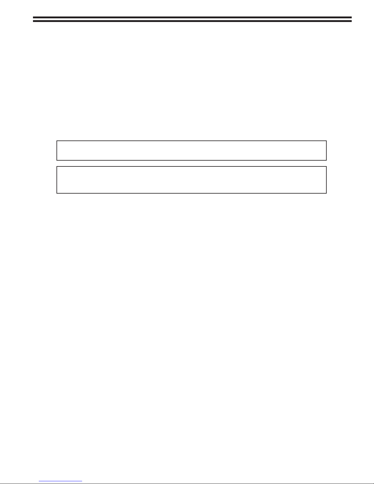
Figure 2 - Typical Installation
Figure 3 - Water Supply Piping
WATER
FEED
INLET
VENT/
OVERFLOW
TO
DRAIN
WATER SUPPLY PIPING WITH PURGE METER WATER SUPPLY PIPING WITH SOLENOID VALVE
DRAIN
TO
WATER
FEED
INLET
S
WATER SUPPLY PIPING - MANUAL FEED
OVERFLOW
VENT/
VENT/
OVERFLOW
AIR GAP
REQUIRED REQUIRED
AIR GAP
OVERFLOW
VENT/
TO
DRAIN
REQUIRED
AIR GAP
VENT/
OVERFLOW
OVERFLOW
VENT/
INLET
FEED
WATER
3/4 INCH ELECTRICALLY-ACTUATED
PRESSURE REDUCING AND
SHUT-OFF VALVE. SET AT
1 X 1/4
AND AMMONIA SERVICE AND
40 PSIG FOR CHLORINE
DIOXIDE SERVICE. (SEE NOTE 8)
15 PSIG FOR SULFUR
SHUT-OFF VALVE
PIPE LINE
(AMMONIA TYPE)
FLANGE UNION
INSULATION
EMERGENCY AND SERVICING VENT LINE
VENT LINE (SEE NOTE 7)
PRESSURE REDUCING AND SHUT-OFF VALVE
OUTSIDE WALL
INSECT
SCREENS
NOTES:
1. FOR LOCATION, MOUNTING AND ADDITIONAL PERTINENT INFORMATION, REFER TO
THE INSTALLATION SECTION.
2. PIPING AND FIXTURES TO BE 1 INCH 25 MILLIMETERS, EXCEPT AS NOTED, AND
CONSTRUCTED OF MATERIALS SUITABLE FOR CHEMICAL SERVICE IN QUESTION,
3. REFER TO INSTRUCTION BULLETIN 010.3650 FOR MATERIALS OF CONSTRUCTION
AND INTERCONNECTION PRACTICES.
4. SUPPORT ALL PIPE RUNS THEIR ENTIRE LENGTH.
5. AIR PADDING AT SOURCE REQUIRED IF TEMPERATURE OF SUPPLY IS EXPECTED
TO FALL BELOW SPECIFIED MINIMUM. PADDING TO BE 40 PSIG MINIMUM FOR
CHLORINE, 50 PSIG MINIMUM FOR AMMONIA AND 35 PSIG MINIMUM FOR
SULFUR DIOXIDE; 100 PSIG MAXIMUM, ALL INSTANCES. SEE CHLORINE INSTITUTE
6. REQUIRED TO PERMIT REMOVAL OF VAPORIZING CHAMBER FOR CLEANING AND
INSPECTION.
7. LINE SIZE BASED ON MANUFACTURERS' RECOMMENDATIONS.
8. PIPE RUN BETWEEN VAPORIZER AND THIS VALVE SHOULD BE AS SHORT AS
POSSIBLE, WITH HEAVY INSULATION (2 INCH THICKNESS TYPICAL) AS SHOWN.
ALL OTHER PIPES TO BE WITHOUT INSULATION.
9. PIPING SHOWN IS FOR RECOMMENDED INSTALLATION PURPOSES ONLY, AND IS NOT
SUPPLIED WITH VAPORIZER.
VAPORIZER
REMOVABLE PIPE SECTIONS
(SEE NOTE 6)
TO GAS
VALVE MUST BE LOCKABLE IN CLOSED POSITION.
OPTIONAL: 1 INCH OR 1/2 INCH BYPASS LINE AND VALVE.
SECTION 13, DIVISION 1, PARAGRAPH UG-125
MANDATORY BY ASME BOILER AND PRESSURE VESSEL CODE
SET AT 300 PSIG FOR ALL THREE CHEMICAL SERVICES.
1 INCH PRESSURE RELIEF VALVE.
1 INCH X 3/4 INCH REDUCERS,
IF REQUIRED
PAMPHLET #66 FOR AIR PADDING REQUIREMENTS.
10. IT IS RECOMMENDED TO INSTALL AN IN-LINE GAS FILTER BETWEEN THE VAPORIZER
AND THE PRESSURE REDUCING VALVE.
(SEE NOTE 10)
GAS
FILTER
DISPENSERS
FROM LIQUID CHEMICAL SUPPLY
AT 32°F MINIMUM FOR CHLORINE
AND AMMONIA AND 70°F
MINIMUM FOR SULFUR DIOXIDE.
(SEE NOTE 5)
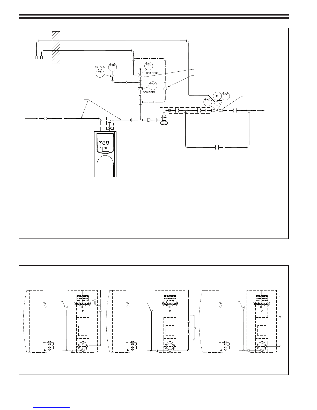
- 17 - 115.6031.0
Figure 4 - Outline & Mounting Dimensions
12 kW & 15 kW Heaters
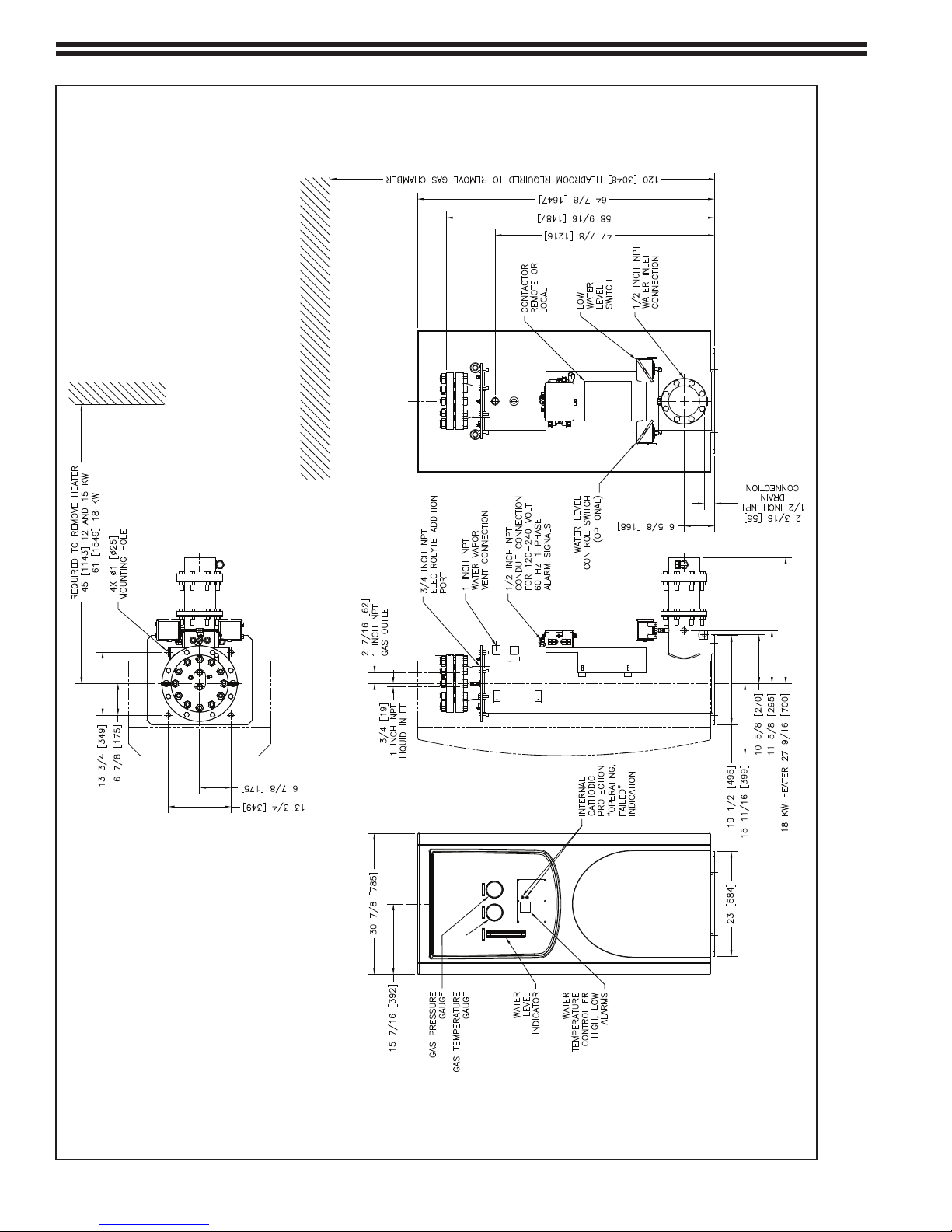
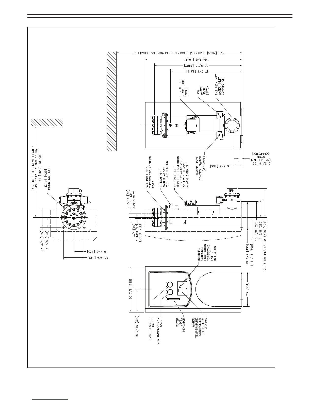
115.6031.0 - 18 -
Figure 5 - Outline & Mounting Dimensions
18 kW Heater

- 19 - 115.6031.0
Figure 6 - Interconnection & Wiring Diagrams for Vaporizers with Integral Magnetic Heater Contactor and LOVE Controller

115.6031.0 - 20 -
Figure 7 - Interconnection & Wiring Diagram for Vaporizers with Remote Magnetic Heater Contactor and LOVE Controller
Table of contents


