DE VERE 504 Series User manual
I
~
c:::::J
c
r.=:::::::::J
ENLARGING
WITH
DEVERE
504
ENLARGER
Models
:-
DVB
/ DVW/
DVF
/DVF
Extd.
'i.
'r
Head
OffICI:
Principal FKtory &
Foundry:
London
Showroom: Northern Showroom:
USA
Office: Call.ldi.n
OffICe:
DE
VERE
(Kensington
I
Ltd.,
DE
VERE
(Kensingtonl
Ltd.,
DE
VERE
DE
VERE
DE
VERE
ISalesllnc
.•
DE
VERE
(Sales
I
Canada
Inc.
VulC3nWay.
Riverside
Road,
51152
Frith
Street,
Churchgale
Chambers.
Oakland
Center,
1093
Britannia
Road
E.
New
AddmolOn
Potting
ton
Industrial
Estate,
London
WlV
STE.
UK
48
&
"SA
Church9ale.
8980
Route
lOO,
Columbia,
MISSISSAUGA.
Croydon
cho
9UG
BARNSTAPLE.
N.
Devon,
r 01-434,4239
STOCKPORT.
Maryland
21045.
USA.
Qnlsno
L4W
3XL
..
06894~2~2
EX311tn.
UK
.
Cheshire,
SKI IYG
ft
13011596·3388 t (416) 673,8711
..r946252
Fax:
0689
41075
tt
0271·7327316
'!t
061·477
552011
..r
4422011
f
Q6.968764
DE
VERE
504
VERTICAL
ENLARGER
TABLE
OF
CONTENTS
DESCRIPTION
PAGE
Table
of
Conlents
I
-11
lisl
of
Illustrations in
Sectlpn
One
SpeciricaUon
1- 1
120/240V
Code
Number
Conversion Charl
1-4
Sectlen
T.e
Delivery
and
Unpacking
1.
DVB&DVW
2 - 1
3.
DVF
&
DVF
Extended
2-2
Sectlen
Three
InstaIJationand
Assembly
1.
Assembly
or
504
DVB
2.
Assembly
of
504
DVW
3.
Assembly
or
504
DVF
&
DVF
Extended
4.
Fixing
to
the
Darkroom
wIII(DVW)
5.
InstaIJatlonor
504 DW
6.
Colour
500
Analyser
7. ElectrlcllComecUons
8.
FilUng
the
Lightsourca
Appendix
1.
ElectrlcalConnecUons
3-1
3 - I
3 - I
3-2
3-2
3-3
3-3
3-3
3
-I
- 1
Sectlen
Four
Guide
10
Controls
and
Ha
jor
Components
1.
Four
Way
Negative
Masking
2.
Negalive
Carrier
3. Dlchromalllghtsource
4. Correction Tilts
5.
Negslive
Carrier
lin
Pins
6.
Lens
and
Negative
Stage
Adjusting
Handwheels
7.
Transformer/Stabilizer
(TRANSTAB)
8.
Universal
Timer
9. lens Panels
10.
The
Column
Appendix
I.
lens
Panel
Application
Appendix
2.
Negative
Carrier
Combinations
4-1
4-1
4-2
4-2
4-2
4-3
4-3
4-3
4-4
4-4
4-1-1
4-2-1

Section
Fivo
Accessories
1.
AnclllryComponents
5-1
2.
Drop
Table
Assembly
5-1
3.
Copy
Adaptor
(Copybad:)
5 - 1
4.
Lens
P_I
Extension
Tube
5-1
5. Vricon
(Black
&
White
Head)
5-1
6. VrlconPointsource
Conversion
Kit
5-2
7.
Dircon
5-3
8.
Cathomsg
5-3
9. VricontrastHead
5-3
10. 70nvn
Roll
Film
Drawer (Mart
JI)
5-3
11.
Pin
Register Carrier
5-4
Appendix
1.
List
of
AnclllryComponents
Appendix
2. Vricon
Condenser
Combinations
5-1-1
5-2-1
Section
SI,
[:1alntenance.
Replacements
and
Adjustments
1
.a.
General
M1tntenance
6-1
b.
Replacements
(j)
Dichromat
Lamps
(tt
4) 6 - 1
(11)
DidV'omat
Lamps
(Mk
5) 6 - 1
Oil)
Display
Panel
illumination
Bulb
(Dichromat)
6-2
(Iv)
VarlconUghtsource
6-2
(v)
Cathomag
6-2
(vi)
Drive
Cable
Replacement
DWIOVW
6-2
(vii)
Drive
Cable
Replacement
DVF
IOVF
Exld
6-4
c.
Adjustments
(j)
Head
Support
Plate
Nylon
Tension
Rollers
6-5
(ii)
Drive
Cable
Tension
6-6
UII)
Drop
Table
Drive
Ch.lns
6-7
(iv)
Lens
and
Negative
Stage
TiltMechanisms
6-7
(v)
Tenslonlng
Negative
and
Lens
Stage
Handwheels
6-7
(vi)
Lens
Panel
Retaining
Bosses
6-8
Attachments
Spare Parts
List
Edition
1 -
Jan
64
2 -
Dec64
ii
504
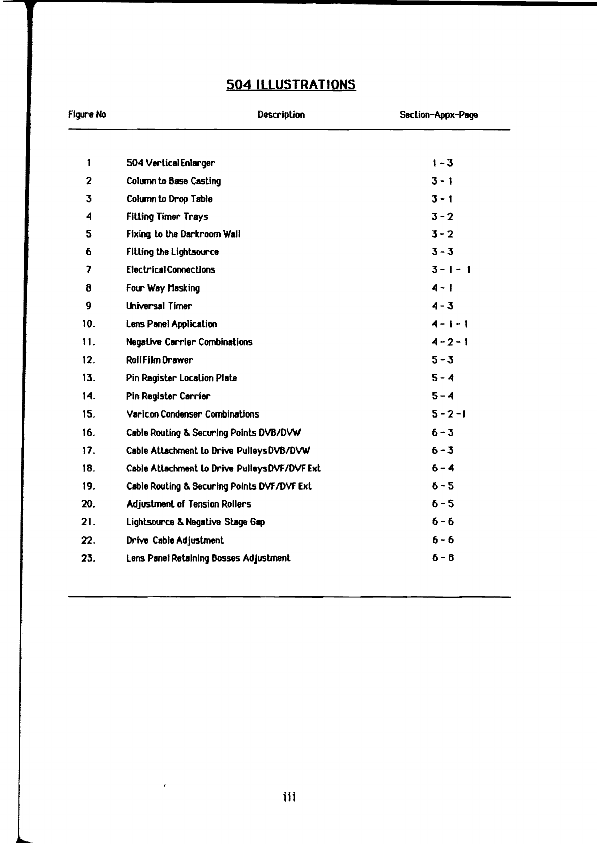
ILLUSTRATIONS
Figure
No
Description
Seclion-Appx-Page
1 504 Vertical
Enlarger
1-3
2
CoII.IM
to 8ase
Casting
3-1
3
Column
to
Drop
Table
3-1
4
Filling
Timer
Trays
3-2
5
Fixing
lo
the
Darkroom
Wall
3-2
6
FILUng
the Lighbource
3-3
7 Electrical
Connections
3-1-
8
Focr
Way
Masking
4-1
9
Universal
Timer
4-3
10.
Lens
Panel
Application
4 - 1- 1
11.
Negative
Carrier
Combinations
4-2-1
12.
Roll
Film
Drawer
5-3
13.
Pin
Register
Location
Plate
5-4
14.
Pin
Register Carrier
5-4
15.
Varicon
Condenser
Combinations
5
-2-1
16.
Cable
Routing
&
Securing
Points
DWIOVW
6-3
17.
Cable
Altadvnenllo
Drive
PullaysDVB/DVW
6-3
18.
Cable
Atlachmentlo
Drive
PuUeysDVF
IOVF
Exl
6-4
19.
Cable
Routing
&
Securing
Points
DVF
IOVF
Exl
6-5
20.
Adjustmenl
of
Tension
Rollers
6-5
21.
Lighlsource
&
NegaUva
Stage
Gap
6-6
22.
Drive
Cable
Adjustment
6-6
23.
Lens
Panel
Retaining
Dosses
AdJustmenl
0-6
Hi

SECTION
ONE
SPECIFICATION
The
De
Vere
5Q.4
Enlarger
Is
designed
ror
both
colour
and
black
and
white
printing
with
readily
Interchangeable
IIghlsol.J"Ces.
It wlllaccept
negative
rormals
up
to
and
Including
~in
x
51n
(10cm
x
12.5cm)
and
embodies
both
rigidity or
design
and
excellentoperational reliabilily.
CurrenUy
rour
versions
or
the
50~
are
8Vllllable.
these are:
I.
Model
DV6
b.
Model
DWI
c.
Model
DVF
d.
Model
DVF
Extnd
Colour
500 Analyser
ColotrHead
A
Bench
mounted
machine
with
the
rront
of
table
controls
and
a
2~in
x
2~in
(61cm
x 61cm)
baseboard
mted.
A win
moooted
machine
with
6ase lewl controls.
Adrop table is
8Vllilable
as
an
extrl
which
will
then
enable
prlnls
up
to
Ind
Including
321n
x
~In
(81
cm
x
107cm)
to
be
made.
A rree slMdlng
machine
with adjustable table and
rront
or
bench
controlsIlIowlngprlnls
up
to
321n
x
~21n
(81cm
x
107cm)
to
be
made.
Baslclllythe
same
as
the
DVF
Model
but
has
a
161n
(~)
longer
column
and
I
621n
x
~In
(l57.Scm x
107cm)
baseboard
ntted.
The
De
Vere
Colour
500 Analyser is I ractory
fitted extra
8Vlllllble
with
the
Colotr Enlarger.
This
InIlyser reatures
completely
automatic
exposure,
digital
readout.
magnification
scale
and
progrlmmable
plug-In
modules.
Dichromlt A dirfused.
dial
in
dichroic
colour
head
with
stapless
rade
rree filtration calibrated
between 0 - 200.
Two
varsions are
available:
(j)
Mark
~:
using
one
2~
voll const..nl colour
temperature llIlgslen
hllogen
lamp
giving
250
watls
or
lightoutput.
(11)
Mart 5:
USing
two
or
the
2~
volt conlslant
colotr temperlture tungsten
hllogen
lamps
used
in
the
Mark~.
thererore
giving
twice
the
light
output. 500
wltls
complete
with
shutter.
Various
lighlboxes
to
concentrate the output are
8Vlllllble
If
requIred
ror
both
IIghlsotrces.
1-1
This manual suits for next models
3
Table of contents
Popular Laboratory Equipment manuals by other brands


Belden
Belden HIRSCHMANN RPI-P1-4PoE installation manual

Koehler
Koehler K1223 Series Operation and instruction manual

Globe Scientific
Globe Scientific GCM-12 quick start guide

Getinge
Getinge 86 SERIES Technical manual

CORNING
CORNING Everon 6000 user manual

Biocomp
Biocomp GRADIENT MASTER 108 operating manual


