DEBIX BPC-iMX8MP-05 User manual

Polyhex Technology Company Limited
www.debix.io
1/29
BPC-iMX8MP-05 Industrial
Computer User Guide
Version: V1.0(2023-04)
Complied by: Polyhex Technology Company Limited(http://www.polyhex.net/)
BPC-iMX8MP-05 Industrial Computer is a ruggedized and protected computer. It is composed
of a DEBIX SOM A (core board), a DEBIX SOM A I/O board (carrier board), 2 custom Interface
Board and a steel and aluminum enclosure. It combines various types of harsh environment
resistance features, including ruggedness, dustproof, anti-vibration, shock resistance, wide
temperature, portability and other indicators.
Figure 1

Polyhex Technology Company Limited
www.debix.io
2/29
INDEX
1. Applicable objects ...................................................................................................................4
2. Security ...................................................................................................................................4
2.1. Safety Precaution ........................................................................................................ 4
2.2. Safety Instruction .........................................................................................................4
2.3. Technical Support ........................................................................................................6
3. Overview .................................................................................................................................7
3.1. Overview of Construction ............................................................................................ 7
3.2. Interface .......................................................................................................................9
3.2.1. Power Interface ................................................................................................ 9
3.2.2. Ethernet Interface ...........................................................................................10
3.2.3. USB Interface ................................................................................................. 11
3.2.4. HDMI Interface ............................................................................................... 12
3.2.5. Audio Interface ............................................................................................... 12
3.2.6. I2C Interface ................................................................................................... 13
3.2.7. DI & DO Interface ........................................................................................... 14
3.2.8. CAN Interface .................................................................................................16
3.2.9. RS485 Interface ............................................................................................. 16
3.2.10. RS232 & UART Interface ............................................................................. 17
3.2.11. L&R Speaker Interface ................................................................................. 18
3.2.12. LED & Key Interface .....................................................................................19
3.3. Packing List ............................................................................................................... 20
4. Installation Guide ..................................................................................................................21
4.1. Software Installation .................................................................................................. 21
4.2. Hardware Installation .................................................................................................22
5. Operation Instructions .......................................................................................................... 24
5.1. Usage of Ethernet ..................................................................................................... 24
5.2. Usage of WiFi ............................................................................................................25

Polyhex Technology Company Limited
www.debix.io
3/29
5.3. Usage of Bluetooth ....................................................................................................26
5.4. Usage of USB ............................................................................................................27
5.5. Usage of LED and Key ..............................................................................................29
Polyhex Technology Company Limited
www.debix.io
4/29
1. Applicable objects
This product applies to all personnel who come into contact with BPC-iMX8MP-05 device,
including but not limited to developers, maintenance technician, installation, repair, etc.
All users must read and fully understand contents of the manual.
2. Security
2.1. Safety Precaution
The following messages inform how to make each cable connection. In most cases, you will
simply need to connect a standard cable.
2.2. Safety Instruction
To avoid malfunction or damage to this product please observe the following:
1.Disconnect the device from the DC power supply before cleaning. Use a damp cloth. Do
not use liquid detergents or spray-on detergents.

Polyhex Technology Company Limited
www.debix.io
5/29
2.Keep the device away from moisture.
3.During installation, set the device down on a reliable surface. Drops and bumps will lead to
damage.
4.Before connecting the power supply, ensure that the voltage is in the required range, and
the way of wiring is correct.
5.Carefully put the power cable in place to avoid stepping on it.
6.If the device is not used for a long time, power it off to avoid damage caused by sudden
overvoltage.
7.Do not pour liquid into the venting holes of the enclosure, as this could cause fire or
electric shock.
8.For safety reasons, the device can only be disassembled by professional personnel.
9.If one of the following situations occur, get the equipment checked by service personnel:
The terminal block is damaged.
Liquid has penetrated into the equipment.
The equipment has been exposed to moisture.
The equipment does not work well, or you cannot get it to work according to the
user's manual.
The equipment has been dropped and damaged.
The equipment has obvious signs of breakage.
10.Do not place the device in a place where the ambient temperature is below -20°C (-4°F)
or above 70°C (158°F). This will damage the machine. It needs to be kept in an environment
at controlled temperature.
DISCLAIMER: Polyhex disclaims all responsibility for the accuracy of any statement of this
instructional document.


Polyhex Technology Company Limited
www.debix.io
7/29
3. Overview
3.1. Overview of Construction
Figure 2 Interface above enclosure
Figure 3 Interface under enclosure
BPC-iMX8MP-05 uses DEBIX SOM A, DEBIX SOM A I/O Board and custom Interface Board

Polyhex Technology Company Limited
www.debix.io
8/29
as the main board, which supports dual Gigabit Ethernet, WiFi, Bluetooth, etc. It is dustproof,
shock resistant, vibration resistant, etc. The specific specifications are as follows:
System
Main Board
DEBIX SOM A + I/O Board + 2 x custom Interface Board
Type
BPC-iMX8MP-05
Storage
Onboard 2GB LPDDR4 + 16GB eMMC
OS
Ubuntu 20.04 (Desktop version)
Communication
Ethernet
2 x Independent MAC RJ45 Gigabit Ethernet ports
Wi-Fi & Bluetooth
2.4GHz & 5GHz dual-band Wi-Fi, Bluetooth 5.0, external Wi-Fi
SMA antenna interface
Video & Audio
HDMI
1 x HDMI output, connector is Type A HDMI female
Audio
(1) 1 x headphone output and microphone input combo interface,
the connector is a 3.5mm socket
(2) 1 x 4Pin/3.5mm L&R Speaker
I/O Interface
DC Block
1 x DC socket, supports 5.5mm x 2.1mm plug
USB
(1) 4 x USB 3.0 Host, the connector is double layer Type-A
interface
(2) 2 x USB 2.0 Host, the connector is Type-A interface
Serial Ports
(1) 1 x I2C, 3.3V power supply
(2) 2 x physically isolated CAN
(3) 2 x physically isolated RS485
(4) 1 x physically isolated RS232, 1 x without physical isolation
UART TTL 3.3V
The connectors are 6pin/3.5mm Phoenix terminals

Polyhex Technology Company Limited
www.debix.io
9/29
3.2. Interface
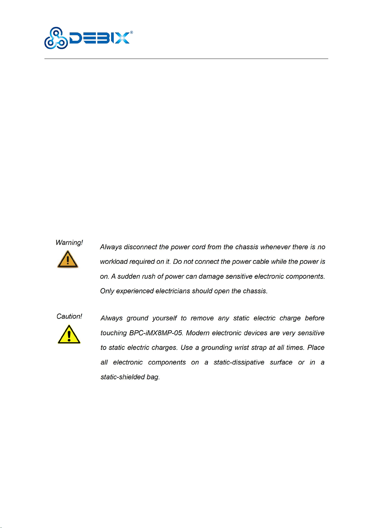
3.2.1. Power Interface
There is 1 power connector (DC socket), with default DC 12V power input. As shown in the
figure below.
GPIO
(1) 2 x physically isolated DI, supporting wet and dry nodes
(2) 1 x physically isolated DO, support wet nodes, compatible with
external relay dry nodes
LED & Key
(1) 1 x SYS
(2) 1 x PWR
(3) 1 x ON/OFF key
Power Supply
Power Input
Default DC 12V power input, support DC 12V~36V wide voltage
input
Mechanical & Environmental
Enclosure Material
Steel and aluminum alloy
Dimension
124mm(D) x 169.42mm(W) x 38.9mm(H)
Gross Weight
830g
Heat Dissipation
No fan, heat dissipation through the enclosure
CPU Temperature
-20 °C to 70 °C
Polyhex Technology Company Limited
www.debix.io
10 /29
Figure 4 DC IN Interface
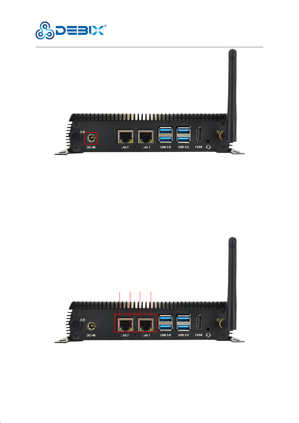
3.2.2. Ethernet Interface
Two independent MAC RJ45 Gigabit Ethernet ports on board (Network port 1: LAN1, Network
port 2: LAN2), connect device to the network through the network cable of RJ45 connector,
and there is also a set of status indicators below the interface, one is Link, connection
indicator, and the other is Active, signal transmission indicator.
Figure 5 Ethernet Interface
Link
Active
Link
Active
Polyhex Technology Company Limited
www.debix.io
11 /29
LED
Color
Description
Link
Green
Light, the network cable is plugged in, network connection status is good
Active
Yellow
Blinking, network data is being transmitted
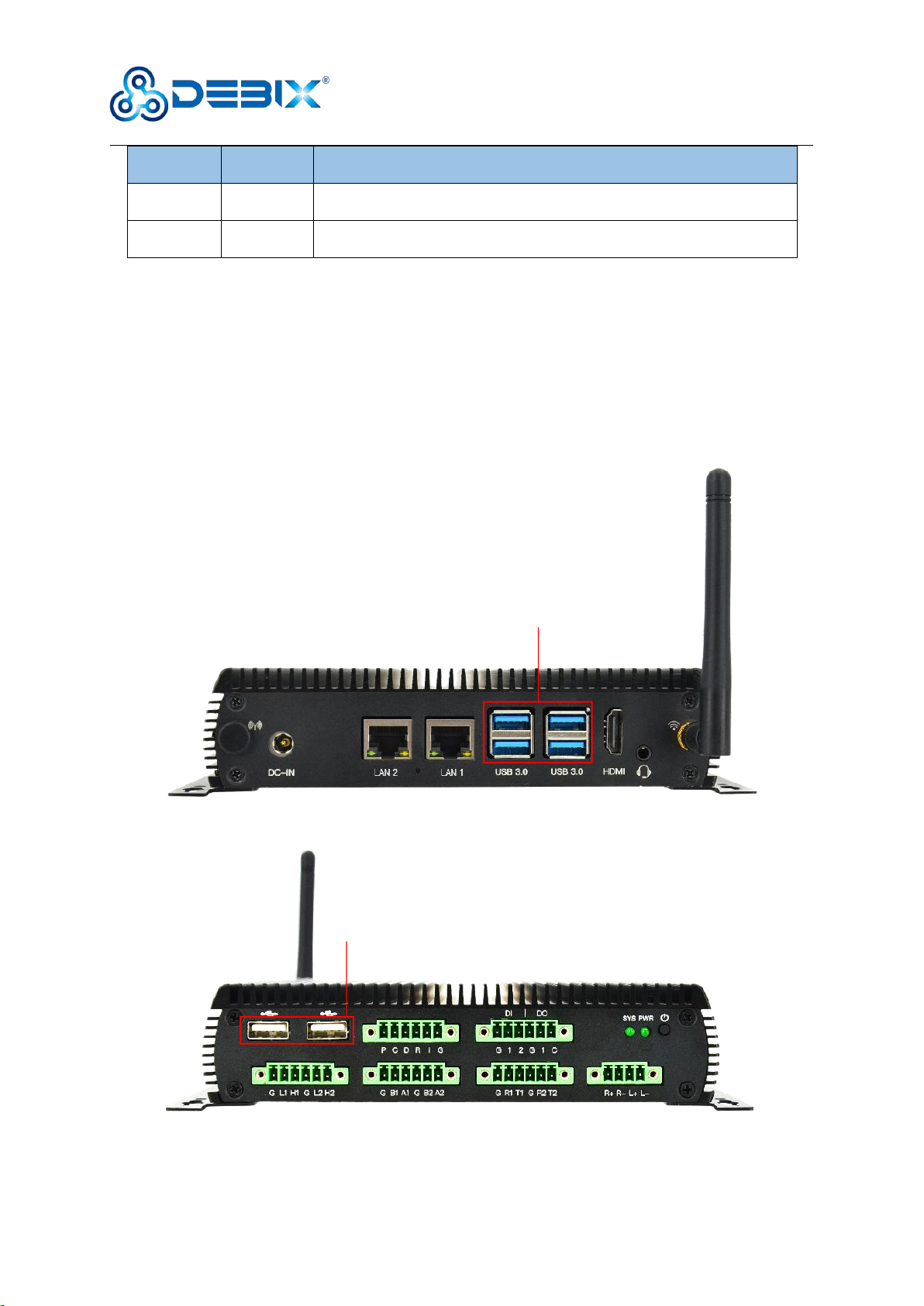
3.2.3. USB Interface
BPC-iMX8MP-05 Industrial Computer has 2 USB controllers and PHY, supports USB 3.0 and
2.0. There are four USB 3.0 interfaces with dual-layer Type-A connectors next to Ethernet
interface and two USB 2.0 interfaces with Type-A connectors on the bottom of the enclosure.
As shown in the figure below.
Figure 6 USB 3.0 Interface
Figure 7 USB 2.0 Interface
USB 3.0
USB 2.0

Polyhex Technology Company Limited
www.debix.io
12 /29
3.2.4. HDMI Interface
There is an HDMI interface, and the connector is an A-type HDMI female socket, which is
used to connect a monitor, TV or projector. As shown in the below.
HDMI resolution up to 3840x2160p30. HDCP is not supported, audio supports 32 channel
audio, output supports 1 S/PDIF audio and eARC input support.
Figure 8 HDMI Interface
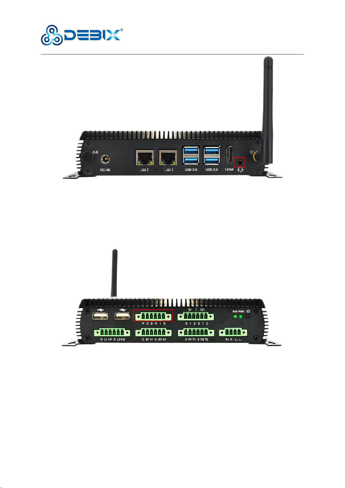
3.2.5. Audio Interface
There is a combined headphone and microphone input interface. The connector is a 3.5mm
socket, has audio input/output functions, and supports rated voltage 1.5V MIC audio input. As
shown in the below.
HDMI
Polyhex Technology Company Limited
www.debix.io
13 /29
Figure 9 Audio Interface
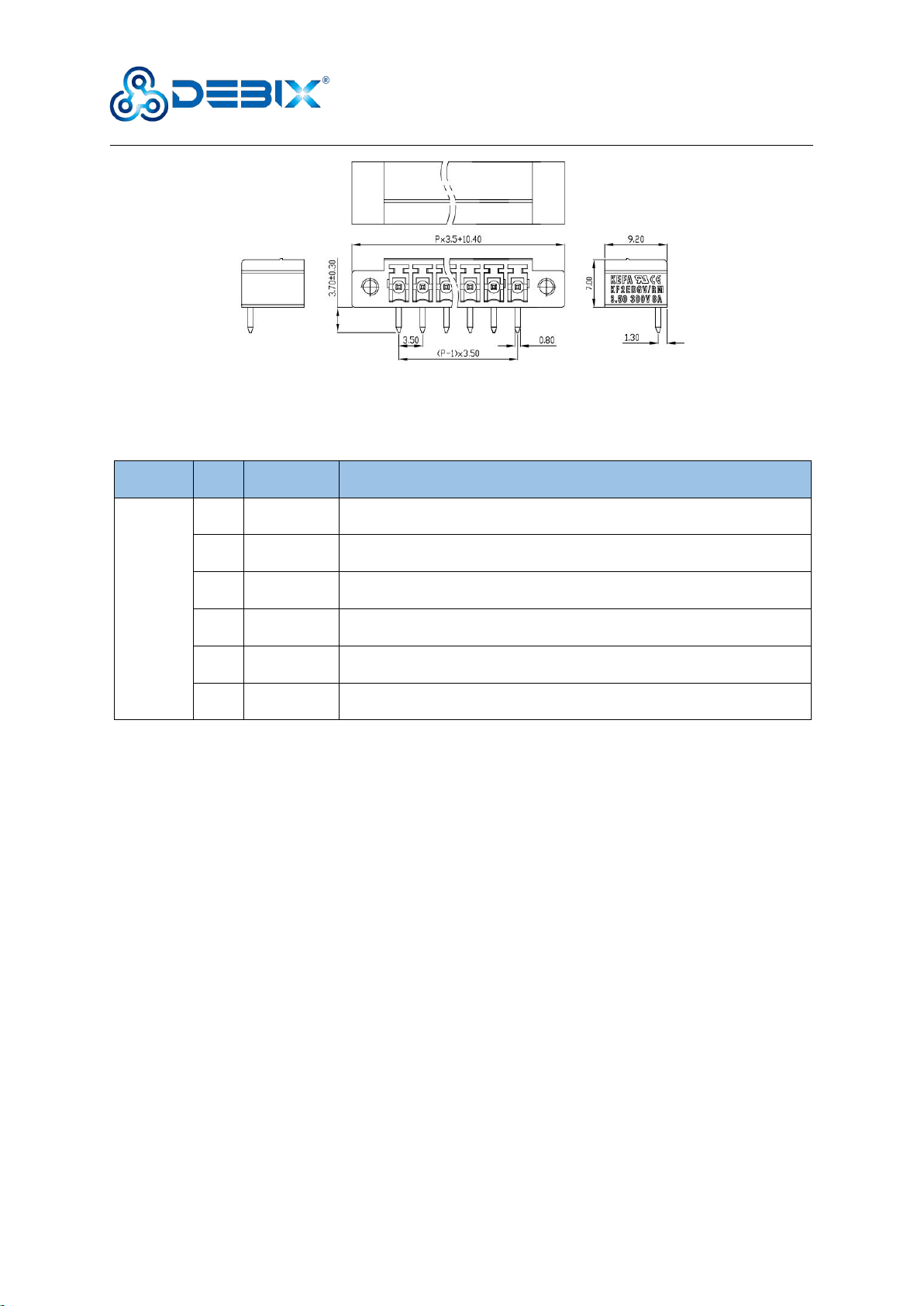
3.2.6. I2C Interface
BPC-iMX8MP-05 has a set of 6pin I2C bus interface with 3.5mm pitch connector and 3.3V
power supply by default. As shown in the figure below:
Figure 10 I2C Interface
Polyhex Technology Company Limited
www.debix.io
14 /29
Figure 11 6pin Phoenix terminal
The I2C interface is defined as follows:
Function
Pin
Definition
Description
I2C
P
I2C-3.3V
I2C bus power, Output 300mA power supply
C
I2C-SCL
Serial clock output I2C bus line,CMOS 3.3V voltage level
D
I2C-SDA
Serial data output I2C bus line,CMOS 3.3V voltage level
R
I2C-RESET
Reset signal output I2C bus line, default pull-up voltage level is 3.3V
I
I2C-nINT
Interrupt signal input I2C bus line, default pull-up voltage level is 3.3V
G
I2C-GND
I2C bus Ground
3.2.7. DI & DO Interface
There are 2 x DI & 1 x DO interfaces with isolated type (from left to right, DI interface, DO
interface), physically isolated DI, supports dry node input and wet node input; physically
isolated DO, supports wet node, and is compatible with external relay dry nodes. As shown in
the figure below:

Polyhex Technology Company Limited
www.debix.io
15 /29
Figure 12 DI & DO Interface
The interface is defined as follows:
Function
Pin
Definition
Description
Device node
DI
G
DI-GND
Digital isolation input Ground
1
DI-1#
Digital isolation input channel 1#
DIN1
2
DI-2#
Digital isolation input channel 2#
DIN2
DO
G
DO-GND
Digital isolation output Ground
1
DO-1#
Digital isolation output channel 1#
C
DO-PCOM
Digital isolation power input
DI electrical parameters:
Wet contact:
When the signal input voltage is 0~3V DC, the corresponding device signal is low
level;
When the signal input voltage is 5~30V DC, the corresponding device signal is high
level.
Dry contact:
Open state: high level
Short state with GND: low level
DO electrical parameters:
Node DO-PCOM supports a voltage range of 5~30V DC;
Polyhex Technology Company Limited
www.debix.io
16 /29
When the device signal is low, the corresponding DO signal output voltage follows the
node DO-PCOM, the higher the node DO-PCOM voltage, the higher the DO signal output
voltage (compared with the node DO-PCOM, there is a 1~3V voltage drop);
When the device signal is high level, the corresponding DO signal output voltage is 0.
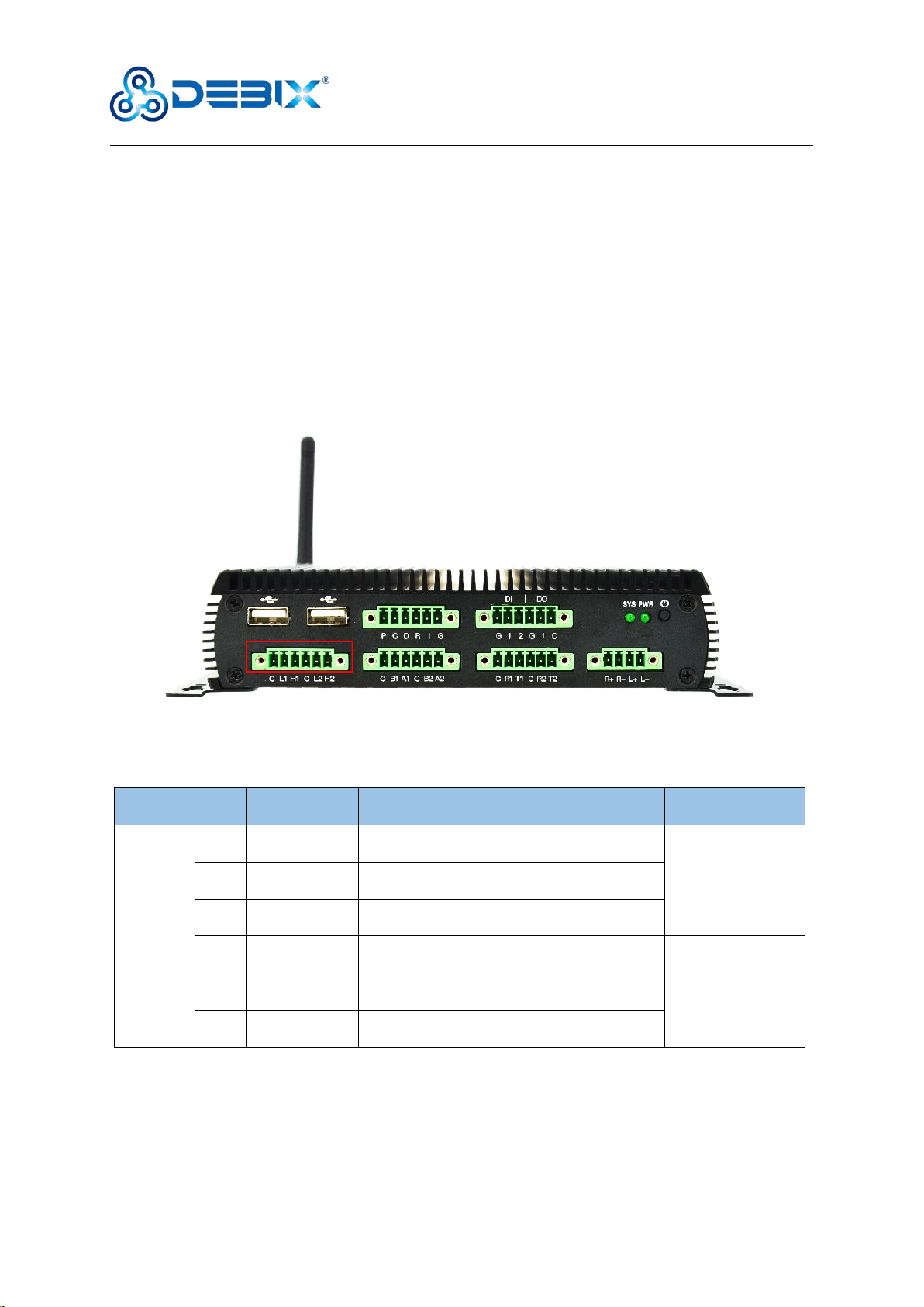
3.2.8. CAN Interface
There are 2 x CAN bus interfaces with physical isolation below USB 2.0 interface. As shown in
the following figure:
Figure 13 CAN Interface
The CAN interface is defined as follows:
Function
Pin
Definition
Description
Device node
CAN
G
CAN-1#-GND
CAN bus 1# Ground for reserved
can0
L1
CAN-1#-L
LOW-level CAN bus 1# line
H1
CAN-1#-H
HIGH-level CAN bus 1# line
G
CAN-2#-GND
CAN bus 2# Ground for reserved
can1
L2
CAN-2#-L
LOW-level CAN bus 2# line
H2
CAN-2#-H
HIGH-level CAN bus 2# line
3.2.9. RS485 Interface
There are 2 x RS485 interfaces with physical isolation. As shown in the following figure:

Polyhex Technology Company Limited
www.debix.io
17 /29
Figure 14 RS485 Interface
The RS485 interface is defined as follows:
Function
Pin
Definition
Description
Device node
RS485
G
RS485-1#-GND
RS485 bus 1# Ground for reserved
/dev/ttyWCH0
B1
RS485-1#-B
Inverting RS485 bus 1# line
A1
RS485-1#-A
Noninverting RS485 bus 1# line
G
RS485-2#-GND
RS485 bus 2# Ground for reserved
/dev/ttyWCH1
B2
RS485-2#-B
Inverting RS485 bus 2# line
A2
RS485-2#-A
Noninverting RS485 bus 2# line
3.2.10. RS232 & UART Interface
There are a set of RS232 with physical isolation and UART without physical isolation
interfaces. As shown in the figure below:

Polyhex Technology Company Limited
www.debix.io
18 /29
Figure 15 RS232 & UART Interface
The interface is defined as follows:
Function
Pin
Definition
Description
Device node
RS232
G
RS232-1#-GND
RS232 bus 1# Ground
/dev/ttyWCH2
R1
RS232-1#-RXD
Receiver input RS232 bus 1# line
T1
RS232-1#-TXD
Transmitter output RS232 bus 1# line
UART
G
UART-2#-GND
UART bus 2# Ground
/dev/ttyWCH3
R2
UART-2#-RXD
Receiver input UART bus 1# line, CMOS 3.3V
voltage level
T2
UART-2#-TXD
Transmitter output UART bus 1# line, CMOS
3.3V voltage level
3.2.11. L&R Speaker Interface
One set of 4-pin L&R Speaker interface with 3.5mm pitch connector. As shown in the following
figure.
Support dual audio channel
Support 4Ω 3w or 8Ω 1.7W speaker

Polyhex Technology Company Limited
www.debix.io
19 /29
Figure 16 L&R Speaker Interface
The SPK interface is defined as follows:
Function
Pin
Definition
Description
SPK
R+
Speaker Rout+
Right channel speak positive output
R-
Speaker Rout-
Right channel speak negative output
L+
Speaker Lout+
Left channel speak positive output
L-
Speaker Lout-
Left channel speak negative output
3.2.12. LED & Key Interface
There are two LED indicators and a power ON/OFF key, as shown in the figure below.
Figure 17 LED & Key
SYS
PWR
ON/OFF Key
Polyhex Technology Company Limited
www.debix.io
20 /29
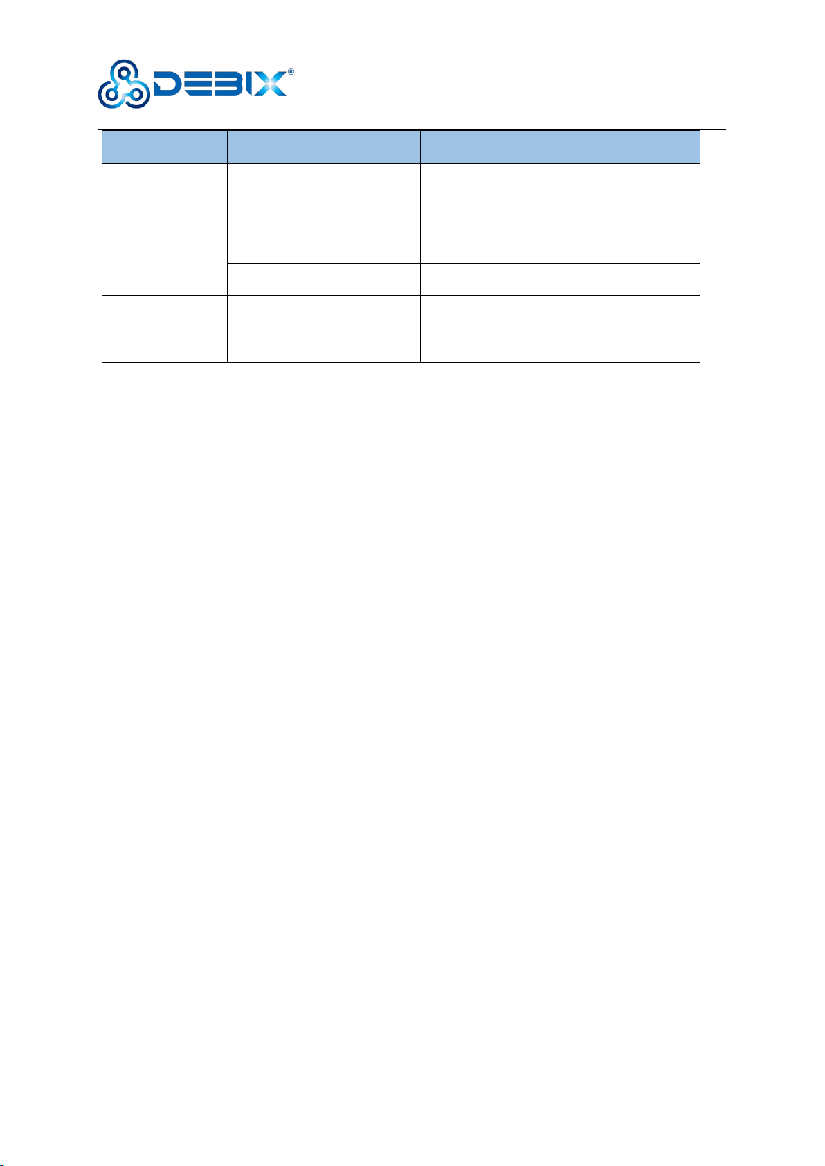
LED & Key
Status
Description
SYS
Lighting
Device works normally
off
Device works abnormally
PWR
Lighting
Power is on
off
Power is off
ON/OFF key
Short press
Hibernation/wake up
Long press
Power off/on
3.3. Packing List
1 x WiFi external antenna
4 x M3-5 Black screw
2 x Wall bracket
1 x BPC-iMX8MP-05 box
Table of contents
Other DEBIX Industrial PC manuals


Popular Industrial PC manuals by other brands


Siemens
Siemens SIMATIC IL43 operating instructions

IBASE Technology
IBASE Technology SI-58 Series user manual

IEI Technology
IEI Technology ECN-360A-ULT3-C/4G-R10 user manual

Advantech
Advantech EPC-R3430 user manual

AXIOMTEK
AXIOMTEK tBOX321-870-FL Series Quick installation guide

Louet
Louet Megado Computer Dobby 2.0 manual