SeaLevel Relio R5200 Series User manual

Sealevel Systems, Inc.
Sealevel.com
Phone 864.843.4343
Relio Fanless Core™2 Duo R5200 Series

©Sealevel Systems, Inc.
SL9222 07/2011
Relio R5200 Manual
1
Contents
Before You Get Started......................................................................................................................................3
What‘s Included..............................................................................................................................................3
Advisory Conventions....................................................................................................................................3
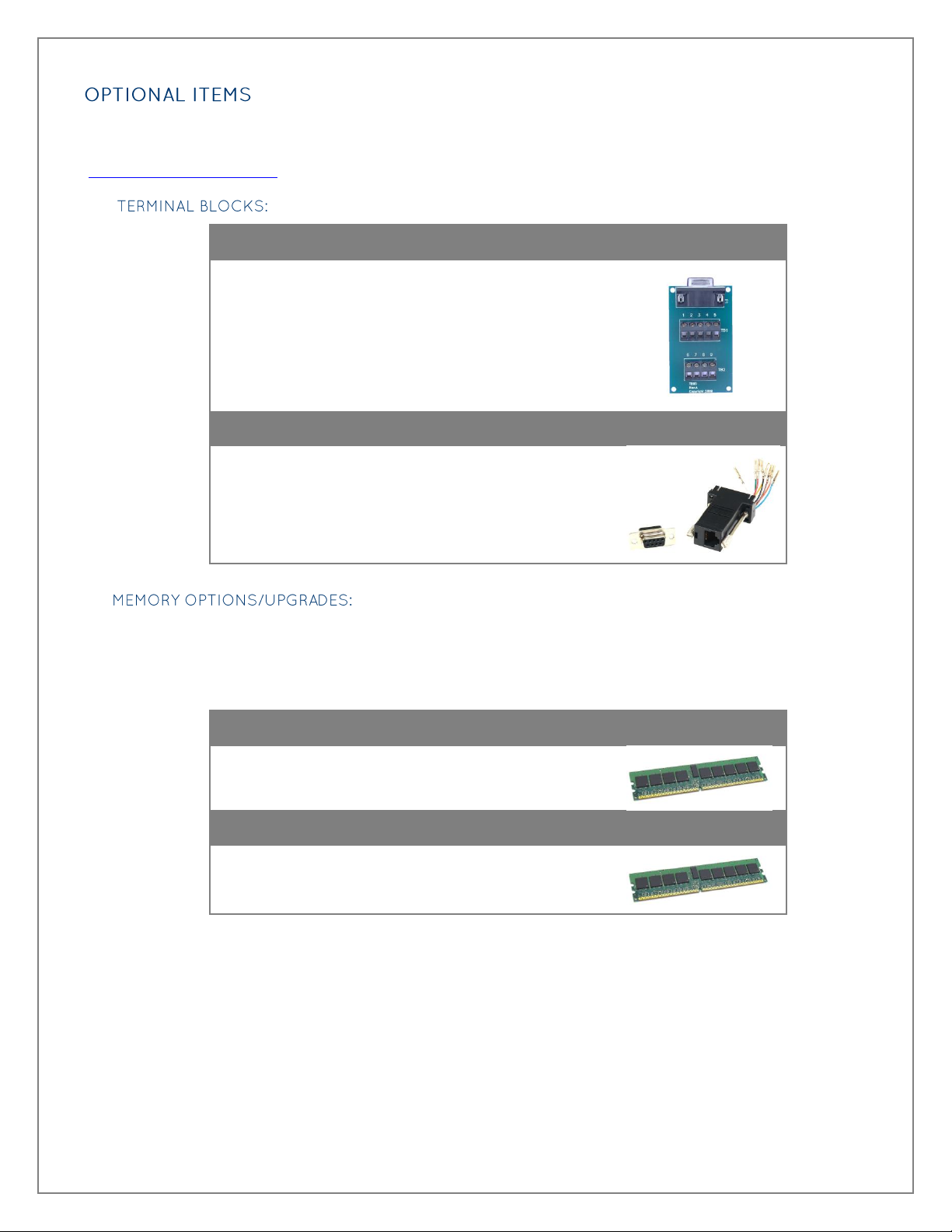
Optional Items................................................................................................................................................ 4
Introduction .......................................................................................................................................................6
Features .......................................................................................................................................................... 6
Hardware Installation ........................................................................................................................................8
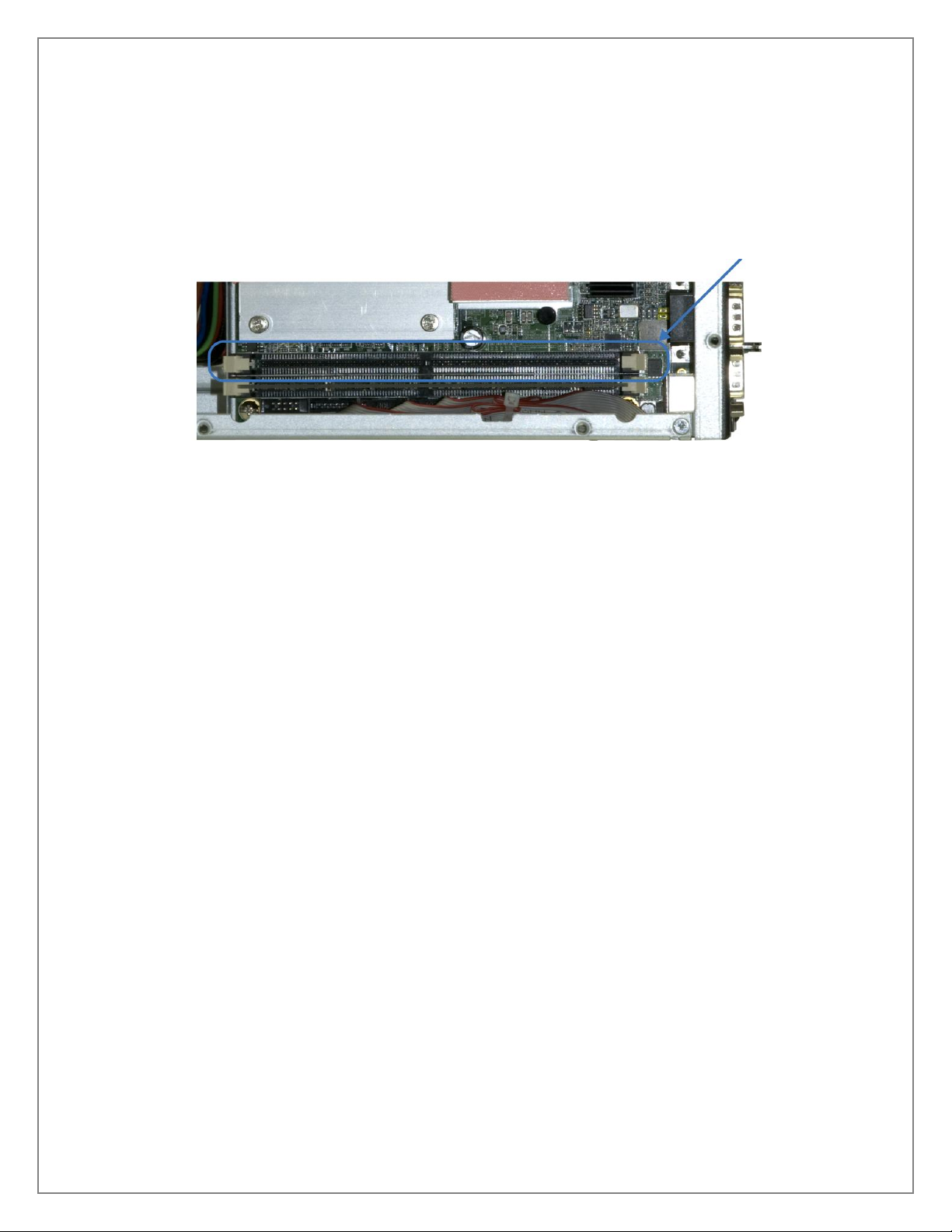
Installing System Memory .............................................................................................................................8
Installing a Solid-State Disk Drive...............................................................................................................10
Installing Expansion Cards..........................................................................................................................12
Technical Description .....................................................................................................................................20
Motherboard Layout –Component Side.....................................................................................................20
Motherboard Layout –Solder Side..............................................................................................................21
Component & Connector Locations............................................................................................................22
Jumper Descriptions & Locations ...............................................................................................................24
Connector Pinouts .......................................................................................................................................33
Input Power ..................................................................................................................................................38
Specifications...................................................................................................................................................39
Motherboard.................................................................................................................................................39
Environmental ..............................................................................................................................................39
Dimensions...................................................................................................................................................39
Appendix A –Handling Instructions ..............................................................................................................40
ESD Warnings ...............................................................................................................................................40
Appendix B –Phoenix Award BIOS.................................................................................................................41
Introduction..................................................................................................................................................41
Entering Setup..............................................................................................................................................41
Control Keys .................................................................................................................................................42
Getting Help .................................................................................................................................................43
The Main Menu.............................................................................................................................................43
Standard CMOS Setup Menu .......................................................................................................................44
Advanced BIOS Features ..............................................................................................................................46
Advanced Chipset Features.........................................................................................................................51
Integrated Peripherals .................................................................................................................................54
Power Management Setup ...........................................................................................................................58
PnP/PCI Configuration Setup ......................................................................................................................62
PC Health Status...........................................................................................................................................63
Frequency/Voltage Control .........................................................................................................................64

©Sealevel Systems, Inc.
SL9222 07/2011
Relio R5200 Manual
2
Load Optimized Defaults.............................................................................................................................64
Set Supervisor/User Password ....................................................................................................................66
Save & Exit Setup .........................................................................................................................................67
Exit Without Saving......................................................................................................................................67
Appendix C –Booting from a USB Drive........................................................................................................68
USB drive boot capability.............................................................................................................................68
Appendix D –Watch Dog Timer .....................................................................................................................74
Appendix E –How to Get Assistance .............................................................................................................75
Technical Support ........................................................................................................................................75
Appendix F –Serial Interfaces ........................................................................................................................76
RS-232...........................................................................................................................................................76
RS-422...........................................................................................................................................................76
RS-485...........................................................................................................................................................76
Warranty...........................................................................................................................................................77
Trademarks ..................................................................................................................................................77

©Sealevel Systems, Inc.
SL9222 07/2011
Relio R5200 Manual
3
Before You Get Started
The Relio R5200 is shipped with the following items. If any of these items is missing or damaged
please contact Sealevel for replacement.
Relio R5200 Series Fanless Core 2 Duo Computer
oR5220 includes 2GB RAM
oR5240 includes 4GB RAM
100-240V AC to 24VDC @ 120W Desktop Power Supply
US Power Cord for Desktop Power Supply
Relio R5200 Support CD
Warning - The highest level of importance used to stress a condition where damage could
result to the product or the user could suffer serious injury.
Important–The middle level of importance used to highlight information that might not seem
obvious or a situation that could cause the product to fail.
Note –The lowest level of importance used to provide background information, additional tips,
or other non-critical facts that will not affect the use of the product.

©Sealevel Systems, Inc.
SL9222 07/2011
Relio R5200 Manual
4
Depending upon your application, you are likely to find one or more of the following items useful for
interfacing the Relio R5200 to real-world signals. All items can be purchased from our website
(http://www.sealevel.com) or by calling +1 864 843-4343.
DB9 Female to 9-Screw Terminals (Part# TB05)
The TB05 terminal block breaks out a DB9 connector to
9 screw terminals to simplify field wiring of serial
connections. It is ideal for RS-422 and RS-485 networks,
yet it will work with any DB9 serial connection, including
RS-232. The TB05 includes holes for board or panel
mounting. The TB05 is designed to connect directly to
Sealevel DB9 serial cards or any cable with a DB9M
connector.
DB9 Female to RJ45 Modular Adapter (Part# RJ9S8)
DB9 Female to RJ45 Modular Adapter. Excellent choice
for using available infrastructure wiring. Item ships
unassembled and can be easily configured without tools.
Relio R5200 systems have two 240-pin DIMM slots. The first slot includes 2GB RAM and ordering
options allow for a maximum of 4GB. It is recommended to order the R5200 system with memory
already integrated. The following memory is recommended for field replacement or upgrades.
1GB DDR2 240-Pin DIMM (Part# RAM1GB-667X240)
1GB DDR2 240-pin DIMM (667MHz Non-ECC CL5)
module.
2GB DDR2 240-Pin DIMM (Part# RAM2GB-667X240)
2GB DDR2 240-pin DIMM (667MHz Non-ECC CL5)
module (one included in Relio R5220 and two included
in Relio R5240).

©Sealevel Systems, Inc.
SL9222 07/2011
Relio R5200 Manual
5
Install your operating system and application on 2.5‖ SSD drives for true solid-state operation
resulting in the highest reliability. Integration options are available. Contact your sales
representative for details.
16GB SATA Solid-State Disk (Part# SSD-16GSS)
16GB 2.5‖ SATA SSD with MLC memory.
32GB SATA Solid-State Disk (Part# SSD-32GMS)
32GB 2.5‖ SATA SSD with MLC memory.
64GB SATA Solid-State Disk (Part# SSD-32GMS)
64GB 2.5‖ SATA SSD with MLC memory.
128GB SATA Solid-State Disk (Part# SSD-128GMS)
128GB 2.5‖ SATA SSD with MLC memory.

©Sealevel Systems, Inc.
SL9222 07/2011
Relio R5200 Manual
6
Introduction
The Relio R5200 fanless, dual-core industrial computer is designed for CPU-intensive applications in
industrial environments. Available with a fanless 2.2GHz Intel® Core™2 Duo processor and up to 4GB
RAM, the R5200 offers first-class performance and reliability. The system offers a wealth of standard
I/O features including dual Gigabit Ethernet, six USB 2.0 ports, four serial ports, and VGA video.
Expansion options include one full-height PCI slot and one PCI Express x16 slot.
An optional 2.5" solid-state SATA hard drive can be integrated and preloaded with Microsoft Windows
or Windows Embedded operating systems. Linux is also supported. With your operating system and
application running from solid-state hard drive, the R5200 provides the ultimate in reliability —no
moving parts.
The R5200 includes an external power supply and US power cord that accepts 100-240V AC input and
outputs 24VDC @ 120W. The metal enclosure allows for versatile mounting to walls, under counters,
and on tabletops.
Relio R5200 systems are designed for CPU-intensive applications in industrial environments and
include the following features:
Compact, rugged enclosure with silver-colored finish
Solid-state operation with no fans or other moving parts
Includes 2.2GHz Intel® Core™2 Duo processor and 2GB RAM
Mini-ITX motherboard with Intel® 965GME, VGA, and dual Gigabit LAN
Up to 4GB RAM (DDR2 533/667MHz 240-Pin DIMM, Non-ECC, CL5) via two DIMM slots
Hardware (965GME GMA X3100) integrated graphics supports QXGA resolution up to
2048x1536 @ 75Hz and 32-bit color
2.5" internal shock-mounted hard drive bay is perfect for optional solid-state disk applications
Battery backed RTC/CMOS
Watchdog Timer with 255 levels (1-255 Seconds)
Supports CPU thermal/voltage monitoring and management
Supports Wake on Ring and Wake on Alarm functions
System power management (OS dependent)

©Sealevel Systems, Inc.
SL9222 07/2011
Relio R5200 Manual
7
Two expansion slots support one PCI Express X16 and one PCI card
Two 10/100/1000BaseT RJ45 (Intel 82566DM, 82573V) Gigabit Ethernet ports with status LEDs
Four DB9M serial ports (COM1 = RS-232/422/485, COM2,3,4 = RS-232)
Six USB 2.0 ports
Two IEEE-1394 ―FireWire‖ ports
One analog VGA DB15 connector
Separate PS/2 mouse and keyboard ports
Audio line out and microphone in
LED status indicators for power and disk activity
On/Off power switch

©Sealevel Systems, Inc.
SL9222 07/2011
Relio R5200 Manual
8
Hardware Installation
Follow proper ESD procedures by grounding yourself and the computer chassis before opening the
enclosure. This will help avoid system damage resulting from static electricity discharge.
The R5200 supports a maximum of 4GB RAM via two 240-Pin DIMM slots. The memory slots accept
either 533MHz (CL4) or 667MHz (CL5) Non-ECC DDR2 memory.
The base system (R5220) includes 2GB 667 MHz RAM in the slot located on the top of the motherboard
under the heat sink. The system can be ordered with 4GB 667 MHz RAM (R5240) installed at the factory
or an additional 1GB or 2GB can be installed in the field.
To install memory into the second slot, follow these instructions:
1. Turn off the system and disconnect from power source.
2. Loosen the eight (8) screws located on the top of the system.

©Sealevel Systems, Inc.
SL9222 07/2011
Relio R5200 Manual
9
3. Remove the top cover (heat sink) from the chassis by lifting straight up. Thermal
conductive pads between internal heat sinks and the cover will make removal seem
difficult. Do not twist or slide the cover while attempting to remove.
4. With the cover removed, the two DIMM slots are located along one side. Locate the
empty memory socket.
5. Align the memory module with the socket. The socket is keyed so that memory can only
be installed one way.
6. Insert the memory module into the socket and push down firmly until seated. The
socket latches will clip into the edge of the DIMM module when seated correctly.
7. Replace the top cover and tighten the eight (8) screws.
8. Plug the system into the power source and power up the system.

©Sealevel Systems, Inc.
SL9222 07/2011
Relio R5200 Manual
10
The R5200 offers a convenient shock-mounted drive tray that supports a single 2.5‖ SATA solid-state
disk (SSD) or hard drive. The drive tray is located in the middle of the enclosure and accessed through
the side.
To install a 2.5‖ drive, follow these instructions:
1. Turn off the system and disconnect from power source.
2. Remove the three screws from the side of the enclosure.
3. Remove the side panel and locate the hard drive tray.

©Sealevel Systems, Inc.
SL9222 07/2011
Relio R5200 Manual
11
4. Remove the two screws securing the drive tray and then slide the tray out of the
enclosure. Keep the same side of the tray up and place it on an ESD safe surface.
5. Place the hard drive, label side down, within the drive tray bracket. The connectors on
the drive should face away from the flanges on the tray. Secure the drive to the tray
using the screws supplied by the drive manufacturer.
6. Slide the drive tray and drive back into the enclosure.
7. The SATA and power connectors will automatically engage the drive when the tray is
inserted correctly. Secure the drive tray using the two screws.
8. Replace the side cover and install the three screws.
9. Plug the system into the power source and power up the system.

©Sealevel Systems, Inc.
SL9222 07/2011
Relio R5200 Manual
12
The R5200 offers two expansion slots that support one PCI Express X16 and one 32-bit PCI card. The
cards are held securely in place by a bracket and screw.
Due to the embedded nature of this system, some power limitations exist that required to ensure
fanless operation. The thermal power design of the system limits how much power can be provided by
the internal power supply. Because of this power design limit, the PCIe and PCI expansion buses cannot
supply the power required by the appropriate PCI Specification. While neither bus can meet the full PCI
power specification both busses can supply sufficient power to operate all Sealevel Systems designed
expansion cards and many cards from other manufacturers. The actual power limits are listed in the
tables below. Verify that any expansion card does not require more power that listed below before
installing.
Voltage Rail
PCI Maximum Current
PCIe Maximum Current
-12V
100mA
Not Used by PCIe
12V
500mA
4.48A
5V
2.5A
Not Used by PCIe
3.3V
1.6A
2.74A
To install an expansion card into the R5200, follow these instructions:
1. Turn off the system and disconnect from power source.
2. Remove the three screws from the side of the enclosure and remove the side panel.

©Sealevel Systems, Inc.
SL9222 07/2011
Relio R5200 Manual
13
3. Turn the system on its side and remove the four screws securing the bottom cover.
4. On the front of the enclosure, remove the screw and the bracket holding the PC brackets
in place. The bracket is keyed and may have to be gently rocked back and forth to
remove.
5. If installing multiple expansion cards, install the PCI card first due to the tight confines
of the enclosure.
6. Align the expansion card with the proper slot and press the card into the slot until firmly
seated.

©Sealevel Systems, Inc.
SL9222 07/2011
Relio R5200 Manual
14
7. On the outside of the enclosure, replace the bracket and secure with the screw. The
image shows two expansion cards properly installed.
8. Replace the bottom cover and secure with the four screws. Replace the side cover and
secure with the three screws. Turn the system back onto its base.
9. Plug the system into the power source and power up the system.

©Sealevel Systems, Inc.
SL9222 07/2011
Relio R5200 Manual
15
Installation of a high power expansion card may require additional cooling to ensure the system can
operate reliably up to 40 degrees Celsius. If a PCIe expansion card dissipates more than 7 Watts inside
the computer an optional PCI slot exhaust fan (PN: PCF-5200-5.7) will likely be necessary to remove the
extra heat.
To install the exhaust fan into the R5200, follow these instructions:
1. Turn off the system and disconnect from power source.
2. Remove the three screws from the side of the enclosure and remove the side panel.
3. Loosen the eight (8) screws located on the top of the system.

©Sealevel Systems, Inc.
SL9222 07/2011
Relio R5200 Manual
16
4. Remove the top cover (heat sink) from the chassis by lifting straight up. Thermal
conductive pads between internal heat sinks and the cover will make removal seem
difficult. Do not twist or slide the cover while attempting to remove.
5. On the front of the enclosure, remove the screw and the bracket holding the PCI
brackets in place. The bracket is keyed and may have to be gently rocked back and forth
to remove.
6. Remove the blank PCI bracket from the PCI slot.
7. Align the PCI bracket that the exhaust fan is mounted to with the opening in front of the
PCI slot and lower the fan into place ensuring the narrow section of the bottom edge of
the bracket drops into its landing zone to ensure secure mounting.

©Sealevel Systems, Inc.
SL9222 07/2011
Relio R5200 Manual
17
8. Route the power wires in the recessed area between the front chassis plate and ribbon
cables, as pictured, to ensure the wires are not pinched when the side of the enclosure
is reinstalled.

©Sealevel Systems, Inc.
SL9222 07/2011
Relio R5200 Manual
18
9. Plug the power cable into the fan header on the top side of the motherboards as
pictured. The header and connector have a keyed latching mechanism to ensure correct
orientation and polarity.
10. Gently pull any excess wire out of the expansion card area and lay it in the area on the
top side of the motherboard to ensure it does not interfere with airflow entering the fan.

©Sealevel Systems, Inc.
SL9222 07/2011
Relio R5200 Manual
19
11. On the outside of the enclosure, replace the expansion card locking bracket and secure
with the screw.
12. Replace the side cover and secure with the three screws (ensure the fan power cables
are not pinched). Turn the system back onto its base.
13. Replace the top cover (heat sink) with the eight screws. The following image shows a
high power third party PCI Express expansion card and exhaust fan properly installed.
14. Plug the system into the power source and power up the system.
This manual suits for next models
2
Table of contents
Other SeaLevel Industrial PC manuals