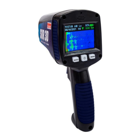
Decatur Electronics Scout 2 User manual

Scout 2
User’s Manual
Rev 12/15/2021
This manual intended for use in Canada only

2
Welcome to Decatur Electronics
Thank you for choosing this Decatur Electronics product — A highly advanced
trac radar unit that will reward your department with years of dependable
service. The Scout 2 incorporates high performance and long range, with
many leading features. We urge you to study this manual before using the
Scout 2 so you can maximize the benets of this sophisticated radar device. We
believe you will be pleasantly surprised by the features and advantages.
If you are as pleased with its performance, as we think you will be, ask your
Decatur sales representative about other Decatur products including the
Genesis G3 line of radars, and the OnSite line of speed trailers, dollies, and pole
signs.
Trac ocers told us exactly what they wanted in a radar device - and we built
it!
—The Management and Sta at Decatur Electronics,
The Nation’s Oldest Radar Company

3
About This Manual
This manual contains valuable information to help you set up, use and maintain your radar. Please take a moment to
read through it, and keep it handy for future reference.
Note the following symbols in this manual:
Indicates a helpful tip or precaution to note.
Safety Information
All service needs should be referred back to the manufacturer or a factory authorized service centre.
• Opening the Scout 2 automatically voids any warranty still in eect. There are no user serviceable parts inside.
• Do not submerge the Scout 2. If the device should accidently get submerged contact your factory authorized
service centre immediately!
• Do not drop the Scout 2 on hard surfaces since damage could occur. Units damaged by dropping or abuse are
not covered for warranty repair.
Violation of these guidelines may void the warranty.
Receiving Inspection
• When you receive your radar, inspect all components for damage that might have happened during shipping.
• Notify the shipping company immediately of any damage. Take pictures to document any damage.
• The package should include a USB-C charging cable along with the radar.

4
Introduction
The Scout 2 is a stationary radar that gives you the option to track vehicles that are approaching, receding, or moving
in either direction simultaneously. Directionality dramatically enhances the target selection process. For example,
if the radar is set in toward mode (down arrow), it will track only vehicles coming toward the radar and ignore all
vehicles moving away from it! On a road with bidirectional trac, you can choose to make trac moving in either
direction invisible to the radar.
Battery Charging
The Scout 2 is designed to primarily operate o of its internal battery pack and recharges from a ubiquitous type A
USB port. For the fastest recharge time, use only the Decatur Electronics recommended USB cable and charger.
When you receive your radar, the batteries will need to be charged for the rst time. Additionally, if the radar has
been stored for an extended period of time, you will want to recharge the batteries as well. A fully charged radar
should run for approximately 1 week between charges given normal use. To charge the batteries follow steps below.
• Connect the power cord to the USB-C receptacle on the bottom of the radar.
• Plug the radar’s power cord into your vehicle’s USB receptacle or A/C USB adapter.
• Charge Status Indicator.
Battery charging status can be determined two ways depending if the radar is on or o.
Radar O: When plugged into a powered USB port, the Power/Fast button will glow green when charging.
When the batteries are fully charged the green LED will go out.
Radar On: When plugged into a powered USB port, the battery charge icon will change to a charging icon.
The radar can be left to charge indenitely. The charging will automatically shut o once the batteries are fully
charged.
Operating the radar whiles charging
The radar may be operated while the batteries are recharging. The radar automatically switches from the internal
batteries to the power cord for power when the unit is turned on and will also recharge the batteries at the same time.
The batteries are not user serviceable. The batteries are designed to provide more than 70% of their
rated capacity after 500 charge/discharge cycles. If you are experiencing short run times between
charging, contact your factory authorized service centre for battery replacement.

5
Scout 2 Controls and Display
Controls
The operation of the Scout 2 is controlled by the three-button key pad and the trigger.
TEST When you press the TEST button, the radar runs a comprehensive self test.
FAST / Power If the radar is o, pressing the FAST/Power button will turn it on. To turn the radar o, press and
hold the Fast/Power button until the powering down message is displayed then release.
If the radar is on, a short press of the Fast/Power button will toggle between Strong and Fast modes.

6
MENU The MENU button lets you view the options you can change. Repeatedly pressing the MENU button
advances through the list of features.
Trigger If you are not in menu mode, pressing the trigger activates the radar transmitter and releasing it stops it. If
you are in menu mode, repeatedly pressing the trigger advances through the menu item settings.
To measure the speeds of target vehicles, pull and hold the trigger. If you want to lock a speed,
release the trigger then quickly pull it again (within 1/2 second). As long as you continue to hold
the trigger, the radar will continue to track targets and display their speeds. The locked speed clears
when you pull the trigger again.
Radar Display
Display Zones
The Scout 2 uses a black and white display. The display is divided into an upper information zone and a lower speed
zone.
Information Zone
The information zone of the display will show :
Hold / Xmit When radar is transmitting it will show Xmit otherwise it will show Hold.
RFI The radio frequency interference message indicates that excess RFI energy is present. When active, the radar
automatically inhibits all speed measurements and no speeds will be displayed. When the RFI condition no longer
exists, the radar will resume normal operation.

7
KPH The radar displays speed in kilometers per hour (KPH).
BATTERY LIFE Battery life is shown by the percentage of life left and by a graphical battery icon.
LOW BAT The LOW BAT icon indicates that your battery pack is low on power. The system will not transmit or
display any new speeds while LOW BAT appears, and if the system is displaying a locked speed, the speed will remain
displayed.
ERROR ERROR shows that the radar has detected an internal hardware error which can aect the proper operation
of the radar device. You should turn the radar o and back on. If the problem persists, contact Decatur Electronics at
800-428-4315 or your local factory authorized service centre for assistance.
Speed Zone
In the lower speed zone, the radar will display one or two speed readings and the associated direction of travel.
When operated in Strong mode one speed is shown.
.
When operated in Fast mode, two speeds are shown. The upper speed is the Fast speed and the lower one is the
Strong speed.

8
If you lock a speed while in Fast mode, the locked speed replaces the Fast speed.
Changing the radar settings
By using the menu feature, you can review and change many of the radar's settings. The radar will remember the
settings you last set when it is turned o and will power up with them.
Menus
The most commonly adjusted settings, Direction, Range and Volume are presented graphically. All other settings are
found in a secondary menu represented by the gear icon.
To change a setting, repeatedly press the MENU button until the icon representing the setting you
want to change appears. Then press the trigger switch to advance through the selections for that
setting. When you have made your selection, your new settings will be in eect immediately. If
neither MENU or the trigger switch is pressed after 2 seconds, the radar will return to normal
operating mode. You may also exit the menu setting by selecting the Exit icon.
Direction
The direction icon lets you select the direction of the target vehicle you want to display. An
up/down arrow indicates that you are monitoring vehicles moving both toward and away
from the radar.
Range
The range icon lets you control the maximum target-acquisition range in 5 steps. The
number of wavelets in the icon change based on the range selected. 1 is the lowest, 5 is
maximum. You will normally want to start with the maximum range and decrease it until you
attain the desired performance level.
Volume
The Volume icon controls the volume level of the Doppler tone. The volume level settings are
from 1 to 5. The operator cannot mute audio.

9
Secondary Menu
The secondary menu (gear icon) allows you to make adjustment to less common settings.
In this menu you will nd:
Squelch
The squelch determines the type of Doppler audio you want. When squelch is on, the sound is only the Doppler tone
for the displayed target. When squelch is o, you will hear all Doppler tones, including other vehicles, interference
and any noise the antenna receives. Normally you operate the radar with the squelch setting to ON.
Dimmer
This controls the display brightness. It can be set to AUTO to automatically adjust to ambient lighting or xed at one
of eight preset levels. Level 1 is the dimmest and level 8 is the brightest.
Beep
This option lets the radar to give an audible “beep” to verify every time a key is pressed.
Units
This radar calculates and displays speeds in kilometers-per-hour (KPH) only and cannot be changed.
COM (Serial)
This sets the serial communication protocol to one of several options.
Auto shutdown
This option is designed to maximize battery life by automatically turning the radar o after a set period of time when
the radar has not been used. You can choose between 3 shutdown periods (5 min., 10 min., 15 min.) or disable it by
setting it to OFF.
RADAR PROCESSING MODES
Directionality
You can change the direction selection to measure the speeds of targets coming toward you, or display only the
speeds of targets moving away from you, or both directions at the same time. When you are in bidirectional mode,
the radar will display a up or down arrow on the right hand side of the display depending on the direction the target
is traveling.
The radar lets you easily select and focus on vehicles approaching or receding from your position.
As an example, while in towards mode (down arrow), the radar does not track the truck going away
at 88 KPH as pictured, rather displays the car going towards the patrol vehicle at 98 KPH.

10
Strongest Signal Mode
All radars track the strongest signal since this is an essential element of tracking history. The radar defaults to the
strongest signal-tracking mode and will stay in this mode until you press the FAST button. In Strongest Signal
tracking mode, the radar displays the speed of the vehicle with the strongest return signal, which is often the closest
vehicle.
Faster Mode
The advanced signal processing algorithms in the Scout 2 simultaneously track multiple vehicles. In FAST mode, the
radar displays the speed of the strongest vehicle and a faster vehicle at the same time. To determine which is the
faster vehicle, the radar takes the strongest return signal and uses it as a reference level. It then looks at the return
signal levels from all other vehicles going faster than the strongest vehicle and compares them to that reference
level. It will display the speed of the vehicle that is moving faster than the strongest signal and is the next strongest
target. In multiple target situations, the next strongest target going faster than the strongest is often closest to the
strongest vehicle.
In the example below, the semi going 99 is the strong target and the overtaking vehicle going 123 is the Fast target.
The vehicle going 136 is ignored since it is not the next strongest target.
To switch from Strongest Signal target to Faster target, press and release the FAST button. The system will remain in
Faster mode until you press the FAST button again or until you lock a speed, which automatically switches the radar
back to the Strongest Signal Mode.
In Fast mode, the radar gun locks only the strongest vehicle speed.
Performance Tips
Understanding potential radar interference and what to do when it occurs can greatly increase the radar’s
performance.

11
How Radar Works
Determining a vehicle’s speed begins with the radar transmitting a beam of microwave energy (radio waves) at a
target vehicle. When energy from this beam strikes a vehicle, a small amount of the energy is reected back to the
antenna. The frequency of the reected energy shifts by an amount proportional to the speed of the target vehicle.
This is known as the Doppler eect. The radar device then determines the target vehicle speed from the dierence in
frequency between the reected and transmitted signal.
Interference Sources
When properly installed and operated, a Doppler radar is extremely accurate and reliable. However, variations in the
environment can cause situations and circumstances which can cause spurious (erratic and unusually low or high)
speeds to display. Signs that a speed is spurious can include the following characteristics:
• A reading appears when no target vehicle is in the operational range of the antenna.
• A target vehicle entering the operational range overrides the interference signal, causing the display speed to
change suddenly to the correct vehicle’s speed.
• The Doppler tone is corrupted with noise.
• Speeds are irregular and do not provide a valid trac history.
• Erroneous speeds appear to track changes with the engine rpm.
Angular Interference (Cosine Error Eect)
The cosine eect causes the system to display a speed which is lower than the actual vehicle speed. This condition
occurs when the target vehicle’s path is not parallel to the antenna, including conditions such as the vehicle traveling
on a curve or hill.
As the angle between the beam of the antenna and the target vehicle increases, the displayed speed decreases.
Ideally, an angle of zero (0) degrees is preferable, because the displayed speed is the actual target vehicle speed.
However, in all uses of police radar, the radar device is always at a slight angle to the target vehicle to avoid collisions.
Velocity
Vector
Angle
Radar
An angle between the antenna and the target vehicle causes the cosine
eect

12
The following table shows the eect that an increasing angle has on a displayed speed.
Horizontal Angle Degrees
Actual
Speed
0° 1° 3° 5° 10° 15° 20° 30° 45° 60° 90°
Displayed speed:
50 km/h 50 49 49 49 49 48 46 43 35 25 0
65 km/h 65 64 64 64 64 62 61 56 45 32 0
80 km/h 80 79 79 79 79 77 74 69 56 40 0
90 km/h 90 89 89 89 88 86 84 77 63 45 0
100 km/h 100 99 99 99 98 96 93 86 70 50 0
110 km/h 110 109 109 109 108 106 103 95 77 55 0
Actual and displayed speeds at antenna-to-target angles
Small angles (less than 10°) have little eect on accuracy. As the angle increases, the displayed speed decreases. At
90° the radar reads the speed of the object as zero regardless of it's true speed.
Fan Interference
Fan interference is the most common form of interference that you are likely to experience. It is caused when the
radar measures the speed of the vehicle blower fan. Changing the fan speed causes a proportional change in the
display speed. To correct this, relocate the radar so it does not display spurious speeds or turn o the blower fan
motor.
Electromagnetic Interference (EMI)
Operating electric motors can produce EMI. EMI from power seats or windshield wipers can also produce spurious
target speeds. To correct the interference, simply turn o its source.
Feedback Interference
When the radar beam is directed at computer screens, streetlights, and other electronic devices, it can display
spurious speeds. To correct the interference, relocate the radar.
Multi-Path Beam Cancellation
If multi-path beam cancellation occurs, the target vehicle speed sporadically blinks and reappears at semi-random
intervals. This type of interference occurs when the radar loses track of a target vehicle because the target is
reecting two or more signals, which are interfering with each other. The Scout 2 is immune from multi-path
cancellation.
Radio Frequency Interference (RFI)
The system can inadvertently process radio energy as Doppler speeds, including that from police radios, airport radar,
microwave transmission towers, CB radio transmitters, and AM/FM transmission towers. For this type of interference
to occur, the radar must be operating very close to the radio transmitter.
The Scout 2 radar contain an RFI detection circuit that detects excess radio frequency energy. When stray radio
frequency energy reaches an excessive level, the system displays an RFI message and stops processing and displaying
speeds. The system resumes normal operation when the RFI condition no longer exists. At that time, any locked
speeds will display again.

13
Scanning
The Scout 2 is designed to be hand-held in a steady position. Moving or “scanning”the antenna past stationary
objects can cause the system to detect motion. Obtaining a speed reading from scanning will not happen when you
properly use the radar and this considered deliberate misuse of the system.
Vehicle Ignition Interference
The Scout 2 has been designed to operate from their internal battery pack but can be powered from the vehicle’s USB
receptacle. When connected to the USB receptacle it should be noted that some vehicles exhibit excessive alternator
noise at the USB receptacle. In these rare cases, the radar can exhibit erratic readings, especially when the vehicle’s
electrical system is operated under heavy load. Wiring an accessory USB outlet directly to the battery minimizes the
eect. If you are operating o of the radar’s internal batteries, then vehicle ignition interference will not be a factor.
If you suspect that there is an interference with your vehicle’s electrical system, contact local Decatur Electronics
factory authorized service centre for more information.
Testing the Device
Operator-Initiated Self Test
Pressing the TEST button starts a comprehensive system self test, which allows the operator to verify the display and
runs a target speed simulation. The self test includes:
Display Test–The display test veries that the digits and status icons are working correctly and that none of the
pixels in the number segments are damaged.
Circuitry Test–The system checks the internal circuitry. If the unit passes all internal checks, the message PASS will
be displayed. If an error should occur then FAIL will appear in the display window.
Speed Simulation Test–The radar veries speed accuracy using synthesized Doppler frequencies corresponding
to a series of four simulated speeds: 40, 70, 100, and 130 KPH.
If the device does not display the expected speed, contact your local Decatur Electronics factory authorized
service centre at 800.428.4315 to arrange for service.

14
Mounting Congurations
The radar is designed primarily for hand-held operation. Optionally, you can mount it to a standard camera tripod.
Contact your local distributor for the tripod mounting kit.
Care, Cleaning, and Storage
• Avoid spilling food, beverages and other liquids on the radar device.
• When you are not using or transporting the device, store it in its original packaging or approved case.
• To clean the radar device, dust it with a soft clean cloth, which is free of cleaning solutions.
Frequently Asked Questions (FAQ)
Q. My radar will not power up. What should I do?
A. Check to make sure the batteries are charged. If operating o the power cord, then check to make sure that the
power cord is properly plugged into the power source. If your radar still does not power up, call your local Decatur
Q. My radar has poor range. How can I remedy this?
A. Verify that the antenna has no obstructions in front of it. If the radar still has poor range, increase the range level.
If you still have this problem, contact Decatur Electronics.
Q. Will my radar work while my vehicle is moving?
A. No, the Scout 2 radar is a stationary only model, so your vehicle should be stationary.
Q. What if I drop my radar?
A. The unit is extremely durable. Simply power up and perform the self test. If the radar doesn’t appear to work
properly, contact your local Decatur Electronics factory authorized service centre.
Service & Repairs Procedure
If you have questions, concerns or need a quick problem diagnosis, please reach out to your Customer Service
Representative:
• Call Decatur Electronics by phoning 800.428.4315 and ask to speak with a Customer Service Representative.
• Explain to the Customer Service Representative the problem you are experiencing.
• Based on the information that you provide, the Customer Service Representative may be able to assist you or you
may need to be referred to one of our Service Providers.
If and after a Decatur Service Representative has diagnosed the items, Decatur Electronics will allocate the service
Ticket to an Authorized Service Centre.
For in warranty items, the repair will be performed and the items,shipped back to you in a timely manner (if you want
the package shipped express or next day air, there will be a charge).
For items not under warranty Decatur Electronics will refer you to an Authorized Service Centre, who will provide
you with an estimate for the repair. Decatur Electronics will not assume the repair charges for units that are out of
warranty or for service work performed on warranty units when that work is not warranty related.
THREE-YEAR RADAR WARRANTY
Decatur Electronics guarantees the radar to be free from defects in workmanship and material and to operate
within specications for a period of three (3) years. During this period, Decatur Electronics will repair or replace,

15
at its option, any component (excluding the USB charging cable) found to be defective, without cost to the owner,
providing you return the unit to a Decatur authorized warranty service centre. The full warranty on parts and
workmanship does not include normal wear and tear, crushing, dropping, re, impact, immersion, over-tightening of
screws or damage from attempted repair or modications by unauthorized service agents.
THREE-YEAR WARRANTY EXCEPTION
If the unit was purchased under a special buying program (federal and provincial purchase contract, non-standard
warranty terms, etc.), then the above warranty may not apply. Please refer to the buying schedule contract for the
appropriate warranty terms or contact Decatur Electronics' Customer Service Representative at 800-428-4315 or

16
Specications
Antenna Parameters
K-Band
IACP Type III
Nominal transmission frequency 24.150 GHz
Nominal horizontal beamwidth 12° H 24° V
Polarization Linear (Vertical)
Nominal microwave power output 7 mW
Maximum aperture power density <1 mW/cm2
Environment
Ambient operating temperatures -30ºC to +60ºC
Maximum humidity 90% relative humidity (non-condensing) at 37°C
Speed Range Parameters
Speed Display Ranges (KPH) Minimum Maximum
20 337
Power Consumption Parameters
Supply voltage range 4.5VDC – 5.5VDC
Battery Low Voltage Trip with antenna ON 6.0 VDC (measured at internal battery)
Current draw when using power cord
All currents are nominal and measured at 5.0 VDC with fully charged batteries, backlight at 8 and speaker volume at
4.
Antenna OFF (Standby) 0.31 amperes
031 amperes (segment check“888 888”)
Antenna ON (Transmit) 0.40 amperes (no targets displayed)

17
ISED Information
This device contains license-exempt transmitter(s)/receiver(s) that comply with Innovation, Science and Economic
Development Canada’s license-exempt RSS(s). Operation is subject to the following two conditions:
(1) This device may not cause interference.
(2) This device must accept any interference, including interference that may cause undesired operation of the
device.
Caution: Any changes or modications not expressly approved by the party responsible for compliance could void
the user’s authority to operate this equipment.
Industry Canada Regulatory Information
CAN ICES-3 (A)/NMB-3 (A)
Cet appareil contient des émetteurs / récepteurs exemptés de licence conformes aux RSS (RSS) d'Innovation, Sciences
et Développement économique Canada. Le fonctionnement est soumis aux deux conditions suivantes:
(1) Cet appareil ne doit pas causer d'interférences.
(2) Cet appareil doit accepter toutes les interférences, y compris celles susceptibles de provoquer un fonctionnement
indésirable de l'appareil.
Attention: Tout changement ou modication non expressément approuvé par la partie responsable de la conformité
peut annuler le droit de l'utilisateur de faire fonctionner cet appareil.
Avis d’Industrie Canada
CAN ICES-3 (A)/NMB-3 (A)
ISED Radiation Exposure Statement
This equipment complies with ISED radiation exposure limits set forth for an uncontrolled environment. This
equipment should be installed and operated with minimum distance 20 cm between the radiator and your body.
Déclaration d'exposition aux radiations Cet équipement est conforme aux limites d'exposition au rayonnement ISED
établies pour un environnement non contrôlé. Cet équipement doit être installé et utilisé à une distance minimale de
20 cm entre le radiateur et corps.

www.DecaturElectronics.com
800.428.4315
Table of contents
Other Decatur Electronics Measuring Instrument manuals
Popular Measuring Instrument manuals by other brands

Aquametro
Aquametro AMTRON X-50 Mounting and operating instructions

Asahi KASEI
Asahi KASEI AK4493 manual

B meters
B meters HYDROCAL-M4 Operating and installation instruction

Technoline
Technoline WL 1030 instruction manual

TScale
TScale RWP Technical manual

red lion
red lion APOLLO IMS Series instruction manual