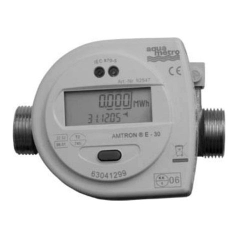
Aquametro AMTRON X-50 Service manual

Mounting and operating instructions
M10000def.doc
AMTRON R
X-50 Serie-Nr.
BMEE [Internet version]
M10630def
Please help to ensure a long reliable service of this heat meter by carefully installing it according to the instructions.
These instructions are to be given to the user or leave them near the device!
M10720def
November 9, 2006
VD 3-248 e 03.2006

Mounting and operating instructions AMTRON R
X-50
Contents
Intendeduse ................. 3
Installation instruction . . . . . . . . . . . . . . . 3
View of the unit . . . . . . . . . . . . . . . . . 8
Operating instructions . . . . . . . . . . . . . . . 9
Display ................. 9
Operating modes . . . . . . . . . . . . . . . . 9
Explanations .................10
Mainloop..................11
INFO loop (Information) . . . . . . . . . . . . . . . 12
Instantloop .................12
Timeloop..................13
Stich loop (billing date) . . . . . . . . . . . . . . . 13
Loggerloop .................14
Inputsloop .................14
Unitsloop..................16
M-Busloop .................18
CONFIG loop (Configuration) . . . . . . . . . . . . . . 18
Systemloop .................20
Editing methods . . . . . . . . . . . . . . . . 20
Number entry . . . . . . . . . . . . . . . . 20
Dateentry.................21
Timeentry.................21
Commissioning . . . . . . . . . . . . . . . . 21
Function control . . . . . . . . . . . . . . . . 21
Error messages, alarms . . . . . . . . . . . . . . . 22
Databack-up ................. 22
Recalibration/auditing . . . . . . . . . . . . . . . 22
Procedure.................22
Audit modules . . . . . . . . . . . . . . . . 23
Technical data . . . . . . . . . . . . . . . . . 23
Mounting template . . . . . . . . . . . . . . . . 27
VD 3-248 e 03.2006 2 Aquametro AG

AMTRON R
X-50 Mounting and operating instructions
Intended use
The device is to be used in dry interior areas. For applications in Ex areas or in contact with water or other liquids no
liability can be assumed.
Installation instruction
The installation may only be carried out by authorised experts in accordance with valid regulations (EN1434 Part 6 Reg-
ulations and Recommendations for Installation and Operation) and/or the recommendations of specialist organisations
(such as the AGFW series Codes of Practice for District Heating.
Important:
The totaliser, the paired sensors and the flow meter of a measuring point are to be compatible with one another
and should not be replaced.
Verified instruments are lead sealed. These seals should not be damaged or broken in any way.
Measuring instruments have to be treated with caution. To protect from damage and contamination, the packing should
be removed just before installation.
Verify, if the sensor (e.g. Pt500) is suitable for the calculator. Pay attention to the correct installation side (warm
side, cold side) of the flow meter.
Verify the pulse value of the flow meter and the totaliser according to the labels. Pay attention to the flow direction
of the flow meter.
Verifiable parameters or other service parameters can only be changed in the field if the instrument is not a verified unit.
Documentation is available on request.
Aquametro AG 3 VD 3-248 e 03.2006

Mounting and operating instructions AMTRON R
X-50
Scope of supply; needed mounting material and tools
1) Option
M0210def.doc
M0220def.doc
Open casing
M0240def.doc
VD 3-248 e 03.2006 4 Aquametro AG

AMTRON R
X-50 Mounting and operating instructions
Mounting on DIN rail (Mounting template, see attachment)
M0280def.doc
Mounting on flat wall (Mounting template, see attachment)
M0260def.doc
Aquametro AG 5 VD 3-248 e 03.2006

Mounting and operating instructions AMTRON R
X-50
Terminal assignments see inside cover
M0300def.doc
Terminal assignments
M0600def
VD 3-248 e 03.2006 6 Aquametro AG

AMTRON R
X-50 Mounting and operating instructions
Connect signal cables and where appropriate connect the low voltage supply
M0330def.doc
Close cover Remove sealing studs
M0710def.doc
M0730def
These instructions are to be given to the user or leave them near the device!
Aquametro AG 7 VD 3-248 e 03.2006

Mounting and operating instructions AMTRON R
X-50
View of the unit
0. Cover
1. Liquid Crystal Display (LCD)
2. Enter key
3. Select key
4. Sight glass, if verified with calibration mark
5. Optical M-Bus interface
6. Service key
7. Programming key under seal
8. Nameplate of totaliser module
9. Cover screws (under sealing studs)
10. Mounting holes
11. Clip-on holder for rail mounting
12. Cover hinge
13. Plug-in totaliser module
14. Connector module
15. Cable entry Ø12 mm with plastic seal
16. Cable entry Ø16 mm with plastic seal
17. Options module
M0770def
M0785def
M0790def
VD 3-248 e 03.2006 8 Aquametro AG

AMTRON R
X-50 Mounting and operating instructions
Operating instructions
Display
M0850def.doc
1. Tag, 3 characters
2. Numerical display with 8 large characters
3. Decimal point numbers are highlighted within a frame
4. Units
5. Unit in User Mode
6. Unit in Service Mode
7. Edit Mode: displayed values can be altered
8. Alarm
9. No function
10. Flow display, flashes when flow is registered
11. Symbol for values in memory (billing date or logger)
12. Select key
13. Enter key
Operating modes
With the operating keys all relevant settings (depending the Operating mode) to be carried out.
User Mode:
When the housing is closed, freely accessible data can be shown in the display using the keys. Service Mode:
This can be activated by pressing the service key when the cover is open. It also enables all necessary but non-verifiable
start-up parameters to be set and displayed.
Programming Mode:
This can be activated only if the factory seal has been destroyed. This enables the complete range of settings, including
calibrated values to be made.
Aquametro AG 9 VD 3-248 e 03.2006

Mounting and operating instructions AMTRON R
X-50
Explanations
Edit
Prog
E 12345678 kWh
INFO
E 12.345678 kWh
E 12345.678 kWh
Memory
S-Edit
P-Edit
Prog
M0900def
Press Select key
Press Enter key
Press Service key
Press Programming key (under seal)
Unit in User Mode
Unit in Service Mode
Unit in Program Mode, only possible if the seal is
destroyed
Example for a display
Display under certain conditions
Unit in Edit Mode
Display of logger data and billing readings
Press Select and Enter keys simultaneously:
3 more decimal places will be shown
Edit in Service Mode:
- Press Service key
- Press Enter key
- Entry according to type of data
Edit in Programming Mode:
- Press Service key
- Press Enter key
- Entry according to type of data
VD 3-248 e 03.2006 10 Aquametro AG

AMTRON R
X-50 Mounting and operating instructions
Main loop
The main loop shows the most important readings and provides access to subloops.
High accurate readings can also be displayed when both keys are pressed simultaneously.
The meter readings of the calculator can be adjusted to external counters in Service- or Program-Mode. Changes in
Program-Mode can only be changed if the instrument is not a verified unit.
H2 12345 .678 m3
H3 12345 .678 m3
ImP 100 L
Sid cold
INFO
InStAnt
tIME
Stich
LOGGEr
InPutS
OutPutS
UnitS
M-bUS
CONFIG
SYStEM
E 12345678 kWh
V 12345678 m3
LCD
Test
/
/
S-Edit
P-Edit
/
P-Edit
/
S-Edit
M0960def
Energy
Volume
Auxiliary meters 2
Auxiliary meters 3
Pulse value
Installation side
Error messages
Display test
Instantaneous values
Time parameters
Billing date
Logger data
Input signal parameters
Output signal parameters
Units
M-Bus parameters
Configuration parameters
Manufacturing parameters
Aquametro AG 11 VD 3-248 e 03.2006

Mounting and operating instructions AMTRON R
X-50
INFO loop (Information)
Errors or alarms are shown in the INFO loop. These are only shown if the trigger status is reached.
Errors have to be fixed. Alarms are shown as long as they are present.
th-ERROR
tc-ERROR
INFO
th-ALArM
tc-ALArM
SYSt-Err
dt-ALArM
M1060def
Sensor error on hot side
Sensor error on cold side
Error in totaliser
Temperature on hot side out of measuring range
Temperature difference out of measuring range
Instant loop
The Instant loop shows the current values.
Th 60.0 °C
Tc 40.0 °C
InStAnt
∆T 20.00 °C
P 0.025 MW
Q 6.5 m3/h
KF 1.156
DEN 0.991 KG/L
M1120def
Temperature on hot side
Temperature on cold side
Temperature difference
Power
Volume rate
C-Factor
Density of fluid
VD 3-248 e 03.2006 12 Aquametro AG

AMTRON R
X-50 Mounting and operating instructions
Time loop
Time relevant data can be displayed and adjusted.
DAT 01.06.03
TIM 08:15
tIME
Hr 1234 h
Err 0 h
SEA WintEr
St1 30.06.--
St2 31.12.--
S-Edit
S-Edit
S-Edit
S-Edit
S-Edit
M1160def.doc
Date
Time
Operating hours
Hours of error
Summer- or wintertime
Billing date 1
Billing date 2
Stich loop (billing date)
Display the memorised billing dates 1 or 2 .
Note: Billing dates can be set in the Time loop.
Memory
Nr. 2
Stich
Memory
Err 0 h
Memory
DAT 01.07.03
Memory
E 12345678 KWh
Memory
H2 12345.678 m3
Memory
H3 12345.678 m3
Memory
V 12345.678 m3
Memory
Nr. 1
M1240def
Memory number
Date of billing
Energy reading on billing date
Volume flow reading on billing date
Reading of auxiliary counter 2 on billing date
Reading of auxiliary counter 3 on billing date
Hours of error till billing date
Aquametro AG 13 VD 3-248 e 03.2006

Mounting and operating instructions AMTRON R
X-50
Logger loop
This operating loop enables values in the data logger to be read.
Note: The logging intervals can be set in Service-Mode [S-Edit] in the display PER.
Memory
Nr. 2
LOGGEr
Memory
Nr. nn
Memory
PER Month
Memory
E 12345678 KWh
Memory
V 12345678 m3
Memory
H2 12345678 MWh
Memory
H3 12345678 MWh
Memory
P 0.032 KW
Memory
Err 0 h
Memory
PER InActive
Memory
DAT 01.07.03
Memory
Nr. 1
S-Edit
S-Edit
M1340def
Selection of memory file (1 … 31)
Period of billing
Date of capture
Energy reading on capture date
Volume flow reading on capture date
Reading of auxiliary counter 2 on capture
date
Reading of auxiliary counter 3 on capture
date
Maximum power during capture period
Hours of error during capture date
Memory
PER Month
Memory
PER InActivE
Memory
PER Month
Memory
PER 2 dAY
Memory
PER 1 dAY
Memory
PER Hour
M1410def.doc
Inactive, no logging
Monthly logging
Logging every two days
Daily logging
Hourly logging (not for battery calculator)
Inputs loop
Remove the totaliser module and check that option board is correctly mounted and that the selector switch(es) is/are
set to Position "In". Carry out the settings of the pulse input.
The adjustments of the auxiliary inputs (No. 2 and No. 3) have an effect only if they are physically available.
The auxiliary inputs (No. 2 and No. 3) can be set in the Service Mode [S-Edit] .
Note: Before adjusting the pulse value, you have to choose the unit in the units loop.
Settings of the main input (No.1) are verifiable. They can only be changed if the seal is broken [P-Edit].
VD 3-248 e 03.2006 14 Aquametro AG

AMTRON R
X-50 Mounting and operating instructions
Data in a grey field will not be displayed in User-Mode.
Nr. 3
Nr. 2
InPutS
Fct VOLUME
Sid cold
F 10 Hz
STA ON
MAX 153.0 °C
MIN 0.0 °C
ImP 1.000 L
Nr. 1
P-Edit
P-Edit
M1480def
Input number (1)
Volume impulse
Pulse value
Installation side of the flow meter
Maximum input frequency
ON: Contact closed
Off: Contact open
Permissible maximum temperature
Permissible minimum temperature
Sid cold
Sid hot
Sid cold
M1500def.doc
Built in cold side
Built in warm side
Nr. 1
Nr. 3
InPutS
Fct HELP
F 10 Hz
STA ON
ImP 1.000 L
Nr. 2
S-Edit
M1540def
Input number (2 & 3)
Auxiliary input
Value of a pulse
Maximum input frequency = 10Hz
ON: Closed contact
Off: Open contact
Aquametro AG 15 VD 3-248 e 03.2006

Mounting and operating instructions AMTRON R
X-50
Units loop
It is possible to choose the presentation of the variables (units and number of decimal places) in the Units loop.
IMPORTANT:
These settings apply to all pulse in- and outputs. They limit the option for setting the pulse value (see Input loop)
E 1 KWh
V 0.01 m3
UnitS
H2 1 HCA
H3 1 HCA
P MW
Q m3/h
P-Edit
P-Edit
S-Edit
S-Edit
S-Edit
T °C
EP Pro PULS KWh
VP Pro PULS L
S-Edit
S-Edit
P-Edit
S-Edit
M1970def.doc
Unit and decimal places of the display
Unit of the power display
Unit of the flow rate display
Unit of the temperature display
Unit of the energy pulse
Unit of the volume pulse
M1980e
0.001, 0.01, 0.1, 1 kWh
0.001, 0.01, 0.1, 1 MWh
0.001, 0.01, 0.1, 1 MJ
0.001, 0.01, 0.1, 1 GJ
0.001, 0.01, 0.1, 1 KBT=kBtu
0.001, 0.01, 0.1, 1 MBT=MBtu
E 1 KWh
M2000def.doc
Possible settings
0.001, 0.01, 0.1, 1 m3
0.1, 1 GAL=USgal
V 0.01 m3
M2020def.doc
Possible settings
VD 3-248 e 03.2006 16 Aquametro AG

AMTRON R
X-50 Mounting and operating instructions
0.001, 0.01, 0.1, 1 kWh
0.001, 0.01, 0.1, 1 MWh
0.001, 0.01, 0.1, 1 MJ
0.001, 0.01, 0.1, 1 GJ
0.001, 0.01, 0.1, 1 m3
0.1, 1 GAL=USgal
H1, 2, 3 1 HCA
1 HCA
0.001, 0.01, 0.1, 1 t
0.001, 0.01, 0.1, 1 KBT=kBtu
0.001, 0.01, 0.1, 1 MBT=MBtu
M2040def.doc
Possible settings
KW
MW
MJ/h
GJ/h
KB/h=kBtu/h
MB/h=MBtu/h
P MW
M2070def.doc
Possible settings
m3/h
GA/h=USgal/h
Q m3/h
M2080def.doc
Possible settings
°C
°F
T °C
M2090def.doc
Possible settings
KWh
MJ
KBT=kBtu
EP Pro PULS KWh
M2100def.doc
Possible settings
L
GAL=USgal
m3
VP Pro PULS L
mL
M2110def.doc
Possible settings
Aquametro AG 17 VD 3-248 e 03.2006

Mounting and operating instructions AMTRON R
X-50
M-Bus loop
The following variables are shown or set in the M-Bus loop:
Adr 0 ... 250
M-bUS
Nr 1 bAud 2400
Nr 2 bAud 2400
Ac1 0...255
S-Edit
S-Edit
Ac2 0...255
S-Edit
M2160def
Primary M-Bus address
Baud rate for M-Bus (function, when card is present)
Baud rate for M-Bus (Opto & M-Bus #2 card)
Number of accesses over M-Bus 1
Number of accesses over M-Bus 2
M2170e
bAud 300
bAud 2400
Nr 1, 2 bAud 2400
M2180def.doc
Possible baud rates
M2190e
CONFIG loop (Configuration)
The following variables are shown or set in the configuration loop:
SMU 1.55 K/°R
CONFIG
Rem 60 s
Ftr 1
Loc USEr
S-Edit
S-Edit
S-Edit
RES CANCEL S-Edit
S-Edit
M2240def.doc
∆T, low flow cut off
Rem = time of display of instantaneous values
Filter-number (0 … 20)
Activated operating mode (lock level)
Reset of alarms and counters
M2250e
0 ... 2.99 K/°R
SMU 1.55 K S-Edit
M2320def.doc
Temperature difference below which no further energy is
counted.
The unit for ºC is K and for ºF it is ºR
M2330e
VD 3-248 e 03.2006 18 Aquametro AG

AMTRON R
X-50 Mounting and operating instructions
8 ... 240 s
Rem 60 s S-Edit
60 ... 240 s
M2340def.doc
Rem = time of display of instantaneous values (flow,
power) after reception of the last impulse (in s) . If
the time between two pulses is exceeded then the
present values are shown as 0.
8 … 240 s for a mains totaliser and
60 … 240 s for a battery totaliser
M2350e
0 ... 20
Ftr 1 S-Edit
M2360def.doc
Filter value for the calculation of the current value
M2370e
The higher the value, the higher the delay time Tv for the average calculation.
Larger Tvs are to be set if the input pulses are received at irregular intervals, otherwise the flow display will
fluctuate too much.
Approximation formula:
Tv = (Filter value +1)*5* cycle time (20 s for battery version, 1 s for mains version).
USEr
SErvICE
Loc USEr
ProGrAM
M2390def
No settings possible
No settings for verifiable parameters
Verifiable parameters are adjustable
M2400e
Possibilities User Service Program
No
Non verifiable data X X
All parameters — X
M2405e
CANCEL
ALArM
RES CANCEL
CountEr
M2410def.doc
Reset of alarms and counters according the
authorization in the table below
M2420e
Mode User Service Program
Cancel X X X
Reset Alarm X X
Reset Counter X
M2430def
Aquametro AG 19 VD 3-248 e 03.2006

Mounting and operating instructions AMTRON R
X-50
System loop
The following values can be displayed in the system loop:
FNr 12345678
SYStEM
SYS H-50
DAT 18.12.05
FW 1.05.00
HW 2.01.10.00
M2500def.doc
Fabrication No. of the instrument
Version of the device
Date of manufacture
Firmware version
Hardware version
M2510e
Editing methods
The following examples show the editing methods in Service mode [S-Edit].
For non calibrated totalisers it is possible to adjust values, digits and sign (+/-) in Program mode [P-Edit] too.
Number entry
If it is possible to adjust a (multi-) digit in an operating loop, then follow the procedure in the graphic bellow:
ImP 1.000 kWh
S-Edit
ImP 0001.0001
ImP 0001.000 2
ImP 0001.000 7
M2560def
Activate Service Mode with Service key
Press Enter key to enter in Edit mode
Adjust the digit (1) with the Select key
Change to next digit (2) with the Enter key
Adjust the digit with the Select key
:
:
Change to last digit (7) with the Enter key
Adjust the digit with the Select key
Finish the entry with the Enter key
M2570e
The values and digits can be adjusted in their possible range from 1 to 8 digits between 0 and 9. Partly the sign (+/-)
can be set.
VD 3-248 e 03.2006 20 Aquametro AG
Table of contents
Other Aquametro Measuring Instrument manuals
Aquametro
Aquametro AMTRON E-30 Service manual

Aquametro
Aquametro CONTOIL VZO 4 Service manual

Aquametro
Aquametro CONTOIL VZF II Service manual

Aquametro
Aquametro CONTOIL VZD2 Service manual

Aquametro
Aquametro CONTOIL Series Guide

Aquametro
Aquametro CONTOIL DFM Service manual

Aquametro
Aquametro CALEC ST Service manual

Aquametro
Aquametro AMBUS IS User manual

Aquametro
Aquametro AMTRON SONIC D Service manual