DECODE DL28 User manual

Release 1.0 08.05.2013.
DL28 Industrial Linux Computer
Installation and User Manual

MANUAL C NTENTS
1 OVERWIEV.....................................................................................................................................1
2 Device Description...........................................................................................................................2
2.1 Processor Board........................................................................................................................4
2.1.1 Indicator Lights.................................................................................................................5
2.1.2 Me ory Card....................................................................................................................5
2.1.3 USB Connectors................................................................................................................5
2.1.4 Ethernet Connector...........................................................................................................5
2.1.5 Power Connector...............................................................................................................5
2.2 Co unication Board..............................................................................................................6
2.2.1 Serial Connector S1..........................................................................................................7
2.2.2 Serial Connector S2..........................................................................................................7
2.2.3 Serial Connector S3..........................................................................................................8
2.3 M-Bus Board.............................................................................................................................9
2.3.1 Serial Connector S4........................................................................................................10
2.3.2 Serial Connector S5........................................................................................................10
2.3.3 Serial Connector S6........................................................................................................10
2.4 Base Board..............................................................................................................................11
2.4.1 Expansion Port................................................................................................................11
3 DL28 Connection Ports Testing .....................................................................................................12
3.1 User Login..............................................................................................................................13
3.2 Ports S1 ... S6 Testing.............................................................................................................14
3.2.1 TEST1.............................................................................................................................15
3.2.2 TEST2.............................................................................................................................16
3.2.3 TEST 3............................................................................................................................17
3.3 USB Ports and Me ory Card Testing....................................................................................19
3.4 Ethernet Port Testing...............................................................................................................20
4 Technical Specification...................................................................................................................21

Document Revisions
Release Date Author Remarks
V1.0 08.05.2013. Goran Dragišić Initial release

DL28 Installation and User Manual
1 VERWIEV
DL28 is ulti-purpose industrial co puter in co pact enclosure, suited to re ote
onitoring, control and easure ent syste s, data acquisition and establishing co unication
links of re ote locations. It is based on powerful 450Mhz processor with 256MB SDRAM, 2GB
flash e ory and Linux OS. For re ote connections to SCADA several solutions are available:
local co puter networks (LAN), wireless co puter networks (WLAN), CATV ode s,
GSM/GPRS/3G routers as well as other line and wireless ode s. Six featured serial connectors
allow linking different control, easuring and co unication devices.
Figure 1. DL28 appearance
Installed application software is auto atically retrieved and executed upon device start-up.
Replace ents and updates of application software can be done through TFPT protocol re otely, by
using Ethernet connector (ETH) or through XMODEM protocol via USB connector (USB0).
Para eters setting and device diagnostics can be realised through USB connector (USB0), device
web server and Ethernet connector (ETH).
Built-in onitoring echanis , usually called “watchdog ti er”, enables reliable operation under
ost severe environ ent conditions.
14.05.2013. 1.
DL28 Installation and User Manual
2 Device Description
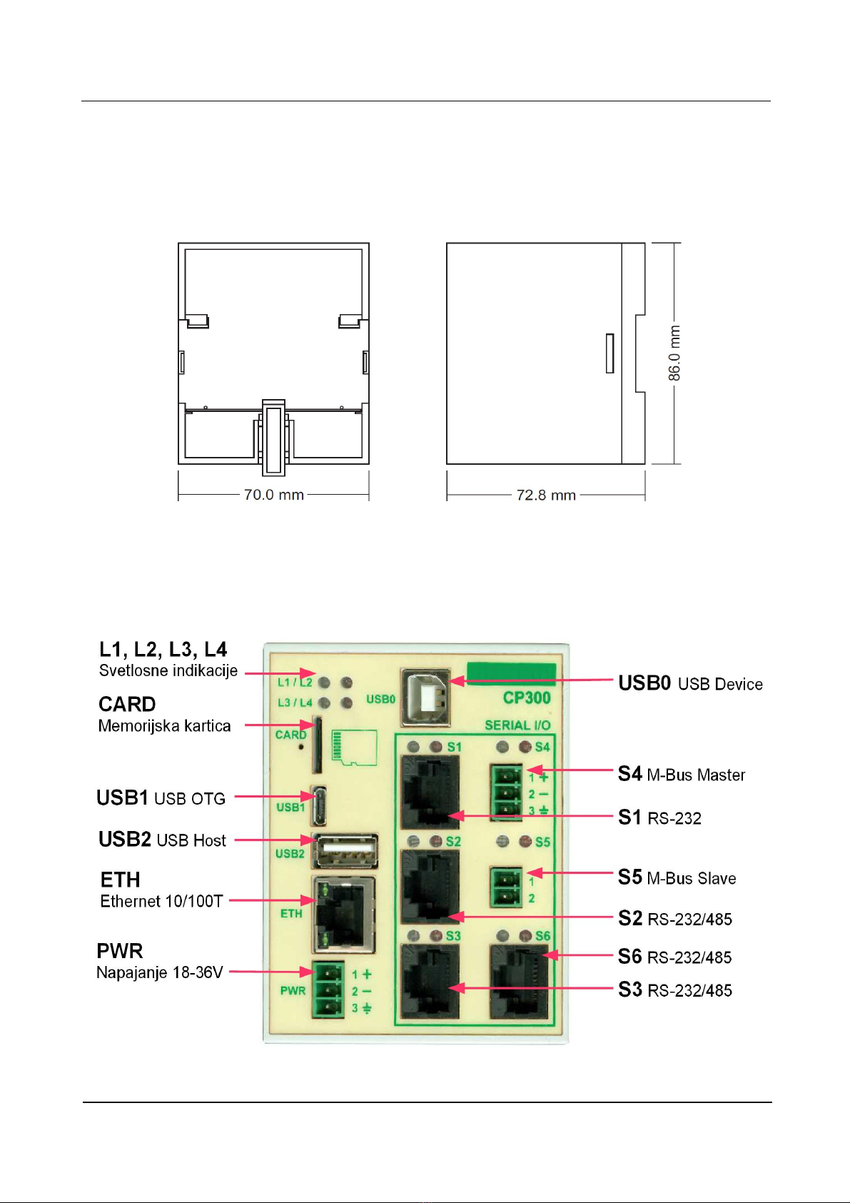
DL28 is contained in plastic enclosure with 70x86x72.8 di ensions and attach ent for
DIN 35 supporting rail.
Figure 2. Back and side view of DL28
Front plate is equipped with connectors for power supply, USB peripheral devices, e ory
cards, Ethernet and serial connected devices, as well as indicator lights. Following figure shows
DL28 front face with featured connectors explained.
Figure 3. DL28 front face connectors
14.05.2013. 2.
DL28 Installation and User Manual
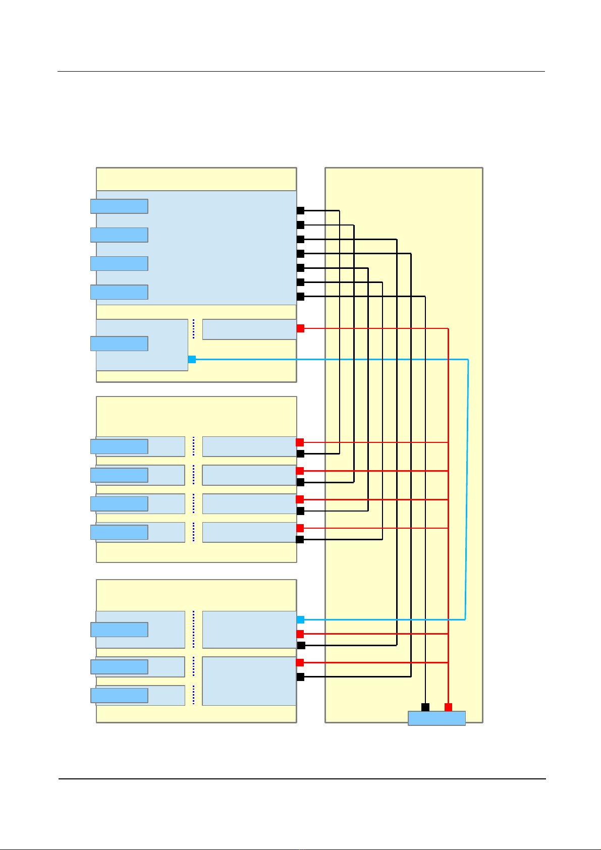
DL28 has odular design, consisting of four boards: processor board, co unication board,
M-Bus board and base board connecting all of the into single unit. All co unication ports are
galvanic isolated, the sa e applies to power supply connector.
Figure 4. DL28 block diagra
14.05.2013. 3.
PR CESS R B ARD
C MMUNICATI N B ARD
M-BUS B ARD
BASE B ARD
DUART
UART0
UART1
UART2
UART3
UART4
I2C
CARD
USB1
USB2
ETH
USB0
S1
S2
S3
I/O
DUART
UART0
UART3
UART4
S4
S5
S6
UART1
UART2
+3V, +5V
PWR

DL28 Installation and User Manual
2.1 Processor Board
The processor board is central part of DL28. It contains power section, processor odule and
headers for peripheral connectors, e ory cards and Ethernet connector.
Figure 5. DL28 Processor Board Block Diagram
14.05.2013. 4.

DL28 Installation and User Manual
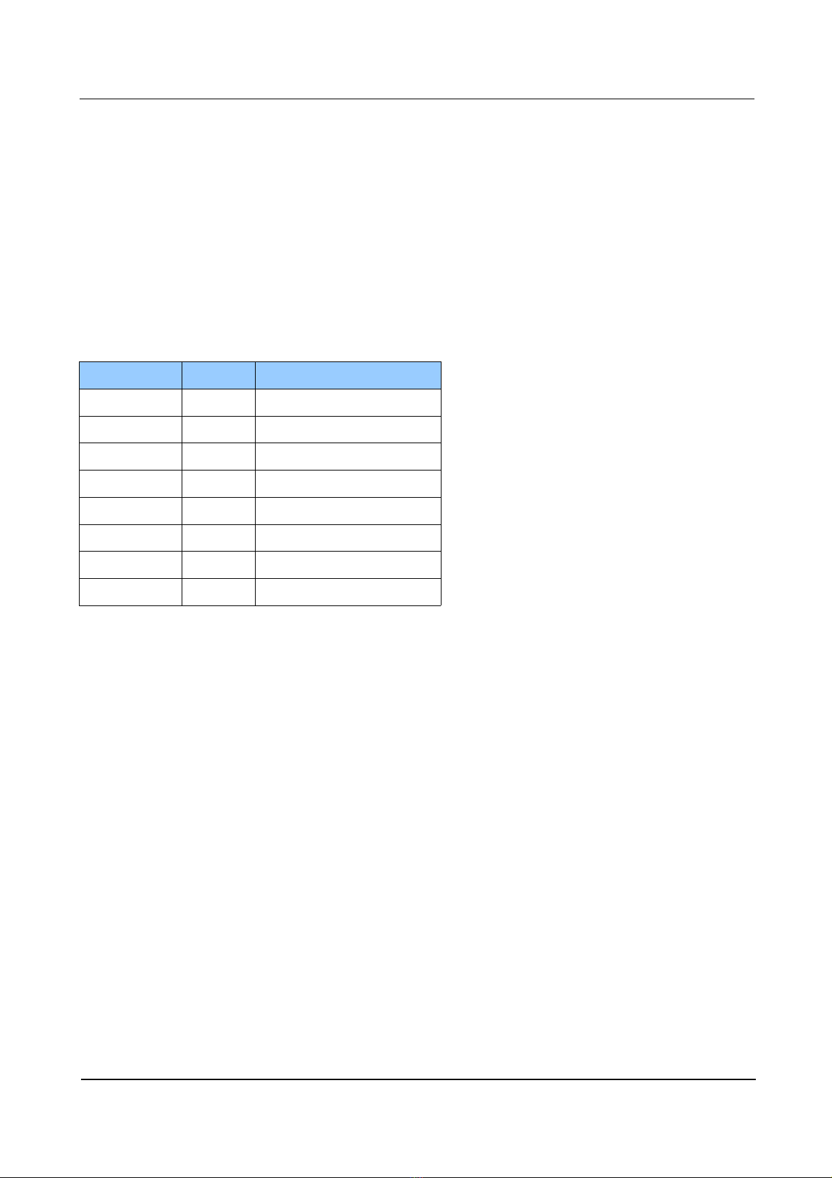
2.1.1 Indicator Lights
Indicator Lights use LEDs to show DL28 status and odes of operation.
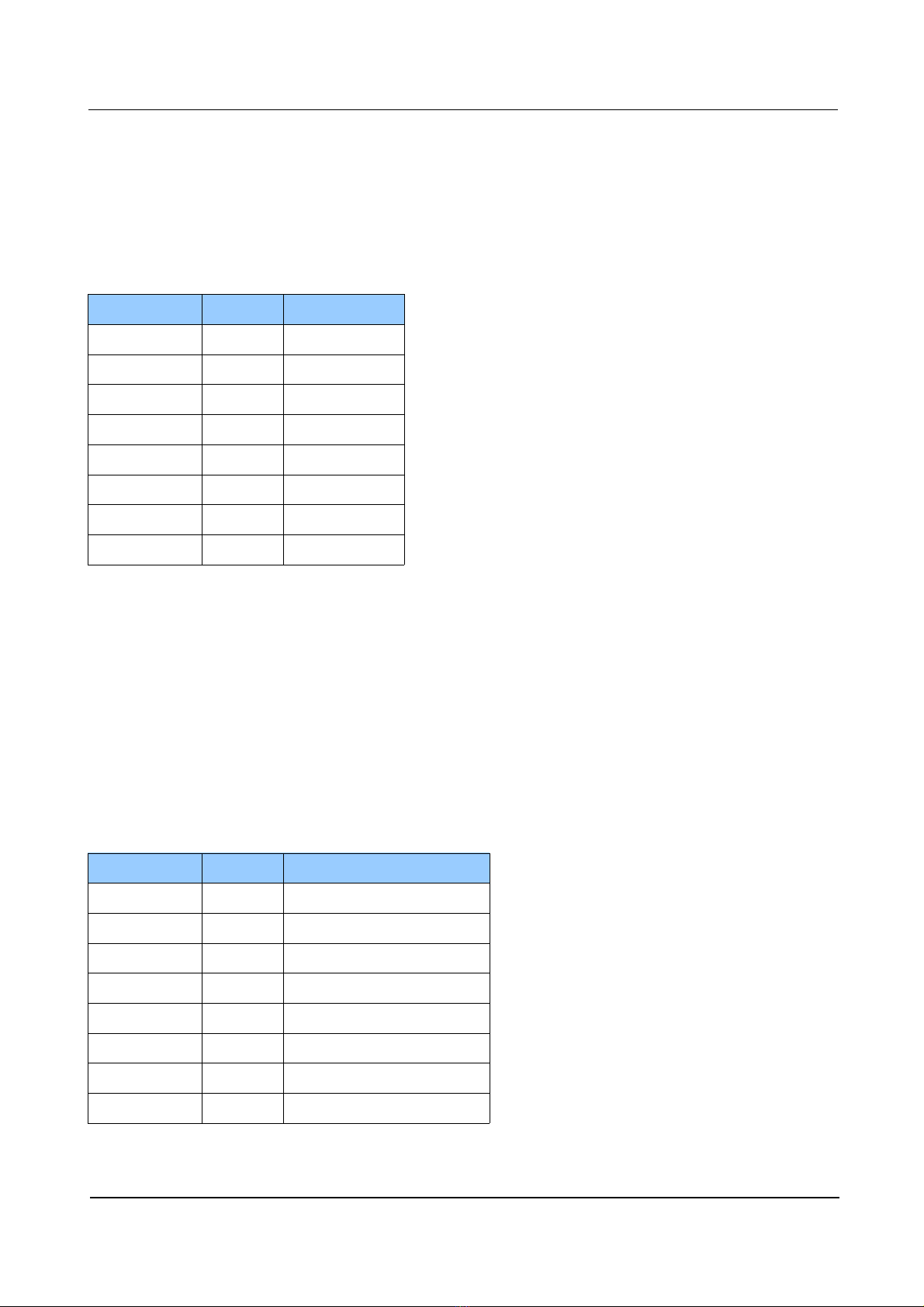
Marking Colour Purpose
L1 green power indicator
L2 red processor indicator
L3 green TBD
L4 red TBD
2.1.2 Memory Card
DL28 supports use of flash e ory cards belonging to icroSD for at. As the Figure 3.
shows, card should be introduced to slot with contact ele ents leading, while re aining on the left
side of the card.
2.1.3 USB Connectors
Three featured USB connectors are pre-deter ined as Host, Device and OTG connectors.
USB0 behaves as “Device”, type “B”, and is being used for Linux “co and line” interface. To
connect USB0 as device to PC host, VCP driver should be installed to PC after downloading fro
following web address: http://www.ftdichip.co /Drivers/VCP.ht USB1 behaves as OTG, type
“ icroAB”, while USB2 behaves as “Host” of type “A”. Both of the can be used for connecting
different USB peripherals such as e ory cards and si ilar.
2.1.4 Ethernet Connector
Ethernet Connector enables plugging into local co puter networks (LAN), wireless network
ode s (WLAN), cable ode s, GSM/GPRS routers ans si ilar co unication devices. It
supports 10/100TBase specification. RJ45 connector features indicators for device operation (upper
LED) and network activities (lower LED).
2.1.5 Power Connector
DL28 can be powered by DC sources ranging fro 18 to 30V. If used power source has 24V
the power consu ption is up to 5W. Indicator light L1 shows presence of power voltage.
Pin No. Signal Type
1 +V Positive voltage 18-36V
2 -V Negative voltage 18-36V
3 Ground ter inal
14.05.2013. 5.
DL28 Installation and User Manual
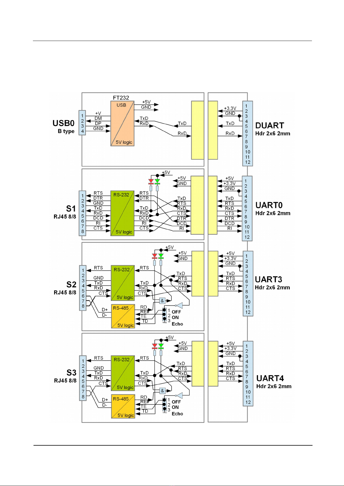
2.2 Communication Board
Co unication board features USB0 connection as well as three serial RS232/485
connections S1, S2, and S3. All of the are galvanic isolated.
Figure . DL28 Communication Board Block Diagram
14.05.2013. 6.
DL28 Installation and User Manual
2.2.1 Serial Connector S1
RJ45 8/8 port connects external devices to UART0 processor having seven RS-232C signals.
This port is used for connecting “dial-up”, GSM or other si ilar ode . Indicator lights located
above the RJ45 show status signals for sending TXD (red LED on the right) and receiving RXD
(green LED on the left).
Pin No. Signal Type
1 RTS Output
2 DTR Output
3 GND1 -
4 TXD Output
5 RXD Input
6 DCD Input
7 RI Input
8 CTS Input
2.2.2 Serial Connector S2
RJ45 8/8 port connects external devices to UART4 processor having four RS-232C and two
RS-485 signals. This port is used for connecting devices that use asynchronous serial
co unications, such as personal co puters (PC), progra able logic controllers (PLC) and
si ilar devices. Indicator lights located above the RJ45 show status signals for sending TXD (red
LED on the right) and receiving RXD (green LED on the left). Both signal types (RS-232C and RS-
485) can be active and operate si ultaneously. With “Echo” ju per on the co unication board,
two operating odes of RS-485 receiving can be set: OFF (1-2 position) for disabled sending echo
and ON (2-3 position) for enabled sending echo. Ju per “Ter ” enables 120Ω ter ination on RS-
485.
Pin No. Signal Type
1 RTS RS-232 Output
2 - not connected
3 GND2 -
4 TXD RS-232 Output
5 RXD RS-232 Input
6 A (+) RS-485 +
7 B (-) RS-485 -
8 CTS RS-232 Input
14.05.2013. 7.
DL28 Installation and User Manual
2.2.3 Serial Connector S3
RJ45 8/8 port connects external devices to UART3 processor having four RS-232C and two
RS-485 signals. This port is used for connecting devices that use asynchronous serial
co unications, such as personal co puters (PC), progra able logic controllers (PLC) and
si ilar devices. Indicator lights located above the RJ45 show status signals for sending TXD (red
LED on the right) and receiving RXD (green LED on the left). Both signal types (RS-232C and RS-
485) can be active and operate si ultaneously. With “Echo” ju per on the co unication board,
two operating odes of RS-485 receiving can be set: OFF (1-2 position) for disabled sending echo
and ON (2-3 position) for enabled sending echo. Ju per “Ter ” enables 120Ω ter ination on RS-
485.
Pin No. Signal Type
1 RTS RS-232 Output
2 - not connected
3 GND3 -
4 TXD RS-232 Output
5 RXD RS-232 Input
6 A (+) RS-485 +
7 B (-) RS-485 -
8 CTS RS-232 Input
14.05.2013. 8.
DL28 Installation and User Manual
2.3 M-Bus Board
M-Bus board serves as connection to syste s and devices through standard EN1434
connector, usually being used for eters and other easuring devices.
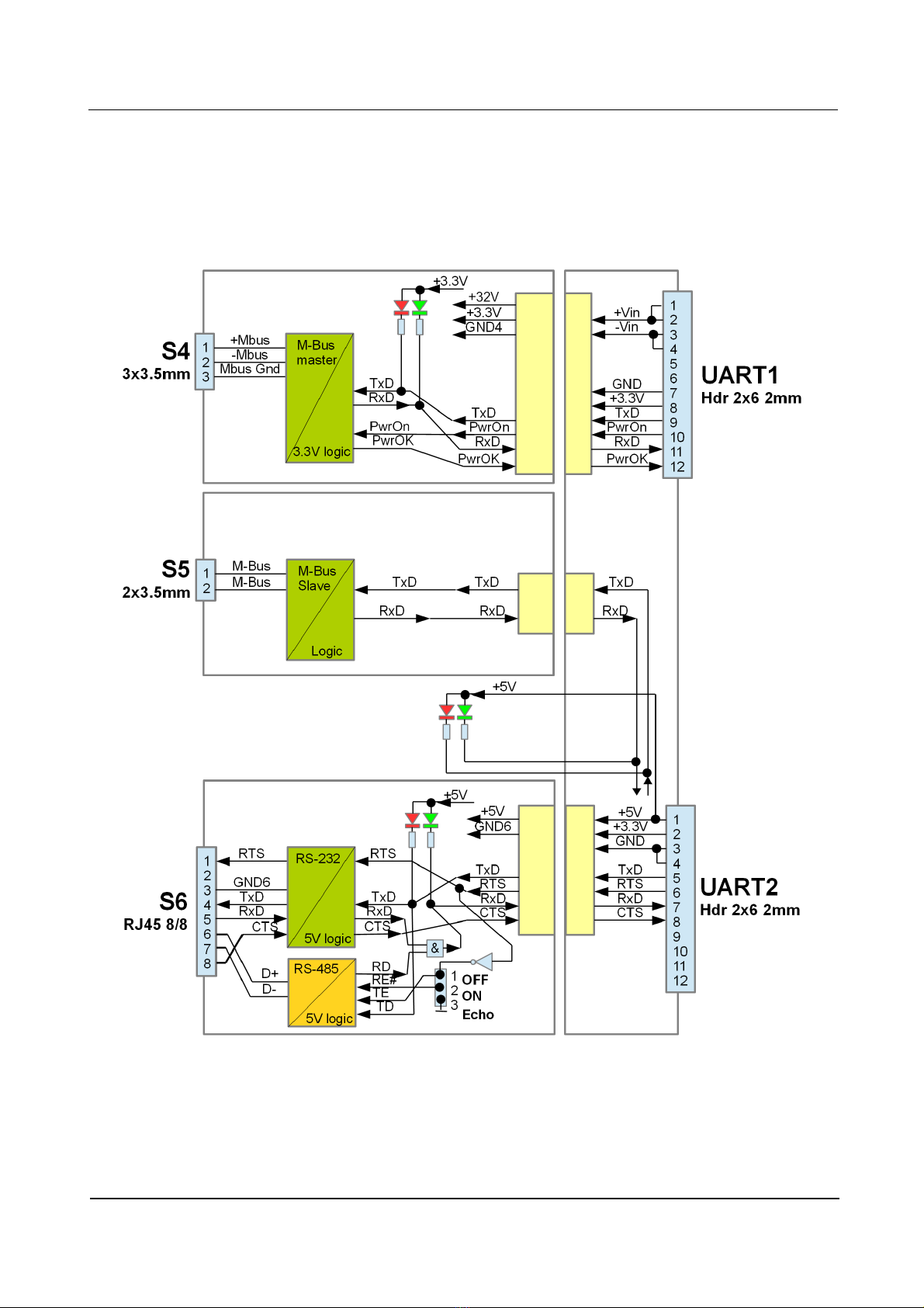
Figure 8. DL28 M-Bus Board Block Diagram
14.05.2013. 9.
DL28 Installation and User Manual
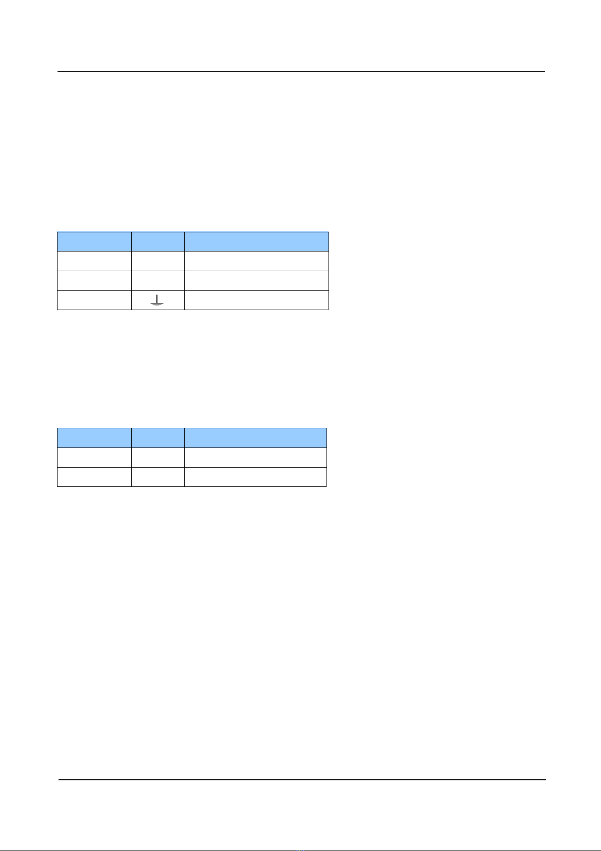
2.3.1 Serial Connector S4
3x3.5 connection blocks are used to link external devices to UART1 processor with M-
Bus aster interface according to EN1434. Up to 3 slave devices can be connected. S4 connector
accepts devices with M-Bus slave output such as heath eters, water eters or gas eters. Speeds
for this port connection should be in range fro 300b/s to 2400b/s while data for at is 8E1.
Indicator lights located above the connection blocks show status signals for sending TXD (red LED
on the right) and receiving RXD (green LED on the left).
Pin No. Signal Type
1 +MBus M-Bus aster + connector
2 -MBus M-Bus aster - connector
3 Grounding
2.3.2 Serial Connector S5
2x3.5 connection blocks are used to link external devices to UART2 processor with M-
Bus slave interface. Acceptable speeds for this port should be fro 300b/s to 2400b/s while data
for at should be set to 8E1. Indicator lights located above the connection blocks show status
signals for sending TXD (red LED on the right) and receiving RXD (green LED on the left).
Pin No. Signal Type
1 MBus M-Bus slave connector
2 MBus M-Bus slave connector
2.3.3 Serial Connector S6
RJ45 8/8 port connects external devices to UART2 processor having four RS-232C and two
RS-485 signals. Both types (RS-232C and RS-485) are active and operate si ultaneously. With
“Echo” ju per on the co unication board, two operating odes of RS-485 receiving can be set:
OFF (1-2 position) for disabled echo sending and ON (2-3 position) for enabled sending of echo.
Ju per “Ter ” enables ter ination on RS-485. S6 connector has parallel connection to S5
connector to enable UART2 sending/receiving through both ports.
Acceptable speeds for this port should be fro 300b/s to 2400b/s while data for at should be set to
8E1. Indicator lights located above the connection blocks show status signals for sending TXD (red
LED on the right) and receiving RXD (green LED on the left).
14.05.2013. 10.
DL28 Installation and User Manual
2.4 Base Board
Base board serves as echanical and electrical junction of above entioned boards.
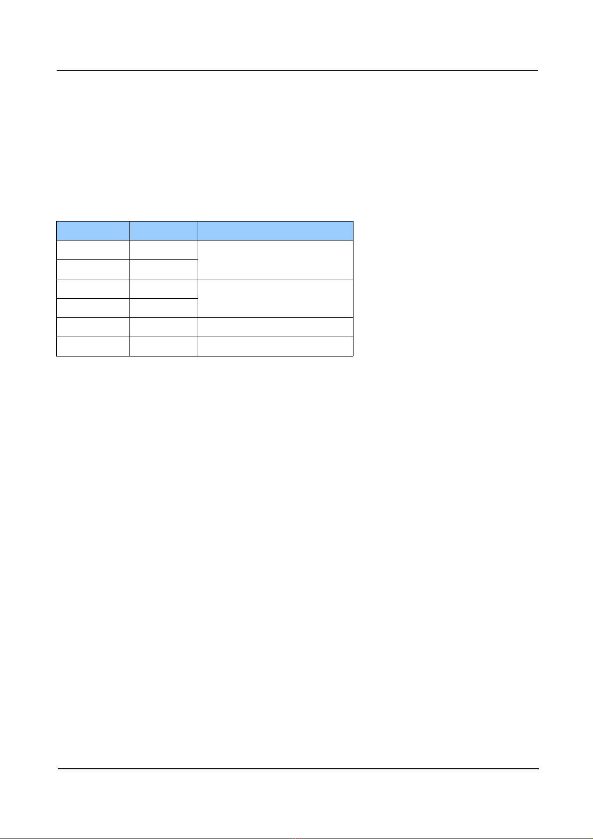
2.4.1 Expansion Port
DL28 features expansion port for adding other input/output co unication odules. In this
anner basic features can be enhanced and upgraded.
Pin No. Signal Type
1 GND Ground
2 GND
3 +5V expansion power supply
having 5V /100 A
4 +5V
5 SDA Data I/O
6 SCL Clock I/O
14.05.2013. 11.
DL28 Installation and User Manual
3 DL28 Connection Ports Testing
To execute tests, personal co puter should be used and connected by USB cable (A-B type).
“B” end of the cable should be plugged into USB0 port on the front of DL28. Since USB0 is
realised by integrated circuit FT232 (www.ftdichip.co ), virtual serial port driver should be
installed to PC after downloading fro the web address: http://www.ftdichip.co /Drivers/VCP.ht
On PC side the ter inal application (Windows Hyper Ter inal or Linux Ter inal) should be
started and set to listen newly installed virtual serial port (COM3 for instance) with co unication
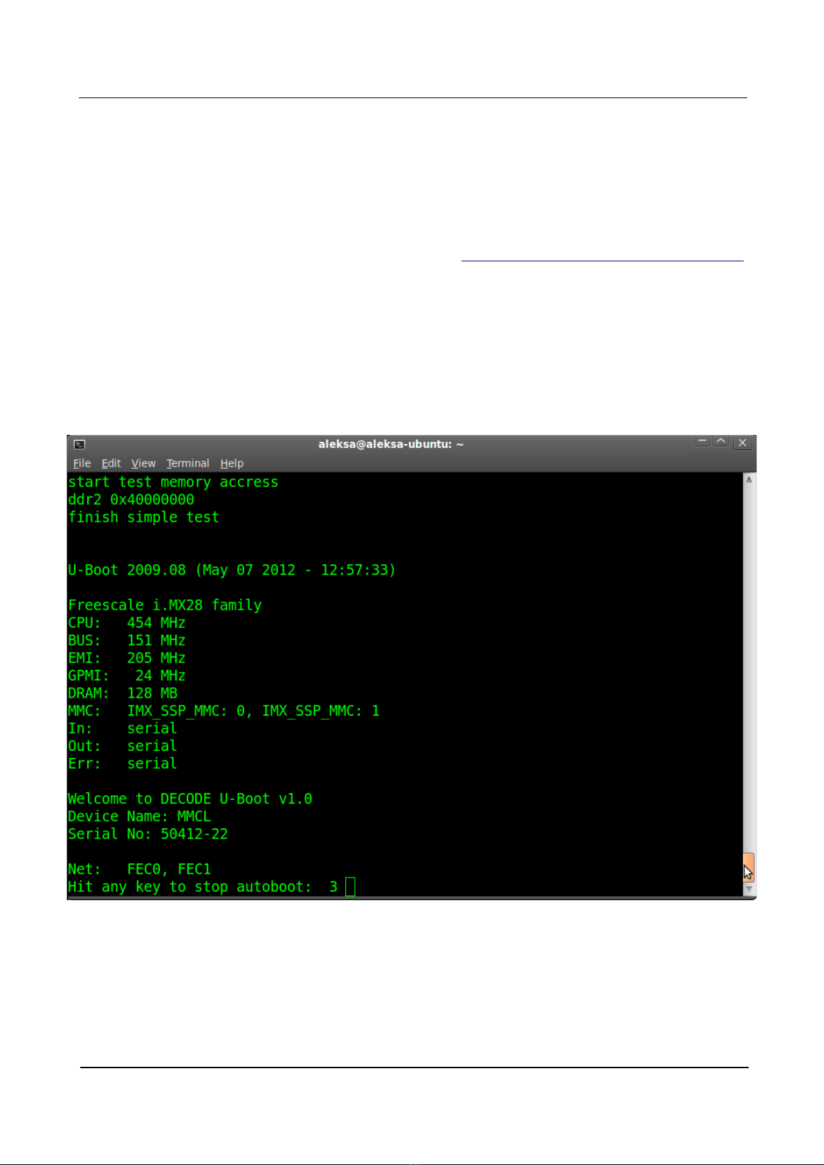
para eters 115200bps, 8N1. The next step is powering DL28. Ter inal application returns
following while DL28 is starting. Last text row shows info about possibility to cancel OS booting,
within 3 seconds, by hitting any key on the PC keyboard. After passing of 3 seconds, OS will
continue booting by default. Otherwise, if any key was activated, to start nor al OS booting, DL28
should be turned off and powered again.
Figure 9: Ter inal window appearance after starting device OS
USB0 can be regarded as successfully tested after the ter inal application on the PC has shown
DL28 boot listing.
14.05.2013. 12.
DL28 Installation and User Manual
3.1 User Login
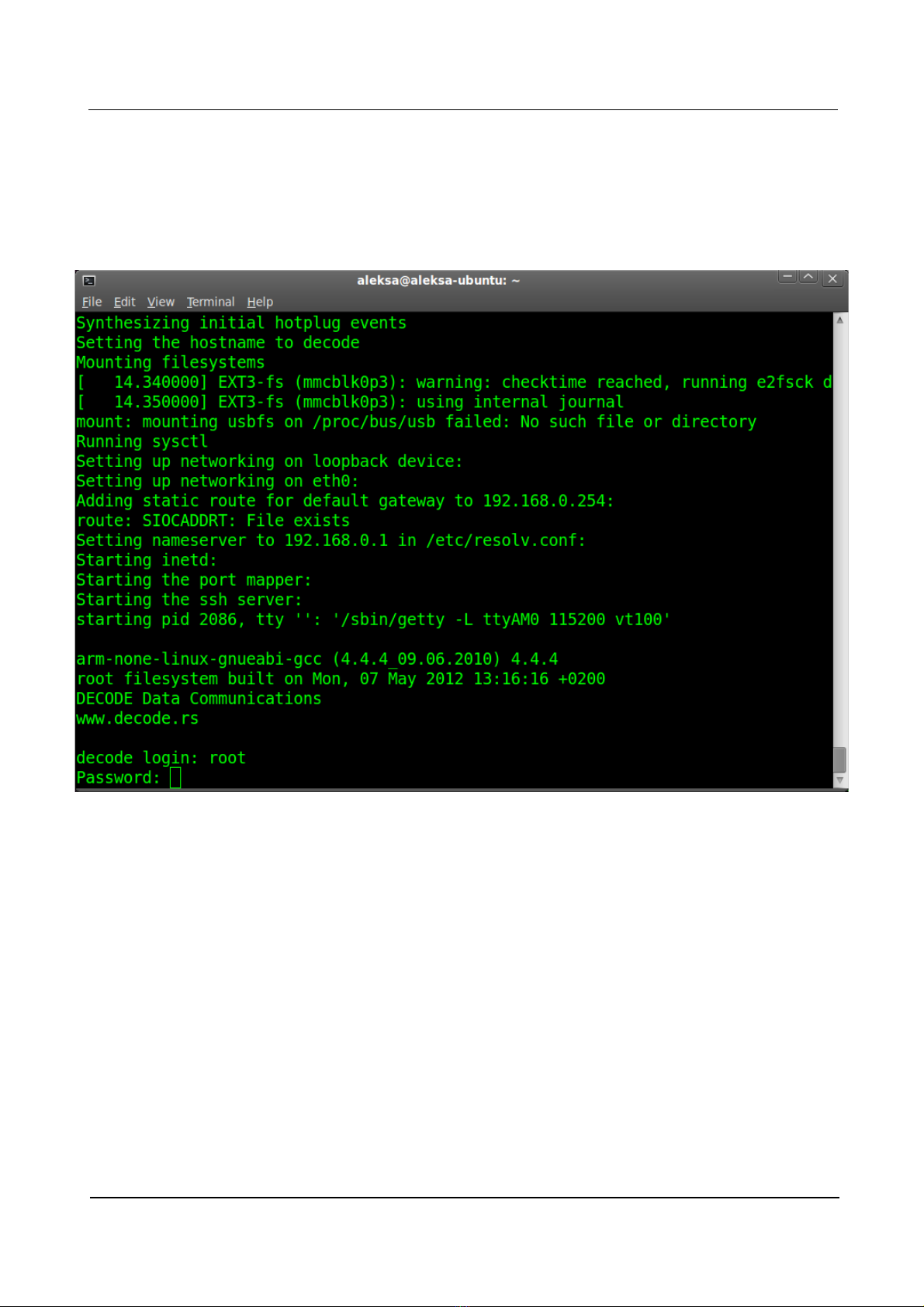
After several seconds fro starting device OS should be up and ready. Following screen shows
ter inal progra appearance after OS start, having the pro pt for user login at the botto .
Figure 10: Ter inal application screen with user login pro pt
Default access para eters are:
decode login: root
Password: root
14.05.2013. 13.
DL28 Installation and User Manual
3.2 Ports S1 ... S6 Testing
After successful login serial ports S1 ... S6 can be tested by starting following syste application:
root@decode~$./TestPort
After successful login serial ports S1 ... S6 can be tested by starting following syste application:
root@decode ~ ./TestPort
Test has 3 phases:
TEST1 – testing co unication between serial ports S1 and S2
TEST2 – testing co unication between serial ports S3 and S6
TEST3 – testing co unication between ports S4 (M-Bus aster) and S6 (M-Bus slave)
The outco e of tests can be observed fro the ter inal window.
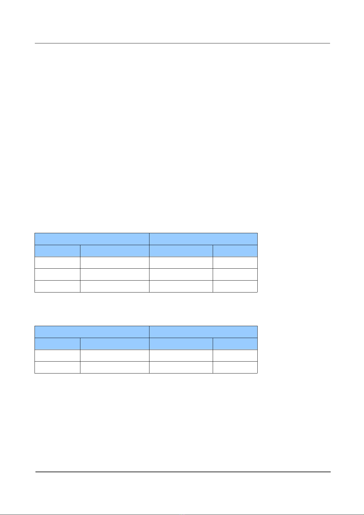
For serial ports testing cross-linked serial cable with RJ45 connectors should be ade as following:
RJ45 CONNECTOR 1 RJ45 CONNECTOR 2
Pin No. Signal Signal Pin No.
3 GND GND 3
4 TXD RXD 5
5 RXD TXD 4
For M-Bus ports testing two-wire cable with 2 poles and 3 poles connectors should be prepared as
following:
2 POLES CONNECTOR 3 POLES CONNECTOR
Pin No. Signal Signal Pin No.
1 MBus +MBus 1
2 MBus -MBus 2
14.05.2013. 14.

DL28 Installation and User Manual
3.2.1 TEST1
Following ter inal screen shows execution of TestPort syste application. After the TestPort is
started, user is asked to connect cross-linked RJ45 serial cable to ports S1 and S2, confir ing this
action with y and ENTER keys.
Figure 11: Terminal screen output after TEST1 execution
After co unication testing in both ways (S1--->S2 and S2--->S1) the TEST1 is co pleted and
application advances to TEST2 auto atically.
14.05.2013. 15.

DL28 Installation and User Manual
3.2.2 TEST2
For this test cross-linked RJ45 serial cable should be placed to ports S3 and S6 and confir ed
by entering y and ENTER keys.
Figure 12: Terminal screen output after TEST2 execution
After co unication testing in both ways (S3--->S6 and S6--->S3) the TEST2 is co pleted and
application advances to TEST3 auto atically.
14.05.2013. 16.

DL28 Installation and User Manual
3.2.3 TEST 3
All serial cables with RJ45 connectors should be re oved fro DL28 device for this test. Two-wire
conductors prepared earlier should be used between S4 and S5 ports.
During test co unication in S4--->S5 direction few unprintable characters will show in ter inal
window, which is nor al behaviour - it shouldn't be regarded as error state or ports failure
Figure 13. Terminal screen output after TEST3 execution
After co unication testing in S5--->S4 direction the TEST2 is successfully co pleted.
Particular test can be run separately by entering n and ENTER keys to all other, unnecessary tests.
Following screen shows successfully finished TEST2, while TEST1 and TEST3 were not run at all,
they finished unsuccessfully therefore.
14.05.2013. 17.
Table of contents


