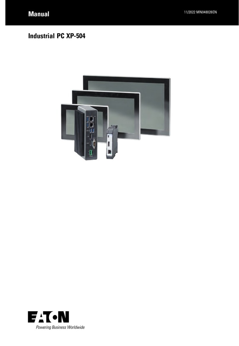
Christ touch-it xelo User manual

Touch-it XELO
Operating Instructions
Copyright / © Christ Electronic Systems GmbH 1/ 47 March 2017, Revision 17
a member of the Christ Company Group Document No.: E461201
Touch-it XELO
Touch Interface
Different Housings
Sizes From 7” to 23.8”
Ready For Use Touch Panel PC

Touch-it XELO
Operating Instructions
Copyright / © Christ Electronic Systems GmbH 2/ 47 March 2017, Revision 17
a member of the Christ Company Group Document No.: E461201
Document No.
E461201
Revision
March 2017, Revision 17
Address
Christ Electronic Systems GmbH
Alpenstraße 34
DE-87700 Memmingen
Telephone
+49 (0)8331 8371 –0
Fax
+49 (0)8331 8371 –99
E-Mail
Internet
http://www.christ-es.de
Copyright
No part of this documentation may in any form be reproduced, copied or
distributed by means of electronic systems without previous written per-
mission by Christ Electronic Systems GmbH. The translation into another
language also requires a written permission. This documentation may be
exclusively entrusted to the owner of the installation or to the employees
of Christ Electronic Systems GmbH.
Technical changes
Christ Electronic Systems GmbHreserves the right to change specifica-
tions, executions and technical data held within this document without
prior notice.
Trademarks
Brand and product names are trademarks or registered trademarks of
their respective owners.

Touch-it XELO
Operating Instructions
Copyright / © Christ Electronic Systems GmbH 3/ 47 March 2017, Revision 17
a member of the Christ Company Group Document No.: E461201
Table of contents
Page
1General ...................................................................................................................5
2Commissioning ......................................................................................................9
2.1 Mounting................................................................................................................................................................9
2.1.1 Touch-it XELO Open Frame / Open Frame glass........................................................................................................9
2.1.2 Touch-it XELO Front Panel / Front Panel glass......................................................................................................... 10
2.1.3 Touch-it XELO VESA / VESA glass.................................................................................................................................. 11
2.2 Interfaces Connector Side (CPU T56N)..................................................................................................... 12
2.3 Interfaces Connector Side (CPU GX-415GA / i5-4300U) ...................................................................13
2.4 Interfaces Connector Side (CPU i5-6300U).............................................................................................14
2.5 Extension Connector (additional Interfaces) ..........................................................................................15
3Software ...............................................................................................................16
3.1 American Megatrends, Inc. (AMI) BIOS................................................................................................... 16
3.1.1 Changing Display Resolution .......................................................................................................................................... 17
3.1.2 Changing Boot Priority....................................................................................................................................................... 18
3.1.3 Changing COM Port............................................................................................................................................................ 19
3.2 Redo Backup and Recovery..........................................................................................................................20
3.2.1 Generate bootable Redo Backup and Recovery USB stick .................................................................................. 20
3.2.2 Restoring an Image with Redo Backup and Recovery........................................................................................... 22
3.3 Generate an USB drive for BIOS update..................................................................................................24
3.3.1 List of needed files............................................................................................................................................................... 24
3.3.2 Format the USB Stick and make it bootable ............................................................................................................. 24
3.3.3 Copy the BIOS Update Files ............................................................................................................................................. 25
3.3.4 Configure the BIOS settings............................................................................................................................................. 25
3.3.5 Update the BIOS ................................................................................................................................................................... 26
3.4 Enhanced Write Filter EWF............................................................................................................................ 27
3.4.1 Enable or Disable the EWF Filter .................................................................................................................................... 27
3.5 SFTP Server.......................................................................................................................................................... 28
3.6 Hi-Safe (CPU N270 / T56N) .......................................................................................................................... 30
3.7 Observer (CPU GX-415GA / i5-4300U)..................................................................................................... 32
3.8 Observer (CPU i5-6300U) ..............................................................................................................................33
4Touch Calibration ................................................................................................34
4.1 Projected Capacitive Touch ..........................................................................................................................34
4.2 Foil-/Glass-Touch analog resistive 7” to 15” ..........................................................................................34

Touch-it XELO
Operating Instructions
Copyright / © Christ Electronic Systems GmbH 4/ 47 March 2017, Revision 17
a member of the Christ Company Group Document No.: E461201
5Interfaces .............................................................................................................36
5.1 Power Supply Connector ............................................................................................................................... 36
5.2 Grounding Bolt (if available)......................................................................................................................... 36
5.3 USB 2.0 Type A Connector ............................................................................................................................37
5.4 USB 3.0 Type A Connector ............................................................................................................................37
5.5 USB 3.1 Type C Connector ............................................................................................................................ 38
5.6 COM Connector ................................................................................................................................................ 38
5.7 COM Connector (CPU i5-6300U)................................................................................................................39
5.8 Ethernet Connector.......................................................................................................................................... 39
5.9 VGA Connector.................................................................................................................................................. 40
5.10 DVI-I Connector ................................................................................................................................................ 40
5.11 DisplayPort Connector.................................................................................................................................... 40
5.12 Line In / Line Out .............................................................................................................................................. 41
5.13 Extension Connector .......................................................................................................................................41
6Pointers ................................................................................................................42
6.1 Used symbols..................................................................................................................................................... 42
6.2 General pointers................................................................................................................................................ 42
6.3 Safety pointers................................................................................................................................................... 43
6.4 FCC Conformity (only Devices with FCC compliance).........................................................................45
6.5 Maintenance plan............................................................................................................................................. 46
6.6 Repairs ..................................................................................................................................................................46
6.7 Cleaning ...............................................................................................................................................................46

Touch-it XELO
Operating Instructions
Copyright / © Christ Electronic Systems GmbH 5/ 47 March 2017, Revision 17
a member of the Christ Company Group Document No.: E461201
1 General
OVERVIEW
Series
Touch-it XELO
Housing
Open Frame
Open Frame glass
Front Panel
Front Panel glass
Touch
Foil Touch, analog resistive
Projected Capacitive Touch
Sizes (Display)
7” –23.8”
CPU
AMD® G-T56N™Dual Core 1.65 GHz 64 Bit
AMD® GX-415GA™ Quad Core 1.5 GHz 64 Bit
Intel® Core™ i5-4300U Dual Core 1.9 GHz 64 Bit
Intel® Core™ i5-6300U

Touch-it XELO
Operating Instructions
Copyright / © Christ Electronic Systems GmbH 6/ 47 March 2017, Revision 17
a member of the Christ Company Group Document No.: E461201
Series
Touch-it XELO
Housing
VESA
VESA glass
Not available
Automation glass
Touch
Foil Touch, analog resistive
Projected Capacitive Touch
Sizes (Display)
7” –23.8”
CPU
AMD® G-T56N™Dual Core 1.65 GHz 64 Bit
AMD® GX-415GA™ Quad Core 1.5 GHz 64 Bit
Intel® Core™ i5-4300U Dual Core 1.9 GHz 64 Bit
Intel® Core™ i5-6300U
SYSTEM
CPU
AMD® G-T56N™ Dual Core 1.65 GHz
64-bit
AMD® GX-415GA
Quad Core™ 1.5 GHz 64 Bit,
2 MB Cache
Chipset
AMD A50M
Integrated in APU
Memory
4 GB DDR3
Radeon HD 8330E 500 MHz
Storage
32 GB Solid State Drive
250 GB Hard Disk Drive(optional)
32 GB MLC SSD / 128 GB MLC SSD / 500 GB
HDD
BIOS
AMI Plug & Play
AMI BIOS, Supports ACPI Function
Wake on LAN
Yes
H/W Status Monitoring
Supports power supply voltages and temperature monitoring
CMOS Battery
Lithium Battery
Operating System
Microsoft®Windows® Embedded
Standard 7 Enterprise / Premium
Linux (optional)
Windows® Embedded Standard 7 (WS7P)
Windows® Embedded Standard 7 (WS7E)
Windows® Embedded 8 Standard
Windows® 10 IoT
Linux

Touch-it XELO
Operating Instructions
Copyright / © Christ Electronic Systems GmbH 7/ 47 March 2017, Revision 17
a member of the Christ Company Group Document No.: E461201
CPU
Intel® Core™ i5-4300U
Dual Core 1.9 GHz 64 Bit,
3 MB Cache
Intel® Core™ i5-6300U
3 MB SmartCache
Chipset
Integrated in Intel® 4th Generation
Core™ i U-series
Integrated in 6th Generation
Intel® Core™U-Series Processor
Graphic
Intel® HD Graphics 4400 200 MHz
Intel® HD Graphics 520 300 MHz
Memory
4 / 8 / 16 GB DDR3L
Storage
32 / 64 / 128 / 256 / 512 GB MLC SSD
BIOS
AMI BIOS, Supports ACPI Function
Wake on LAN
Yes
H/W Status Monitoring
Supports Power Supply Voltages and Temperature Monitoring
CMOS Battery
Lithium Battery
Operating System
Windows® Embedded Standard 7 (WS7P)
Windows® Embedded Standard 7 (WS7E)
Windows® Embedded 8 Standard
Windows® 10 IoT
Linux
POWER SUPPLY
Supply Voltage
24 VDC ± 20%
Power Consumption
See specific datasheet
Power Switch
Only VESA and VESA glass housing

Touch-it XELO
Operating Instructions
Copyright / © Christ Electronic Systems GmbH 8/ 47 March 2017, Revision 17
a member of the Christ Company Group Document No.: E461201
MECHANICAL & ENVIRONMENTAL
Open Frame
Open Frame glass
Housing Front
Without Frame
Without Frame
Housing
Stainless steel or Aluminium
Stainless steel or Aluminium
Cooling
Active
Active
Protection Class
IP20
IP20
Operating Temperature
0 ~ 50 °C
0 ~ 50 °C
Front Panel
Front Panel glass
Housing Front
Aluminium frame / naturally anodized
Glass, black frame
Housing
Stainless steel or Aluminium
Stainless steel or Aluminium
Cooling
Active
Active
Protection Class
IP20 (IP 65 front)
IP20 (IP 65 front)
Operating Temperature
0 ~ 50 °C
0 ~ 50 °C
VESA
VESA glass
Housing Front
---
Glass, black frame
Housing
Aluminium / anodized silver, chemi-
cally shined or naturally anodized
Aluminium / anodized silver,
chemically shined or naturally
anodized
Cooling
Passive
Passive
Protection Class
IP20 (IP 65 front)
IP20 (IP 65 front)
Operating Temperature
0 ~ 45 °C (T56N)
0 ~ 50 °C
0 ~ 45 °C (T56N)
0 ~ 50 °C
Not available
Automation glass
Housing Front
Glass, black frame
Housing
Aluminium / anodized silver,
chemically shined or naturally
anodized
Cooling
Passive
Protection Class
IP65
Operating Temperature
0 ~ 50 °C
Dimensions
See specific datasheet
Weight
See specific datasheet
Storage Temperature
-10 ~ 70 °C
Humidity
5 ~ 80% (non condensing)
Certification
CE, EN55022, EN55024, DIN EN ISO 9001
CAUTION!
Never cover the Touch-it XELO completely or build it in a small closed
and unvented housing.

Touch-it XELO
Operating Instructions
Copyright / © Christ Electronic Systems GmbH 9/ 47 March 2017, Revision 17
a member of the Christ Company Group Document No.: E461201
2 Commissioning
2.1 Mounting
2.1.1 Touch-it XELO Open Frame / Open Frame glass
The variant Touch-it XELO Open Frame is designed for customer specific mounting.
Each Open Frame Panel has its own cut-out drawing.
For example:
For the appropriated drawing see the specific data sheet.

Touch-it XELO
Operating Instructions
Copyright / © Christ Electronic Systems GmbH 10 / 47 March 2017, Revision 17
a member of the Christ Company Group Document No.: E461201
2.1.2 Touch-it XELO Front Panel / Front Panel glass
The variant Touch-it XELO Front Panel is designed for front mounting.
Each Front Panel has its own cut-out drawing.
For the appropriated drawing see the specific data sheet.
To clamp the Front Panel into the cut-out you can use the attached fasting clamps (Vari-
ant Front Panel) or the mounted fasting clamps (Front Panel glass).
Front Panel
Front Panel glass
CAUTION!
For the best installation result the use of all provided fasting
clamps is highly recommended. Depending on individual installa-
tion circumstances a new IP rating may be considered.

Touch-it XELO
Operating Instructions
Copyright / © Christ Electronic Systems GmbH 11 / 47 March 2017, Revision 17
a member of the Christ Company Group Document No.: E461201
2.1.3 Touch-it XELO VESA / VESA glass
The variant Touch-it CE VESA is designed for VESA MIS-D, 75, C mounts.
Some panels can also be mounted with VESA MIS-D, 100, C.
Suitable mounting variants are:
VESA Desk Stand Arm Mounting System VESA-SA75

Touch-it XELO
Operating Instructions
Copyright / © Christ Electronic Systems GmbH 12 / 47 March 2017, Revision 17
a member of the Christ Company Group Document No.: E461201
2.2 Interfaces Connector Side (CPU T56N)
USB
2 x USB Host (Type A)
4 x USB Host (Type A) (optional)
Ethernet
2 x 1 GB Ethernet
Communication
1 x RS-232
Video
1 x VGA
Audio
Line In, Line Out (optional)
Power Connector
Phoenix
Connector side Touch-it XELO (CPU N270 / T56N)
Connector side Touch-it XELO extended (CPU N270 / T56N)
On/Off is only included with housing VESA and VESA glass.
All interfaces are described in the chapter Interfaces.

Touch-it XELO
Operating Instructions
Copyright / © Christ Electronic Systems GmbH 13 / 47 March 2017, Revision 17
a member of the Christ Company Group Document No.: E461201
2.3 Interfaces Connector Side (CPU GX-415GA / i5-4300U)
USB
2 x USB 3.0 Host (Type A)
2 x USB 2.0 Host (Type A) (optional)
Ethernet
2 x 1 GB Ethernet
Communication
1 x RS-232 or RS-422 or RS-485
(Can be set via BIOS)
Video
1 x DVI
WLAN
1 x 802.11 ac/a/b/g/n 2.4 GHz, 5 GHz, (optional)
Power Connector
Phoenix
Connector side Touch-it XELO (CPU GX-415GA / i5-4300U)
Connector side Optional (CPU GX-415GA / i5-4300U )
On/Off is only included with housing VESA and VESA glass.
All interfaces are described in the chapter Interfaces.

Touch-it XELO
Operating Instructions
Copyright / © Christ Electronic Systems GmbH 14 / 47 March 2017, Revision 17
a member of the Christ Company Group Document No.: E461201
2.4 Interfaces Connector Side (CPU i5-6300U)
USB
4 x USB Host 3.0 (Type A)
1 x USB Host 3.1 (Type C)
Ethernet
2 x 1 Gbit Ethernet (Intel I219LM + I211AT)
Communication
1 x RS-232 / RS422 / RS-485 (BIOS setting) (RJ50 10P10C)
Video
1 x DisplayPort
WLAN
1 x 802.11 ac/a/b/g/n 2.4 GHz, 5 GHz, (optional)
Power Connector
Phoenix
Connector side Touch-it XELO (CPU i5-6300U)
Connector side Optional (CPU i6-4300U )
On/Off is only included with housing VESA and VESA glass.
All interfaces are described in the chapter Interfaces.

Touch-it XELO
Operating Instructions
Copyright / © Christ Electronic Systems GmbH 15 / 47 March 2017, Revision 17
a member of the Christ Company Group Document No.: E461201
2.5 Extension Connector (additional Interfaces)
Extension Connector
1 x Emergency Stop
8 x Individual Selectable Buttons / Switches / LEDs
EtherCAT
1 x EtherCAT® Slave (Buttons / Switches / LEDs)
Additional connector side Touch-it XELO Automation

Touch-it XELO
Operating Instructions
Copyright / © Christ Electronic Systems GmbH 16 / 47 March 2017, Revision 17
a member of the Christ Company Group Document No.: E461201
3 Software
3.1 American Megatrends, Inc. (AMI) BIOS
AMI BIOS ROM has a built-in Setup program that allows users to modify the basic system con-
figuration. This type of information is stored in battery-backed CMOS RAM so that it retains the
Setup information when the power is turned off.
Entering Setup
Power on the computer and press “Del” or “F2” immediately. This will allow you to enter Setup.
Main
Set the date.
Advanced
Advanced BIOS Features Setup including COM setting, ACPI, etc.
Chipset
Host bridge parameters.
Boot
Boot option.
Security
Set setup administrator password.
Save&Exit
Exit system setup after saving the changes.

Touch-it XELO
Operating Instructions
Copyright / © Christ Electronic Systems GmbH 17 / 47 March 2017, Revision 17
a member of the Christ Company Group Document No.: E461201
3.1.1 Changing Display Resolution
3.1.1.1 CPU T56N
In the BIOS Setup mode choose the Chipset Menu select North Bridge and then
Graphics Configuration.
Set the LVDS2 Panel Type
Save this configuration by pressing “F4” and selecting “Yes” afterwards.
3.1.1.2 CPU GX-415GA
To change the display resolution the following settings must be done.
In the BIOS Setup mode choose the Chipset Menu select LVDS Panel Config Select.
Set the LVDS Panel Config Select.
Save this configuration by pressing “F4” and selecting “Yes” afterwards.
3.1.1.3 CPU i5-4300U
To change the display resolution the following settings must be done.
In the BIOS Setup mode choose the Chipset Menu select
System Agent (SA) Configuration -> Graphics Configuration -> LCD Control.
Set the LCD Panel Type.
Save this configuration by pressing “F4” and selecting “Yes” afterwards.
3.1.1.4 CPU i5-6300U
To change the display resolution the following settings must be done.
In the BIOS Setup mode choose the Advanced Menu select
LVDS(eDP/DP) Configuration.
Set the LCD Panel Type.
Save this configuration by pressing “F4” and selecting “Yes” afterwards.

Touch-it XELO
Operating Instructions
Copyright / © Christ Electronic Systems GmbH 18 / 47 March 2017, Revision 17
a member of the Christ Company Group Document No.: E461201
3.1.2 Changing Boot Priority
3.1.2.1 T45N
In order to boot from a USB Drive the following settings must be done.
In the BIOS Setup mode choose the Boot Menu and select Hard Drive BBS Priorities.
Set the Boot Option #1 in such a way that the USB Device is first position in the boot list, by
pressing “Enter” and select the USB Device using the Page-Up/Down Keys.
Save this configuration by pressing “F4” and selecting “Yes” afterwards.
3.1.2.2 CPU GX-415GA / i5-4300U
In order to boot from a USB Drive the following settings must be done.
In the BIOS Setup mode choose the Boot Menu and select Hard Drive BBS Priorities.
Set the Boot Option #1 to the USB Device, by pressing “Enter” and select the USB Device.
Save this configuration by pressing “F4” and selecting “Yes” afterwards.
3.1.2.3 CPU i5-6300U
In order to boot from a USB Drive the following settings must be done.
In the BIOS Setup mode choose the Boot Menu.
Set the Boot Option #1 to the USB Device, by pressing “Enter” and select the USB Device.
Save this configuration by pressing “F4” and selecting “Yes” afterwards.

Touch-it XELO
Operating Instructions
Copyright / © Christ Electronic Systems GmbH 19 / 47 March 2017, Revision 17
a member of the Christ Company Group Document No.: E461201
3.1.3 Changing COM Port
3.1.3.1 CPU GX-415GA
To change the COM Port to RS-422 / RS-485 / RS-232 the following settings must be done.
In the BIOS Setup mode choose the Advanced Menu select F81866 Super IO Configuration.
Select Serial Port0 Configuration and be sure that Serial Port [Enabled] is set.
Set the Mode Select to your favourite interface.
Save this configuration by pressing “F4” and selecting “Yes” afterwards.
3.1.3.2 CPU i5-4300U
To change the COM Port to RS-422 / RS-485 / RS-232 the following settings must be done.
In the BIOS Setup mode choose the Advanced Menu select NCT6102D Super IO Configura-
tion.
Select Serial Port0 Configuration and be sure that Serial Port [Enabled] is set.
Set the Mode Select to your favourite interface.
Save this configuration by pressing “F4” and selecting “Yes” afterwards.
3.1.3.3 CPU i5-6300U
To change the COM Port to RS-422 / RS-485 / RS-232 the following settings must be done.
In the BIOS Setup mode choose the Advanced Menu select Fintek Super IO Configuration
and then Serial Port1 Configuration.
Set the Device Mode to your favourite interface.
Save this configuration by pressing “F4” and selecting “Yes” afterwards.

Touch-it XELO
Operating Instructions
Copyright / © Christ Electronic Systems GmbH 20 / 47 March 2017, Revision 17
a member of the Christ Company Group Document No.: E461201
3.2Redo Backup and Recovery
3.2.1 Generate bootable Redo Backup and Recovery USB stick
There are two ways to create a Redo USB Drive with VMWare or directly booting a LiveCD.
VMWare:
Christ Electronic Systems GmbH created a complete VMWare Virtual Machine running
Redo V1.0.3
Download and Install VMWare Player 5.0 or higher
Download the VMWare Image (Redo 1.0.3.zip) from our SFTP in \out\Redo Images\ (See
chapter 3.5
Other manuals for touch-it xelo
1
Table of contents
Other Christ Industrial PC manuals


