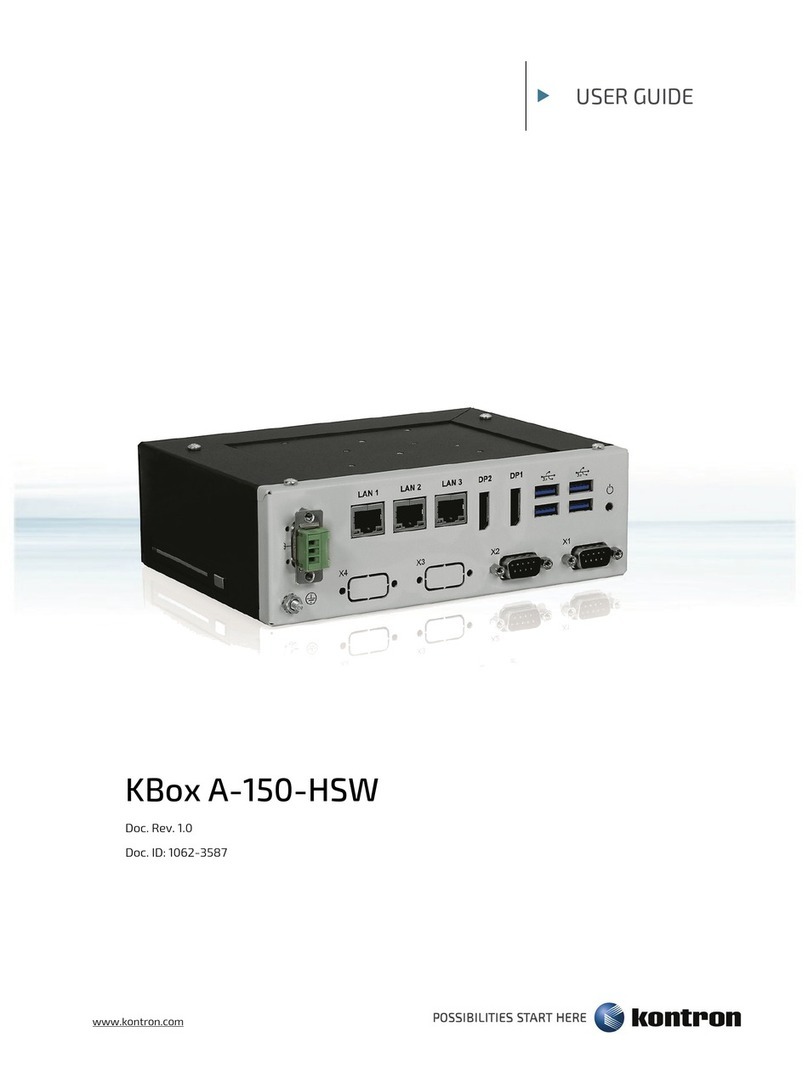
KBox A-150-KBL - User Guide Rev. 1.1
www.kontron.com // 10
5.2.1. M.2 Module ............................................................................................................................................................................................. 27
5.2.2. mPCIe Expansion Cards...................................................................................................................................................................... 27
6/ Accessing Components...................................................................................................................................................................28
Accessing the 2.5” HDD/SSD Drive Bay.............................................................................................................................................286.1.
Opening the System ...............................................................................................................................................................................296.2.
Installing and Removing M.2 SSD Card ............................................................................................................................................326.3.
Installing and Removing mPCIe Expansion Cards........................................................................................................................ 336.4.
7/ Thermal Considerations .................................................................................................................................................................34
Heatsink Plate............................................................................................................................................................................................347.1.
Heatsink (option) .....................................................................................................................................................................................347.2.
8/ Installation Instructions................................................................................................................................................................. 35
DIN Rail Mounting .................................................................................................................................................................................... 358.1.
Control Cabinet Mounting ....................................................................................................................................................................368.2.
Wiring the DC Mating Power Connector .......................................................................................................................................... 378.3.
9/ Switching On.......................................................................................................................................................................................39
Switching On for the First Time........................................................................................................................................................... 399.1.
Switching Off.............................................................................................................................................................................................409.2.
Switching On .............................................................................................................................................................................................409.3.
Operating System (OS) and Drivers ..................................................................................................................................................409.4.
10/ Technical Data ....................................................................................................................................................................................41
Block Diagram...........................................................................................................................................................................................4110.1.
Technical Specification........................................................................................................................................................................4210.2.
Mechanical Specification ....................................................................................................................................................................4310.3.
10.3.1. Mechanical Diagrams........................................................................................................................................................................43
Environmental Specification .............................................................................................................................................................4710.4.
Standards, Certifications and Directives ....................................................................................................................................... 4710.5.
Power Specification..............................................................................................................................................................................5010.6.
10.6.1. Power Protection Requirements ...................................................................................................................................................50
10.6.2. Power Consumption...........................................................................................................................................................................51
10.6.3. Protective Earth Stud Bolt................................................................................................................................................................51
11/ Connector Pin Assignments..........................................................................................................................................................52
Front Panel Connector Pin Assignments......................................................................................................................................... 5211.1.
11.1.1. DC Input Power Connector (-+)...................................................................................................................................................... 52
11.1.2. HDMI Connector (HDMI) .................................................................................................................................................................... 52
11.1.3. Display Port Connector (DP) ............................................................................................................................................................ 52
11.1.4. GbE LAN RJ45 Connectors (LAN1, LAN2) ...................................................................................................................................... 53
11.1.5. USB 3.0 Port Connectors ................................................................................................................................................................... 53
11.1.6. Serial Port Connectors (X1, X2)........................................................................................................................................................ 53
SBC On-board Connector and Jumper Pin Assignments ...........................................................................................................5411.2.
11.2.1. Battery Power Input Connector ......................................................................................................................................................54
11.2.2. 12 VDC Out Power Connector ..........................................................................................................................................................54
11.2.3. HDD Power Output Connector ........................................................................................................................................................54
11.2.4. SATA1 and SATA2 Port Connector .................................................................................................................................................54
11.2.5. Serial Port 1 and Serial Port 2 Connector .................................................................................................................................... 55
11.2.6. USB 2.0 Port Pin Header.................................................................................................................................................................... 55
11.2.7. Audio Input/Output Pin Header...................................................................................................................................................... 55
11.2.8. Left Channel 3W Audio AMP Output Connector ....................................................................................................................... 56
11.2.9. Right Channel 3W Audio AMP Output Connector ..................................................................................................................... 56
11.2.10. Power-on Switch Pin Header ........................................................................................................................................................ 56
