VALUELINE IPC
2643_en_K PHOENIX CONTACT 3
Temperature data (operating)1
No display
12-in. display
15-in. display
17-in. display
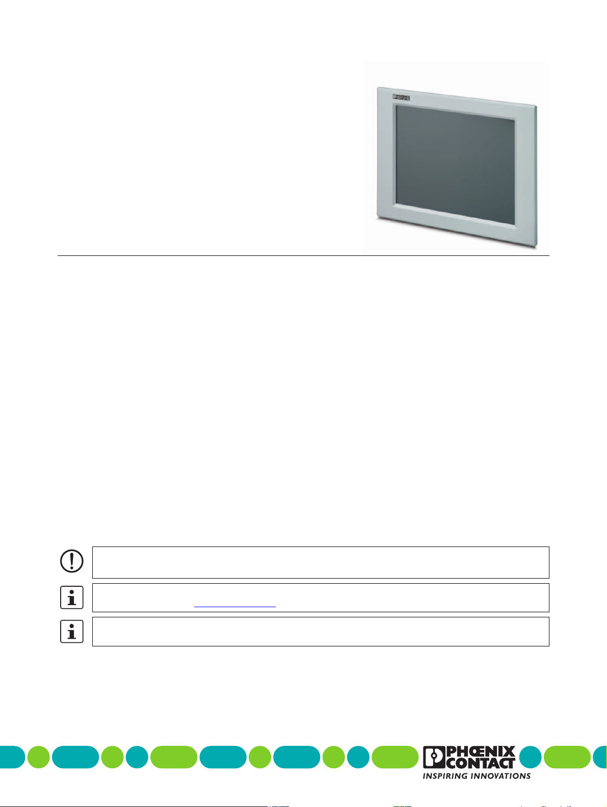
19-in. display
18.5-in.display
21.5-in.display
24-in. display
Celeron®M and Core™2 Duo with CompactFlash®card or solid-state drive -20 …40°C -20 … 45°C 0 … 45°C
Celeron M and Core 2 Duo with rotating hard-disk drive 0 … 40°C 0 … 45°C 0 … 45°C
Atom™with CompactFlash card or solid-state drive -20 … 55°C -20 … 50°C 0 … 50°C
Atom with rotating hard-disk drive 0 … 55°C 0 … 50°C 0 … 50°C
1Temperature values at 100% CPU utilization
Electrical data
Power supply, nominal 24 V DC
Power supply, range 19.2 … 28.8 V DC
Connection Removable Combicon screw-type
Conductor size 0.2 … 2.5 mm² (24 … 12 AWG)
Torque 5 … 6 Nm
RTC battery, typical life 5 years
Recommended power supply size
Atom™ processor with no display, 12-inch, 15-inch display 2.5 A
All other processors 5.0 A
Any configuration with PCI slots 5.0 A
Computer data
Operating system (configurable option) Windows®XP
Windows 7
Windows Embedded Standard 7
Processor (configurable option) 1.60 GHz Intel®Atom™ N270, 533FSB, 512 kB L2 Cache
1.06 GHz Intel Celeron®M, 533FSB, 1 MB L2 Cache
1.5 GHz Intel Core™2 Duo, 667 FSB, 4 MB L2 Cache
RAM (configurable option) 1 GB … 3 GB
Data memory (configurable option) 2.5 in. SATA hard-disk drive
2.5 in. SATA solid-state drive
CompactFlash®
Optical drive (configurable option) CD-RW/DVD-RW
Number of CompactFlash®slots (configurable option) 2 maximum
Number of PCI slots (configurable option) 2 maximum
PCI card size (maximum)
Slot 1
Slot 0
169.8 x 106.3 mm
180.9 x 107.9 mm
Maximum current draw per PCI slot 600 mA
Interfaces
USB 4x Type A, USB 1.1/2.0
Serial, RS-232 (configurable option) DB-9, male
Video VGA (DB-15, female)
DVI-D1
NVRAM connection Mini-PCI (on-board)
NVRAM size (configurable option) 128 kB
Number of Ethernet connectors 2
Ethernet connection 10/100/1000 Mbps
1DVI-D port not included with Atom processor