Dectron DRY-O-TRON DA2 007 Specification sheet

Dectron, Inc. November 2009 1
Data subject to change without notice.
Owners Manual
FOR MODELS
DA2 DV2
007 007
016 016
024 024
035
045
054
070
For future reference, write your model number here ______________
write your serial number here ______________
write your ref number here ______________

DA2 Series Dehumidifier Owners Manual
2Dectron, Inc. November 2009
Data subject to change without notice.
USER AGREEMENT:
Where any differences exist between the named electronic file obtained directly from Dectron,
Inc. and other versions, the named electronic file shall have precedence. Electronic versions
are subject to validation by Dectron, Inc.
CANADA
DECTRON INC.
4300 Poirier Boulevard
Montreal, QC.
H4R 2C5
Tel.: 514-334-9609 or
1-800-667-6338 or
1-888-DECTRON
U.S.A
DECTRON INC.
10898 Crabapple Road
Suite 103
Roswell, GA 30075
Tel.: 770-649-0102 or
1-800-676-2566
Fax: 770-649-0243
Corresponding Electronic File Name:
DA2_2009-Nov-30.pdf
NOTE:
For your convenience this manual is organized into tasks arranged in a workable order. Most
material relevant to a single task is on one page or a group of sequential pages.
Please attach copies of the appropriate pages to the task contract or work-order. License is
hereby granted to copy and distribute as appropriate any pages contained herein for the sole
purpose of assisting in the proper application, installation, operation, maintenance, and/or
service of one Dectron unit only. All other rights are retained by Dectron.
To the Owner:
This manual contains important instructions on designing for, installing, starting, operating, and
maintaining your DRY-O-TRON® and system. Please read the entire manual carefully and if you
have any questions contact your local Dectron representative.
Your warranty is valid only if conditions explained in this manual are met.
To the Installer:
This manual contains vital instructions for installing and starting up the DRY-O-TRON® and
system. Please read the entire manual carefully and if you have any questions contact your local
Dectron representative. Your customer’s satisfaction is at stake and the DRY-O-TRON® warranty
may be void if conditions explained in this manual are not met.
Heating, Cooling, or Dehumidifying Construction Sites
The DRY-O-TRON®unit is not a convenience air conditioner. Its capacity is carefully
matched to the expected load. Errors of installation, damage to the unit, and other
performance reductions will be obvious once the building begins normal use.
Never use the unit to heat, cool, or dehumidify a construction site. The air coils must be
protected against construction dusts until all construction dusts have been removed from the
space. Construction dusts bind to the cooling coil permanently and cannot be removed. Once
bound, the dusts reduce heat transfer and airflow rate. Filters will not prevent this.
The resulting performance reduction and possible component damage are not covered by
the Dectron warranty.

Dectron, Inc. November 2009 3
Contents
Data subject to change without notice.
DRY-O-TRON® is the original energy recycling dehumidifier.
Tens of thousands of units have been installed throughout
the world, and DRY-O-TRON® has become synonymous
with quality, reliability and energy savings.
Dectron Inc., the inventor of DRY-O-TRON®, is a company
committed to being the absolute best at what they do -- pro-
viding leading expertise and quality products to customers
who need to control high humidity efficiently.
Today’s DRY-O-TRON® represents years of intensive
research and development by a team of highly qualified
experts. Dectron has the only large-scale dehumidifier test-
ing
and environmental simulation laboratory
in the industry.
Every DRY-O-TRON® model line has been developed in this
laboratory, and every customer’s unit is fully factory tested
before shipment.
The DRY-O-TRON® is available in a broad range of standard
products for industrial and commercial applications. We also
have a team of highly skilled engineering and manufacturing
professionals who are dedicated to custom design projects.
DRY-O-TRON® DA2/DV2
Series Dehumidifiers for
Industrial and Commercial
Applications
Page
Product Description 4
Nameplate 5
Safety Information 6
Unloading and Lifting 8
Installation
Unpacking & Locating 9
Mounting 10
Airflows 11
Ducts 12
Piping 14
Wiring 16
Unit-Duct Connections 21
Startup
Pre-Startup Adjustments 18
Pre-Startup Checklist 19
Blower Speed 23
Oil Level 24
Notices 25
Enable Operation & Adjust TXV 26
Startup Report 29
Operation
Maintenance 30
Diagnostics 33
Warranty 39
Owners Manual DA2 Series Dehumidifier
The DA2 Series
ΔΔReduces building repair costs
ΔΔReduces ice surface maintenance
ΔΔ
Helps eliminate fog and condensation
ΔΔContributes to space heating
The DA2 Series Features
ΔΔVery simple and energy efficient
operation - simply turn on the unit
during active use periods.
ΔΔLow maintenance operation
ΔΔAutomatic rapid defrost
Humidity in Ice Rinks
There are two sources of moisture in
an indoor ice rink: infiltration and
spectators. This moisture travels
from warm areas to cold areas, since
the colder surface has a lower vapor
pressure. In an ice rink, this move-
ment is predominantly toward the ice.
Some moisture will also move toward
the ceiling.
If the cold surface temperature is
below the dewpoint of the air, con-
densation will occur.
The visible effects of condensation
are fog near the ice surface, and
water droplets on the ceiling. In
extreme case, inverted icicles may
form on the ice surface.
Fog Near the Ice Surface
Fog is formed when moisture laden
air at the ice surface cools to or below
its dew-point temperature.
The ice surface actually acts as a
dehumidifier, freezing moisture from
the air onto the surface as additional
ice. This process increases the load
on the ice-making equipment and
wastes energy.
The ice surface, the boards, and the
spectator guards trap a pool of
moisture-laden air on top of the ice.
To remove the moisture without
melting the ice, units must be
properly installed in pairs. (See
Installation.)

DECTRON
DA2 Series Dehumidifier Owners Manual
Product Description
DESCRIPTION
4Dectron, Inc. November 2009
Data subject to change without notice.
Room Air Supply Air
Room air is drawn into the unit by the blower. Part of the air enters a cooling coil, where its temperature is
decreased below its dew point. Water will condense from the air onto the cooling coil. In some cases, this water
may drip into a collection pan and exit the unit through a pipe (by others). In other cases, the condensed water
may collect on the cooling coil as frost.
The remainder of the air enters a condenser, where the refrigerant gives up its heat to the air.
The resulting streams of warm and cold air are mixed together and the resulting supply air is delivered to the
space as described elsewhere.
If frost builds up on the cooling coil, it will provoke a periodic defrost mode. During this mode, hot refrigerant
enters the cooling coil, causing the frost to melt. The resulting water droplets fall into the collection pan, and flow
out through the condensate pipe (by others).
Return Air
SAMPLE ONLY
Layout may vary.
Return Air
SAMPLES ONLY
Layout may vary.
A minimum length of
supply duct is
required.

DESCRIPTION
Owners Manual DA2 Series Dehumidifier
Dectron, Inc. November 2009 5
Data subject to change without notice.
Product Description
DRY-O-TRON ®
MODEL #: DA2-024-8
SERIAL #:
I.D. T
ELECTRICAL RATING
575 V ac, 3 ph, 60 Hz
COMPRESSOR 50.0 LRA 7.9 RLA
BLOWER MOTOR 2HP 2.4 FLA
MCA 13 A MAX. FUSE/CKT. BKR. 20 A
REFRIGERAN T TYPE
R-22
FACTORY CH ARGE 15.5 lbs
AIR VO LU ME 3600 - 4000 CFM
BELT SIZE
WIRINGDIAGRAM DA2-W-024-021 AE Rev.5
REFRIGERANT DESIGN PRESSURES: HIGH/LOW 3 00/150 PSIG
COMFORMS TO UL STD 1995
CERTIFIED TO STDCAN/CSA-
C22.2NO.236
FABRIQUÉAU CANADA / MADEIN CANADA
REF.: DC23154
POOL # 1: ft² POOL # 3: ft²
E.W.T.: °F E.W.T.: °F
POOL # 2: ft² POOL # 4: ft²
E.W.T.: °F E.W.T.: °F
AIR TEMP .: 60 °F R.H.: 60 %
R-22
TOTAL SYSTEM CHARGE:
15.5 lbs
OIL TO BE ADD ED AT STAR T-UP oz
OIL TYPE
MAX.LENGTH OFREF. LINES (ONE WAY) ft
BETWEEN D.O.T.& REMOTE CONDENSER:
LINE SIZE:
AIR COOLED COND.MODEL #: HOT GAS: in
LIQUID: in
2001406
CSA and ETL Label
Operating conditions: Make sure unit is operating within these
conditions. Unit has been selected and sized accordingly.
Name plate
on corner
Nameplate specifications supersede any other specifications
or statements found in this manual.
If assistance is needed, have
model, serial number, and Ref.
number (below) before calling.
Important branch circuit information
Replace with
belt of same
type and size
when necessary.
Ref number
Indoor unit
Model Nomenclature:
ixx-sss-vvp
D = indoor cabinet
nominal moisture
removal capacity in
lbs./hr.
A2 = low to medium temperature dehumidifier
nominal voltage
2 = 208V, 1Φ, 60 Hz
3 = 230V, 1Φ, 60 Hz
4 = 208-230V, 1Φ, 60 Hz
5 = 208-230V, 3Φ, 60 Hz
6 = 230V, 3Φ, 60 Hz
7 = 460V, 3Φ, 60 Hz
8 = 575V, 3Φ, 60 Hz
9 = 208V, 3Φ, 60 Hz

DA2 Series Dehumidifier Owners Manual
Warnings, Cautions, Notices
6Dectron, Inc. November 2009
Data subject to change without notice.
NOTICE The information presented in this section represents Dectron’s best effort as of the time of issue. This
information should be considered in receiving, unloading, transporting, installing, and operating the
equipment.
Dectron does not warrant that this information is complete for any particular application. Where job-
specific modifications were required, those changes whill be documented in addenda shipped separately.
Where any steps are not clear, Dectron offers technical assistance at 1-800-667-6338 or
1-800-676-2566.
Follow all applicable safety rules and regulations. Where any recommendations in this manual conflict
with safety or any other legal requirements, those requirements take precedence.
Dectron, Inc. does not engage in transportation services or material-handling services, installation serv-
ices, air-balancing services, or operation services. All costs, risks, and responsibilities of safety,
transportation, handling, moving, damage prevention, proper installation, and proper operation are borne
by others.
Dectron, Inc. does not engage in Startup contracting. All costs, risks, and responsibilities of properly
starting the equipment are borne by others. Dectron does offer on-site factory personnel to supervise
the startup process. There is a fee for this service.
WARNING Risk of electric shock. Can cause injury or death.
Some procedures could expose personnel to the risk of electric shock. Electric
shock can cause injury or death.
The unit controller does not disconnect electrical energy from the unit, even in the
OFF condition. Use only approved devices (e.g. locking safety switch), to disconnect,
lockout, and tagout all sources of electrical energy before working inside the unit
cabinet. Follow all applicable safety regulations.
Risk of stray voltage.
Ground the unit using the grounding lug provided.
Risk of overheating electrical connections.
Use only copper wire to connect the unit. The power input lugs are not sized for use
with other wire. For units with factory-supplied disconnects, follow instructions inside
the disconnect.
Risk of explosive pressure release. Can cause injury or death.
This product contains refrigerant liquid and vapor under high pressure. Some
installation and service procedures could expose personnel to the risk of explosive
discharge. Some installation and service procedures could expose personnel to the
risk of frostbite from release of refrigerant.
Reclaim refrigerant to reduce the pressure to atmospheric before working on pipes,
valves, heat exchangers, compressors, pressure switches, etc.
Once opened, do not close any manual refrigerant valves that might isolate
refrigerant from the relief valve. If necessary, install relief valves (by others).
WARNING
Risk of contact with moving parts. Can cause injury or death.
This product contains rotating parts and V-belt drives. Some installation, service, and
maintenance procedures could expose personnel to the risk of injury or death from
contact with these parts.
Using only approved devices (e.g. locking safety switch), disconnect, lockout, and
tagout all sources of electrical energy before working inside the unit cabinet. Allow
adequate time for rotating parts to stop. Follow all applicable safety regulations.
Do not operate the unit until ductwork or a screen is installed at each blower outlet.
WARNING

Owners Manual DA2 Series Dehumidifier
Warnings, Cautions, Notices
Dectron, Inc. November 2009 7
Data subject to change without notice.
NOTICE
Risk of falling. Can cause injury or death.
Depending on the size and location of this product, some installation, service, and
maintenance procedures could expose personnel to the risk of injury or death by falling.
Designs should include adequate service and maintenance access. Use fall-
protection equipment as appropriate.
WARNING
Risk of contact with hot surfaces. Can cause injury.
This product contains surfaces which can cause burn injury.
The compressor, refrigerant-discharge tubes, and heat exchangers can become
extremely hot during operation.
Compressor crankcase heaters can be extremely hot at any time electrical power is
applied.
Turn off the unit and allow time for these parts to cool before working inside the unit
cabinet. Wear protective clothing (gloves, sleeves, etc.) while working on these parts.
CAUTION
Risk of leaking water. Can cause property damage.
This product requires a free-flowing drain.
Freezing or other abnormal conditions could cause leakage or overflow. Uncontrolled water can cause
expensive damage to buildings and other equipment. Do not locate this product above any equipment
that could be damaged by water.
Risk of pinching or crushing. Can cause injury.
Depending on the size of this product, some startup
procedures could expose
personnel to the risk of injury by pinching or crushing.
Access doors and panels are under a strong negative pressure when the blower(s) is
running. Opening doors may be difficult. Closing doors must be done with a tool to
prevent hands from being caught.
WARNING
Risk of flying liquids, gases, particles. Can cause eye injury.
Many tasks involve risk of exposure to flying materials which can cause eye injury.
Always wear protective safety glasses or goggles, as appropriate.
WARNING
WARNING Risk of blistering. Can cause injury.
Some surfaces inside an operating unit may be at elevated temperatures. The
compressor, refrigerant-discharge tubes, and heat exchangers can become extremely
hot during operation.
Compressor crankcase heaters can be extremely hot at any time electrical power is
applied.
Turn off the unit and allow time for these parts to cool before working inside the unit
cabinet. Wear protective clothing (gloves, sleeves, etc.) while working on these
parts.Use gloves and other protective equipment to prevent injury.

DA2 Series Dehumidifier Owners Manual
Unloading and Lifting
8Dectron, Inc. November 2009
Data subject to change without notice.
IMPORTANT!
Inspect your unit immediately for shipping damage. Claims for shipping damage must be made with the ship-
ping company. Dectron is not responsible for shipping damage.
Your unit has been factory tested for proper operation. Inspect the unit carefully upon arrival.
Notify the carrier immediately if shipping damage is suspected. If internal damage is suspected, indicate “contingent
on internal inspection” when signing for the shipment. Keep copies of all documents, including photographs of any
damage.
STORAGE
Request and refer to Appendix M4 - Storing Units.
It is best not to store a unit for extended periods of time. If storage is necessary, both indoor and outdoor units
should be stored indoors in a space that is safe from accidental damage or vandalism. Where more than one unit
are stored together, maintain proper inventory identification since each unit is designed to a particular job specifi-
cation.
DECTRON
1. If the unit shipped on a wooden pallet, lift the unit
with the pallet. Be sure the forks go all the way
under the pallet.
2. If the unit did not ship on a pallet, look for fork
pockets made into the unit frame. The lift forks
must engage all four fork pockets, where fork
pockets are present.
3. If the unit did not ship on a pallet, and there are no
fork pockets, then the lift forks must engage the
side rails of both sides of the unit.
Diagram does
not indicate
center of gravity.
Diagram does
not indicate
center of gravity.
Forklift, pads, restraints,
etc., are by others.
Risk of damage from forklift. Can cause property damage.
Follow the instructions in this manual and all applicable procedures to prevent damage to
equipment when lifting with a forklift.
NOTICE
NOTICE
Never attempt to lift a unit with forks
that do not go all the way under the
side rails.
Attempting to do so will damage the
base of the unit and may cause
component mis-alignment, tube
leaks, and other handling damage.
NOTICE Lift with forks at the indicated points
only.

Owners Manual DA2 Series Dehumidifier
Installation
Dectron, Inc. November 2009 9
Data subject to change without notice.
DECTRON
Minimum Service Accessaft (m)
1 2 3 4 5
DA2-007 - DA2-024 2 (0.6) 3b (1) 2 (0.6) 3 (1) 4 (1.2)
DA2-035 - DA2-070 3 (1) 3b (1) 3 (1) 3 (1) 4 (1.2)
a- access doors must be able to open to at least 90°.
b- (Canada) 1 meter
(USA) 3 ft for 230V, 3.5 ft for 460V units or per NEC
exhibit 110-26, whichever is greater.
4
2
3 ft. (1m)
3
1
5
Minimum clearances are required. See table below.
Sound and Vibration Elimination
Install anti-vibration springs or pads
such as machinery cork, rubber pads
or other approved isolation materials to
isolate the unit from the supporting
structure.
IMPORTANT!
Do not mount the unit on a ply-
wood sheet or any other material
that will resonate.
Install flexible duct to all duct connec-
tions of the unit to prevent sound and
vibration transmission. Use aerofoil-
type turning vanes on all elbows.
Elbows and acoustic insulation can be
used to further reduce noise where
necessary. See
Installation - Unit-
Duct Connections
.
Condensate Drain Connection
Some units may have bottom con-
densate drains connections. In this
case allow a minimum 12-inch clear-
ance for the bottom drain connection.
Some units may have side drains.
DA2 Series units have internal P-
traps and do not require others. Do
not install other P-traps without
consulting Dectron. Be sure to fill the
P-trap before starting the unit. Failure
to fill the P-trap will result in
condensate overflow.
Use schedule 40 PVC or standard
ABS plastic drainage pipe and slope
the condensate drain line at least 1/4
inch per foot. The drain line must dis-
charge through an air gap to a vented
open pipe.
If the unit is located below the drain
level a condensate pump is required
(available from Dectron with rated
maximum pump head of 9 feet and
shut-off pressure of 13 feet -- if higher
lift is required a more powerful pump
must be supplied by others). The
Dectron condensate pump and tank
comes complete with a high-level limit-
switch which must be connected to an
alarm. The alarm should notify person-
nel of a problem with condensate
removal.
If a condensate pump is used, it must
have sufficient pump head to over-
come vertical lift and water pressure if
pumped into a pressurized pipeline.
When connecting to a pressurized
pipeline, a check valve and normally-
closed solenoid valve should be uti-
lized in the condensate pump dis-
charge line, with the valve only open-
ing during pump operation. Do not
connect the condensate drain to a
pipe with negative pressure.
Air filters and blower belts require regular maintenance. Should it become necessary, major-
component replacement may require some minimum working clearance.
If the air handler unit is located overhead, then:
1. Adequate and safe service and maintenance access must be provided.
2. A mezzanine floor must be constructed to allow the minimum service
access.
3. Where the units are mounted above the floor level, adequate fall-protection rails
should be provided.
4. Minimum straight lengths of duct may be required. See Installation - Ducting.
5. Provision must be made for disposal of condensate.
NOTICE
Safety switches, safety valves, fall protection, pipes, conduits, etc., are not shown here.
This diagram is for illustration only, and is not suitable for any particular purpose. A
qualified structural engineer should design any support system, including fall protection.

DA2 Series Dehumidifier Owners Manual
Installation
10 Dectron, Inc. November 2009
DECTRON
Horizontal units should at least be supported
at the corners and middle as shown at right.
More supports may be required to maintain
straightness.
Where units must be supported from over-
head, any supports must not interfere with
service access as described on previous
page.
All units should be supported on a steady surface. Where mounted above grade, the unit should be firmly
attached to an adequate supporting structure. Outdoor units must be firmly fastened to prevent movement. Where
large units must be installed overhead, provide suitable under-base support with a service mezzanine. The support
must include horizontal stabilization.
pads, rails, etc. (by others)
unit side rails
Unit Footprint
ENCLOSURE
BASE
ENCLOSURE
BASE
ENCLOSURE
BASE
ANTI-VIBRATION
PAD
DRY-O-TRON
ANTI-VIBRATION
PAD
All units must be supported to maintain the
straightness of the frames and prevent the binding
of access doors or panels.
Install anti-vibration springs or pads such as
machinery cork, rubber pads, or other approved
isolation materials to isolate the unit from the
supporting structure (see drawing at right).
IMPORTANT!
Do not mount the unit on a plywood floor or on
any other material that will resonate.
IMPORTANT!
Where seismic mounts are used, care must be
taken to prevent strains on conduits, refrigera-
tion tubes, water tubes, or condensate tubes.
All horizontal units should be uniformly
supported along the side rails. Where this is not
possible, the following minima apply:
Where a unit does not have a return duct, a 4 ft.
(1.2m) minimum clearance is required between the
air intake and any obstruction. There must be no
walls, beams, posts, ducts, conduits, or anything
else to interfere with smooth air flow within 4 feet
of the intake filters.
4 ft.
1.2m
Exclusion Zone

Owners Manual DA2 Series Dehumidifier
Airflows Installation
Dectron, Inc. November 2009 11
Data subject to change without notice.
DECTRON
The units are to be installed in pairs anywhere
in the room, as long as the external static
pressure drop does not exceed the submittal
maximum.
In many cases, each unit can be installed on a
mezzanine above and to the side of the rink, so
that the supply air follows the boards. Other
arrangements are possible.
Where multiple ice rinks are next to each other,
it may be possible to reduce the number of units
required by arranging them as shown at right.
It is of the utmost importance that no air is
blown directly onto the ice surface, since this
causes the ice to melt. Units should be installed
so that supply air is released 15 to 25 feet (4.6
to 7.6m) above the ice surface. 15 to 25 ft.
Adequate and safe access is
required.
Do not install the units above
the ice, since maintenance
and service safety will be
affected. A minimum
separation of 4 feet (1.2m) is
required between the air
intake and any obstruction.
Do not block the view if there
is a spectator area. Units can
be located elsewhere, as long
as the air flow and supply-air
delivery point are not affected.
SAMPLES
Layouts may vary.
SAMPLE
Construction may vary.

DA2 Series Dehumidifier Owners Manual
Installation Ducts
12 Dectron, Inc. November 2009
Data subject to change without notice.
If a unit cannot be installed in the
room as shown previously, it can
be installed elsewhere and the air
can be ducted. The air-delivery
point must remain the same as
shown previously.
Important!
Poor duct design can
reduce the amount of air
delivered.
Duct design must conform to the
ASHRAE low-pressure, low-
velocity duct standards. If there is
a question concerning duct design,
sizing, choice of materials, air
velocities, or static pressures
contact Dectron for assistance.
Air velocities should be kept low
to allow good air movement and
low noise. Higher static pressures
result in higher power requirements
and increased noise. The maxi-
mum external static pressure is
specified for each unit. Static
pressures higher than specified
may reduce air flow below the mini-
mum acceptable value.
Select grilles, registers, and
diffusers for low static pressure
loss, required throw, and specified
air flow.
ΔΔDuct material
The DRY-O-TRON®is suitable
for use with any duct material, sub-
ject to the requirements of this sec-
tion and standard practice.
Standard galvanized steel duct is
recommended.
All elbows near the unit must be
equipped with aerofoil turning
vanes and acoustic insulation.
Where located in areas below
room temperature, ductwork must
be insulated on the outside with 2-
inch fiberglass wrap with FSK
facing. All ducts must be designed
to be dry. All seams must be
sealed. If a below-grade duct sys-
tem is used, transite or PVC-coat-
ed, round metal ductwork should
be used.
ΔΔFlexible duct connectors
Use flexible duct connectors to
attach the ducts to the DRY-O-
TRON®. Install the flexible duct in
such a way as to prevent mechani-
cal loads from being applied to the
unit, and to prevent unit vibration
from being transmitted to the duct-
work.
DECTRON
All units must have a minimum of 3 feet of
straight duct connected to the blower outlet,
regardless of any other other duct required.
Regardless of the length of the duct, the end
must be equipped with horizontally and vertically
adjustable louvers.
Duct Isolator
Horizontally
and Vertically
Adjustable
Louvers

Owners Manual DA2 Series Dehumidifier
Ducts Installation
Dectron, Inc. November 2009 13
Data subject to change without notice.
RETURN
DUCT
WRONG
The air will not be evenly dis-
tributed over the evaporator.
WRONG
The air will not be evenly dis-
tributed over the evaporator.
WRONG
Air cannot follow this steep angle.
WRONG
Reduction of airflow will result
from the elbow being too close.
RIGHT
Vanes and straight length
allow air to flow evenly.
RIGHT
Vanes and straight length
allow air to flow evenly.
RIGHT
Air can follow this transition.
RIGHT
Sufficient straight length allows proper air flow.
Flexible duct connection absorbs vibration.
2.5 W
or more
W
Turning Vanes
Turning Vanes
RETURN
DUCT
SUPPLY DUCT
30° or more
20° or less
5W
or more
W
Always install
vibration isolator.
Always install
vibration isolator.
Always install flexible
duct connection.

DA2 Series Dehumidifier Owners Manual
Installation Piping
14 Dectron, Inc. November 2009
Data subject to change without notice.
DECTRON
Required Clearances
Ducts, pipes, tubes, conduits, etc., must be arranged not to obstruct
access to the unit or to its internal parts. All doors and/or panels
must be accessible and must be able to open to at least 90°. The
minimum working clearances must be maintained. (See section
Lifting & Locating - Select Air Handler Location.)
Unless specified for single-side access, there are access doors
and/or panels
a) horizontal unit - front and back sides, electrical panel
b) vertical unit size 010 - 030 - front, left side
vertical unit size 040 and up - front, back, left side
Pipes, conduits, etc., should not be routed along the floor near a
unit. Where this must be done, construct a working platform
(by others) to allow access without damage.
Do not allow pipes, tubes,
conduits, etc., to obstruct
access panels or doors.
Important!
The condensate drain must be
installed and the P-trap must be
filled before starting the unit.
ΔΔSelect materials
Ordinary schedule 40 PVC or ABS
plastic pipe is adequate in most
cases. Do not reduce the pipe size
below that provided on the unit.
ΔΔRoute drain pipe
Route the drain pipe so that the
only trap is the P-trap. In horizontal
runs, slope the pipe downward at
least 1/4” per foot (2 cm per meter).
Deliver the condensate to a suit-
able non-freezing point. Where
installed for a natatorium, conden-
sate may be returned to the pool for
water savings, or it may be sent to a
drain. Check local codes for allow-
able procedures.
ΔΔPipe Support
All tubes, pipes, conduits, etc.,
must be separately supported by
others. Do not apply a torque or
axial load to the unit tube stubs.
ΔΔFill P-trap
To prevent air from being drawn
through the condensate drain pipe,
the P-trap must be filled with water
before starting the unit blowers.
Failure to do this will cause the drain
pan to overflow during
operation.
ΔΔCondensate pump
If a condensate pump must be
used, be sure it has enough pres-
sure and volume capability. If the
condensate is to be delivered to a
pipe that might be pressurized
above atmospheric pressure, install
a check valve to prevent backflow.
Some units have side condensate
drains while others may have con-
densate drains underneath. Bottom-
drain arrangements may have to be
made before the unit is placed.
NOTE: Drains must be protected
against freezing where
freezing is possible. This
may require heat-tracing
and insulation. Condensate
must be delivered to a non-
freezing point.
NOTE: Where outdoor
temperatures below freezing
may occur, releasing
condensate onto a roof is
not recommended.
Risk of leaking water. Can cause property damage.
This product requires a free-flowing drain.
Freezing or other abnormal conditions could cause leakage or overflow.
NOTICE
Condensate Drain

Owners Manual DA2 Series Dehumidifier
Piping Installation
Dectron, Inc. November 2009 15
Data subject to change without notice.
DECTRON
Some units have refrigerant-relief valves that open to control pressures in the event of a
critical emergency.
Where this is the case, some smaller units may not have relief-valve
outlet tubes and thus may deliver refrigerant to the interior of the unit. Should it be
necessary to add relief-valve outlet tubes, use tubing at least as large as the outlet size of
the relief valve.
In other units, relief valves may be equipped with outlet tubes that deliver any expelled
refrigerant to a point outside the unit cabinet. The end of the outlet tube is usually located
low on the cabinet and is bent downward to prevent the entry of
foreign materials. There may be more than one such relief tube.
RELIEF TUBE
DRY-O-TRON ®
MODEL #: DA2-024-8
SERIAL #:
I.D. T
ELEC TRICAL RATING
575V ac,3 ph, 60 Hz
COMPRESSOR 50.0 LRA 7.9 RLA
BLOWER MOTOR 2HP 2.4 FL A
MCA 13 A MAX. FUSE/CKT. BKR. 20 A
RE FR IGERAN T TYPE
R-22
FACTORY CHARGE 15.5 lbs
AI R V O LU ME 3600 - 4000 CFM
BELT SIZE
WIRINGDIAGRAM DA2-W-024-021 AE Rev.5
REFRIGERANT DESIGN PRESS URES: HIGH/LOW 3 00/150 PSIG
COMFORMS TO UL STD 19 95
CERTIFIEDTO STDCA N/CSA-
C22.2NO.236
FABRIQUÉAU CANA DA / MADE IN CANADA
REF.: DC23154
POOL # 1: ft² POOL # 3: ft²
E.W.T.: °F E.W.T.: °F
POOL # 2: ft² POOL # 4: ft²
E.W.T.: °F E.W.T.: °F
AIR TE MP .: 60 °F R.H.: 60 %
R-22
TOTAL SYSTEM CH ARGE:
15.5 lbs
OIL T O BE ADD ED AT S TAR T-UP oz
OIL TYPE
MAX. LENGTH OFREF. LINES (ONE WAY) ft
BETWEEN D.O.T.& RE MOTE CONDEN SER:
LINE SIZE:
AIR COOLEDCOND. MODEL #: HOT GAS: in
LIQUID: in
2001406
SAMPLE
Number, size, location,
and appearance of relief
tubes may vary.
Relief-Valve Outlet
Refrigerant
Receiver
NOTICE Optional Equipment
Risk of frostbite, contamination of breathing air, and suffocation. Can cause
injury or death.
Installation of this product may involve an extension (by others) of one or more relief-
valve outlet tubes. Check with the local code-enforcement authority for requirements.
Where required, follow these instructions and those in the applicable codes.
WARNING
Risk of explosive depressurization. Can cause injury or death.
Do not heat relief valves.
WARNING
In some cases where units are installed indoors, the relief-valve outlet tube may be
required to be extended outdoors. Consult the local code-enforcement authorities. Do not
block any access panels or doors.
Ex: Note the total refrigerant charge given on the unit nameplate.
If the refrigerant quantity exceeds the allowable amount for the space, the relief-valve
outlet tube may have to be extended.
In this case, the extension tube should not be smaller than the original relief tube. There
may be other requirements for sizing the relief-tube extension. Consult relevant codes and
your local code-enforcement authorities.
The relief tube should terminate at a point at least 15 feet (4.6 m) above grade and at least
20 feet (6.1 m) from any window, exit, air intake, or ventilation opening. The end of the
relief tube should be protected from clogging by insects, insect nests, or other foreign
materials. There may be other requirements for terminating the tube.
Consult your local codes or your local code-enforcement authorities for relief-tube
extension requirements. Where codes, ordinances, and the findings of your local code-
enforcement authorities are more restrictive than these recommendations, the codes,
ordinances, and official findings take precedence over these recommendations.

DA2 Series Dehumidifier Owners Manual
Installation Wiring Power
16 Dectron, Inc. November 2009
Data subject to change without notice.
DECTRON
Connect input power here.
Use copper wire only. Torque all connectors
per NEC 110-14, UL486A, or relevant code.
3Φshown. 1Φ
will have two
lugs only.
105
80
85 90
95
0.1
0.1
0.1
5
5
5
10
10
10
15
15
15
20
20
20
110
115
Vmax (%Ue)
Vmin (%Ue)
Ue (VAC)
Delay (sec)
ON
Delay (sec)
Delay (sec)
After power wiring is complete, and when safe to do so, turn on the
branch-circuit disconnect switch. In some cases the blower may start.
Some DRY-O-TRON® units may have voltage monitors
that prevent operation in the event the branch circuit has voltage that
is too high, too low, has lost a phase, or has reversed phase
sequence.
If the green LED is not lit, confirm that the applied voltage is within
±10% of the nameplate voltage (NEMA MG-1), that all three phases
are present, and that the phase sequence is correct. (See
Diagnostics.) Correct as necessary.
Conduit seals are required.
See previous notes.
Type 1 monitor
Type 2 monitor
WARNING Risk of electric shock. Can cause injury or death.
The unit controller does not disconnect electrical energy from the unit, even in the
OFF condition. Use only approved devices (e.g. locking safety switch), to disconnect,
lockout, and tagout all sources of electrical energy before working inside the unit
cabinet. Follow all applicable safety regulations.

Owners Manual DA2 Series Dehumidifier
Control Signals Wiring Installation
Dectron, Inc. November 2009 17
Data subject to change without notice.
ENABLE SWITCH
(by others)
Electric power should be applied to the unit at all
times, in order to keep the compressor crankcase
heaters warm. Failure to keep the heaters warm
will require a 12-hour
minimum preparation time before starting a unit.
A double-pole enable switch (by others)
connected as shown allows two units to remain
powered while operation is not desired.
NOTE: Where three units work together, as shown
in Installation-Airflows, use a three-pole enable
switch (by others). For larger numbers of units,
consult the factory.
UNIT #2 UNIT #1
terminal 3
terminal 4
terminal 3
terminal 4
two-pole single-throw
switch (by others)
UNIT #2 UNIT #1
terminal 3
terminal 4
terminal 3
terminal 4
terminal 6
terminal 7
C
H
single-pole switch
humidistat
Never attempt to tie the ENABLE circuits of
two units together.
Some units may be equipped for use with a
remote humidistat, shipped loose. In this
case, wire the humidistat as shown.
Refer to the mounting and wiring
instructions with the humidistat.
WARNING Risk of electric shock. Can cause injury or death.
The unit controller does not disconnect electrical energy from the unit, even in the
OFF condition. Use only approved devices (e.g. locking safety switch), to disconnect,
lockout, and tagout all sources of electrical energy before working inside the unit
cabinet. Follow all applicable safety regulations.
Risk of electric shock. Can cause injury or death.
Risk of property damage. Risk of failure to comply with electrical code.
The ENABLE circuit of this unit may not be a Class 2 circuit. Refer to the unit wiring diagram.
WARNING Risk of unit damage. Risk of property damage. Risk of injury.
Never attempt to tie the ENABLE circuits of two units together.
NOTICE
SAMPLE
Use terminal numbers in unit
wiring diagram.
SAMPLES
Use terminal numbers in unit
wiring diagram.

DA2 Series Dehumidifier Owners Manual
Startup Initial Preparations
18 Dectron, Inc. November 2009
Data subject to change without notice.
DECTRON
Some units may ship with wooden spacer blocks to maintain component positions during shipping. Open the unit
access panels or doors and remove any wooden blocks.
Where wire or plastic wraps are used to hold the wooden blocks in place, remove them also. Do not leave loose
materials inside the unit.
NOTE: Do not remove metal braces unless specifically instructed to do so.
Some units may ship with a metal brace restraining the top of the
compressor(s). Inspect the compressors and remove any top braces.
Some units may ship with compressor mounting springs compressed.
Where this is the case, loosen the bolts just enough to allow the
compressor(s) to float on the springs.
Refrigerant distributor tubes
may be touching after shipment. Operating the unit with tubes touching
each other can lead to refrigerant leaks.
Inspect all the distributor tubes and gently separate them so that they do
not touch. If necessary, separate them with plastic spiral wrap, rubber
pads, or silicone caulk.
Carefully test all refrigerant tubes and components for leaks, using a reliable eletronic leak detector. Repair all
leaks as necessary.
Apply electric power to the unit for at least 12 hours before attempting to start a compressor. Check the unit wiring
diagram to insure that the crankcase heater is enabled. If practical and safe to do so, use a temperature probe to
confirm that the crankcase heater(s) is operating.
WARNING Risk of electric shock. Can cause injury or death.
Some startup procedures could expose personnel to the risk of electric shock.
Electric shock can cause injury or death.
The unit controller does not disconnect electrical energy from the unit, even in the
OFF condition. Use only approved devices (e.g. locking safety switch), to disconnect,
lockout, and tagout all sources of electrical energy before working inside the unit
cabinet. Follow all applicable safety regulations.
WARNING Risk of blistering. Can cause injury.
Crankcase heaters may be at elevated temperatures. Wear protective clothing
(gloves, sleeves, etc.) while working on these parts. Use gloves and other protective
equipment to prevent injury.

Owners Manual DA2 Series Dehumidifier
Pre-Startup Checklist Startup
Dectron, Inc. November 2009 19
Data subject to change without notice.
Print your initials in the boxes to
indicate completion. Print “N/A” for
items which are not applicable to
the installation.
Space
Confirm that space
temperature can be held
between 40°F (4.4°C) and
80°F (27°C) at all times when
the unit might be operated.
Confirm that the walls and
ceiling have been adequately
insulated and have a proper
vapor barrier.
Confirm that the ceiling in the
vicinity of the rink has low-e
construction, or is shielded by
banners or other radiation
blockers, or is heated, or has
other methods for preventing it
from going below the dew
point of the room air.
Air Distribution
Confirm that the supply air is
ducted for at least 3 feet (1 m)
from the blower, and that the
end of the supply duct is
equipped with vertically and
horizontally steerable vanes.
Confirm that the airflow is
directed as shown in
Installation - Airflow Pattern.
Where the intake air is not
ducted, confirm that there is a
minimum of 4 ft (1.2m)
clearance around the filter
box. See Installation -
Placement and Precaution.
If the air is ducted with more
than the specified 3ft (1m)
minimum, confirm that the
return duct and the supply
duct have the required mini-
mum straight lengths. (See
Installation - Ducts.
If the air is ducted with more
than the specified 3ft (1m)
minimum, confirm that all
ducts have been sized and
installed correctly to limit the
external static pressure to no
more than the specified
amount at full rated flow.
If the air is ducted with more
than the specified 3ft (1m)
minimum, confirm that no
construction dust or other
debris is in the return duct.
If the air is ducted with more
than the specified 3ft (1m)
minimum, confirm that no
construction dust or other
debris will be drawn into the
return duct.
If the air is ducted with more
than the specified 3ft (1m)
minimum, confirm that the air-
flow rate is within 10% of the
nameplate value.
Unit
Confirm that any paper or
plastic that was placed over
the controls during installation
has been removed.
Confirm that the unit has been
checked for refrigerant leaks.
Confirm that any shipping
blocks have been removed.
Confirm that any shipping
braces have been removed or
released.
Confirm that any distributor
tubes have been separated
and padded as necessary.
Confirm that the voltage
monitor, if any, shows normal
operation as shown in
Installation - Wiring - Power.
Confirm that the blower
rotation is correct.
Completed by _________________________________ Ph. ( ) _ _ _ - _ _ _ _
your
initials
your
initials
your
initials
your
initials
your
initials
your
initials
your
initials
your
initials
your
initials
your
initials
your
initials
your
initials
your
initials
your
initials
your
initials
your
initials
your
initials
your
initials
Date: ________________
Model No. ________________
Serial No. ________________
Ref. No. _________________

DA2 Series Dehumidifier Owners Manual
Startup Pre-Startup Adjustments
20 Dectron, Inc. November 2009
Data subject to change without notice.
On some units, the motors have internal overload protectors. On other units, motor protection involves external
overload protectors in the electrical enclosure. Using the unit wiring diagram, determine if the blowers and/or
compressors have external overload protectors in the electrical enclosure.
If so, locate the overloads for each blower and for each compressor.
Where external overload protectors are present, select the type of protector below and follow the instructions for
that type. Other protector types are possible.
DECTRON
STOP START
STOP
START
STOP START
To enable the
motor or to reset
the overload
protector, press
START.
To disable a
motor, press STOP.
To enable the
motor or to reset
the overload pro-
tector, press
START.
To disable a
motor, press STOP.
To enable the motor
or to reset the over-
load protector, turn
the knob clockwise to
the START position.
To disable a motor,
turn the knob to the
STOP position.
To enable the motor or to
reset the overload protector,
push in the blue button.
WARNING Risk of electric shock. Can cause injury or death.
Exposed electric terminals may be present inside electrical and control enclosures.
Disconnect the branch circuit, and lockout and tagout sources of electric energy
before opening covers. Follow all safety regulations.
NOTICE Risk of unit damage.
Call Dectron before changing the trip points.
This manual suits for next models
6
Other Dectron Dehumidifier manuals
Popular Dehumidifier manuals by other brands
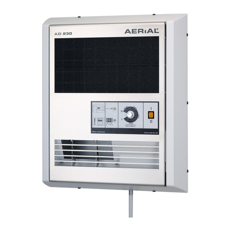
Aerial
Aerial AD 230 instruction manual
Andrews Dehumidification
Andrews Dehumidification HD 500 DV Operating instructions & safety guide
Toyotomi
Toyotomi TD-ZB80 user manual

Waykar
Waykar PD253B user manual
Haier
Haier HDN455 - 45 Pint Capacity Dehumidifier user manual
Trotec
Trotec TTK 650 S operating instructions
