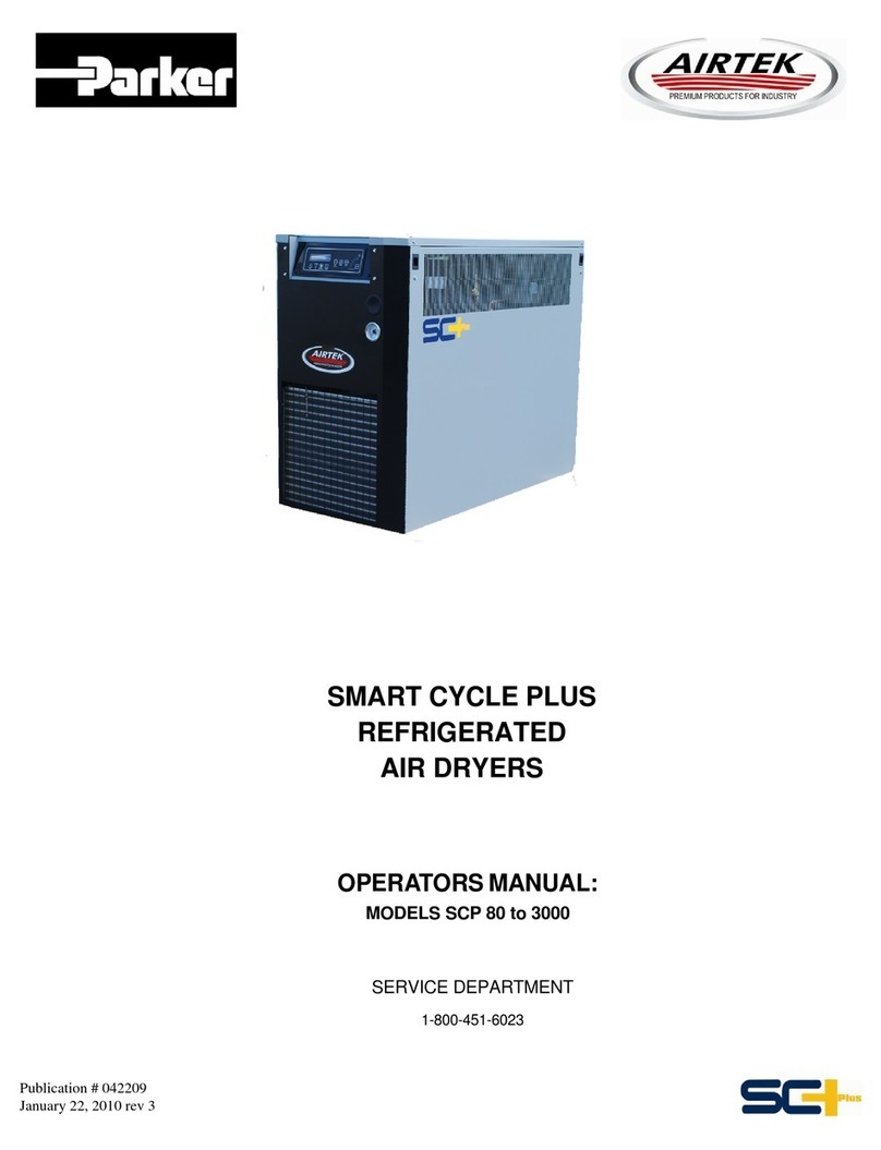
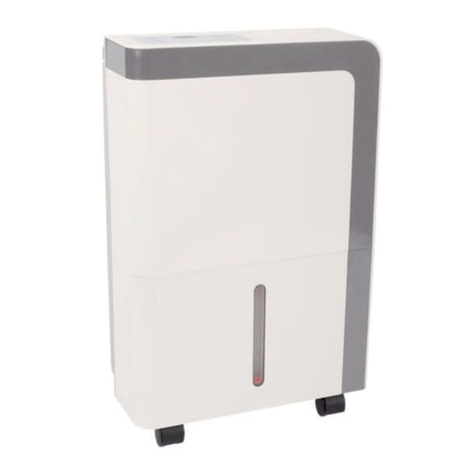
Parker Airtek MSC Series User manual

MSC Refrigerated Air Dryer
User Guide
Models MSC4000 to MSC15000

2
MSC4000 - MSC15000 USER GUIDE
Introduction Letter
Dear Customer,
Let us take this opportunity to introduce our company.
Parker is an innovative manufacturer of industrial equipment for compressed air
systems.
Our product line includes natural gas dryers, fluid coolers, water separators, air filters,
refrigerated air dryers, and heatless and heat reactivated desiccant air dryers. Our
products can be found in all corners of the world.
No effort has been spared to provide a comprehensive instruction manual for the use
of the Parker Dryer. Information is given not only for the user, but also for the technical
personnel who may repair the dryer in the event that this is ever necessary. It is
recommended that all who will have responsibility for the dryer carefully read all sections
of this manual before commencing with the installation.
The most important step is for you as a customer is to call us first at
716 686 6400 if you are experiencing a problem with your dryer.
If there is a question regarding this manual or our warranty policies and procedures,
please call. We would be happy to speak with you.
Thank you for choosing Parker products.
Parker Service Department

3
MSC4000 - MSC15000 USER GUIDE
Contents
1. Pre-Installation 4
1.1 Inspection, Handling and Setup 4
2. Dryer Installation 4
2.1 Location of Dryer 4
2.2 Outdoor Installation (Sheltered) 4
2.3 Airline Plumbing 5
2.4 Electrical Connections 5
3. Principle of Operation 6
4. Start Up Procedure 7
4.1 Preliminary Checks 7
4.2 Refrigeration Service Valves 7
4.3 Starting the Dryer 7
4.4 Start Up Checklist 9
4.5 Comments / Recommendations / Observations 10
5. Control Center 11
6. MRD Drains 29
7. Routine Maintenance 30
7.1 Maintenance Procedures 30
7.2 Routine Maintenance 31
8. For the Refrigeration Technician 33
8.1 Evaporator Leaks 33
8.2 Refrigerant Control Valves 34
8.3 Solenoid Valves 34
8.4 Drains 34
8.5 Electronic Controls 34
8.6 Factory Assistance 35
8.7 Instructions for Ordering Parts 35
8.8 Miscellaneous Dryer Data 35
9. Diagnostic Codes 36
9.1 Diagnostic Code “E1” Shutdown on Open Dew Point Circuit 36
9.2 Diagnostic Code “E2” Shutdown on Shorted Dew Point Circuit 36
9.3 Diagnostic Code “E3” Shutdown on High Super Heat 37
9.4 Diagnostic Code “E4” Shutdown on Freeze Protection 38
9.5 Diagnostic Code “E5” High Dew Point Shutdown 38
9.6 Diagnostic Code “E6” Shutdown on Low Suction PSI 40
9.7 Diagnostic Code “E7” Shutdown on High Head PSI 41
9.8 Diagnostic Code “E9” Drain Shutdown 43
10. Maintenance Charts 44
11. Warranty and Product Registration 45
12. Drawings & Spare Parts 46

4
MSC4000 - MSC15000 USER GUIDE
1. Pre-Installation
1.1 Inspection, Handling and Setup
Inspect the dryer carefully upon arrival and note any damage on the freight bill. File a notice of
concealed damage if: (1) there are any dents in the cabinet; (2) the air and drain pipes are not
straight; (3) there is any sign of oil on the skid oor. File these claims with the carrier immediately!
Cautions and Operating Warnings:
• Never work on unit under pressure
• Never work on unit when power is connected.
• Do not over-pressurize unit.
• Install unit in a clean, cool (50º - 95ºF / 10º - 35ºC); well lighted location
• Do not shut unit off at disconnect switch except during service. Unit must be
turned on and off by the panel switch located on the dryer.
• Do not operate dryer at abnormal conditions (high ow, high inlet temperature,
high ambient, high inlet pressure, etc.)
2. Dryer Installation
2.1 Location of Dryer
Unless supplied for special conditions, the air-cooled dryers must be located in an area with an
ambient temperature between 10ºC (50ºF) and 38ºC (100ºF), and free from explosive and corrosive
fumes. High ambient temperatures affect the outlet dew point of the dryer. For every 4ºC (39ºF)
of ambient temperature over 38ºC (100ºF), a decrease of 6% of dryer performance is encountered
with air-cooled dryers. The unit must not operate in an ambient of over 38ºC (100ºF). For ambient
conditions of over 38ºC (100ºF), water cooled dryers are suggested and are available upon
request.
2.2 Outdoor Installation (Sheltered)
There are certain items that should be incorporated into the system to help ensure trouble-free
operation.
The dryer should be on a concrete pad, which is designed to drain water away from it. If the
concrete pad is sloped, then the dryer must be mounted so that it is level. The base of the skid
must be sealed where it contacts the concrete pad.
If local weather conditions can be extreme such that direct rain or snow may fall on the unit, it
should be in a full enclosed room or building. The dryer must be protected from the elements.
If installed under a shelter, air-cooled machines must be positioned in a way that prevents air
recirculation.
If installation include more than one component, hot air exhaust should not be directed toward the
fresh air intake of the dryer.
A standard machine installed outside must not be started or run if the ambient temperature in and
around the dryer drops or may drop below 50ºF (10ºC).
CAUTION – Three feet of space must be allowed between all open grills and walls or other
objects. If the dryer is installed in a conned area, an exhaust system must be provided to avoid
excessive recirculation of hot room air.

5
MSC4000 - MSC15000 USER GUIDE
2.3 Airline Plumbing
All connections are made to the outside of the cabinet as follows:
• Plumbing must be supported independently of the dryer.
• If vibration is present, exible metal hoses must be installed to prevent it from being
transmitted to the dryer.
• Use unions or ange joints.
• Bypass piping around the dryer is recommended for ease in servicing or removal of unit if
necessary.
• Direction of ow through the dryer must be observed. A check valve on the outlet of the
dryer to prevent back ow and false loading is recommended.
NOTE: Use two wrenches when connecting to dryer piping so as to prevent damage to internal
air or water lines.
On water-cooled units, install a strainer. Minimum water pressure is 30 psi (2.1 bar g). Maximum
water inlet pressure is 150 psi g (10.4 bar g). Dryers are designed for inlet water temperature.
Higher water temperature reduces dryer capacity (consult the factory for water temperatures
above 85ºF (29ºC).
2.4 Electrical Connections
Before connecting electrical power to the dryer if applicable
• Check for correct voltage and phase at electrical connection box.
• Install a fused disconnect switch near the dryer.
• Connect power to the stripped leads located in the electrical connection box or to main
lugs of contactor, whichever is necessary.
• (NOTE: All units must be externally grounded to protect against the possibility of
severe electrical shock)
• CAUTION: Wire the dryer separately from the air compressor. The dryer must NOT cycle
on and off with the air compressor.
• Phase rotation is only important if the dryer has a 3-phase condenser fan. Fans must
PULL air through the condenser coil.
• Crankcase heaters are pre-wired at the factory to the line side of the terminal box or
contactor. Heaters must be energized at all times, therefore the main disconnect must be
left on except when servicing the dryer.
Parameter Concentration
Langelier Index 0 - 1
pH 7.5 - 9
Sulfate (SO) -24 < 50 ppm
Electrical Conductivity 10 - 500 μS/cm
Ammonia (NH3) < 1 ppm
Chloride (Cl) < 50 ppm
Total Hardness 70 - 150 ppm CaCO3
Oxygen < 0.1 ppm
Iron (Fe) < 0.2 ppm
Nitrate (NO3) < 2 ppm
Alkalinity (HCO) -3 70 - 300 ppm
Hydrogen Sulde (HS) 2 < 0.05 ppm
Free CO 2 < 5 ppm
Aluminum (Al) < 0.2 ppm
Condenser Cooling Water Pressure 30 - 150 psi g (2.1 - 10.4 bar g)

6
MSC4000 - MSC15000 USER GUIDE
3. Principle of Operation
The dryer is designed to operate automatically and continuously from no load to full load without freeze up.
Air System
The major air system components are the air-to-air PRECOOLER / REHEATER, the EVAPORATOR, and the
MECHANICAL SEPARATOR.
Hot, wet air enters the inlet of the precooler/reheater where it is cooled by the outgoing air. The air then
enters the evaporator where it is cooled by the refrigerant causing the air’s humidity to condense into liquid
water.
Next, the air travels to the separator. The air enters the separator where bulk oil and moisture are removed
from the air stream through a combination of centrifugal action and velocity reduction. After removal from
the air stream, all contaminants are ejected from the air system by automatic solenoid or oat drains.
From the separator, the cold dry air enters the outgoing side of the precooler/reheater where it is reheated
by the hot incoming air.
The precooler/reheater serves a triple purpose. By precooling the incoming air, it conserves refrigeration
use and by reheating the outgoing air, it serves to eliminate sweating of pipes in the plant air system. Most
important, it increases the temperature dew point split, preventing moisture from condensing out of the
compressed air when the air is expanded.
Warm Wet Air
Partially Cooled Air
Cold Wet Air
Dry Puried Air
Liquid Refrigerant
Cold Refrigerant Gas
Hot Refrigerant Gas

7
MSC4000 - MSC15000 USER GUIDE
4. Start Up Procedure
4.1 Preliminary Checks
Before starting the dryer, verify that the compressed air valves are closed so there is no airow
through the dryer, the dryer supply voltage is correct, and there is sufcient water supply to the
unit (water cooled). Also ensure unit is level at this time.
4.2 Refrigeration Service Valves
Open all valves marked with a “VALVE CLOSED” label.
Note: Always use a refrigeration service valve wrench on the spindles.
Remove the black plastic cap and completely backseat the valve spindle (counter clockwise) on
service valves and turn all 90 deg valves to the open position.
Note: Before replacing the caps, tighten the packing on all service valves.
4.3 Starting the Dryer
• Open the electrical panels and verify all electrical connections prior to powering up the dryer.
• Check and verify the service switch is in the “OFF” position.
• Close panels and supply power to the dryer.
• After power has been applied the control panel should say “OFF” and the crankcase heater
will now start heating.
• THE CRANKCASE HEATER MUST BE SWITCHED ON 12 HOURS BEFORE STARTING THE
DRYER. Failure to comply with this rule may cause serious damage to the compressor.
• Open the condenser water supply and return valves on water-cooled units.
• If necessary, bleed the air from the condenser water shell.
START THE DRYER BEFORE SUPPLYING AIR!
• Turn the service switch to the “ON” position. The refrigeration compressor may run
momentarily.
• Depress the “LOAD / UNLOAD” button to start the dryer.
• Verify correct rotation of fans on air-cooled units. There is no rotation that needs to be
checked on water-cooled units.
• Wait until the dryer reaches cycling temperatures and pressures.
Note: If the dryer overshoots the “OFF” temperature 30-32ºF (-1-0ºC) and you experience an
“E-1” alarm, SLOWLY pressurize the dryer by opening the compressed air inlet valve and verify
the cable connection as outlined in the operation and troubleshooting manual. Due to the thermal
bank effect of the ooded evaporator, it is normal for the dew point temperature to fall below the
“OFF” temperature after the refrigeration compressor shuts down with little or no load. The alarm
should clear once the dew point probe temperature rises into its operating range.
Verify the liquid level in the expansion tank sight glass for proper oil return! Adjustment is
usually not required, and the refrigerant level must be veried after 24 to 48 hours of operation.
Adjust as necessary, using the level control valve (TXV). Counterclockwise raises the level &
clockwise lowers the level. The oil level in the refrigeration compressor should be between ¼
and ¾ in the compressor sight glass. Contact Customer Service if there are ANY questions. The
refrigerant level will rise and fall during normal operation.
CAUTION: If liquid level is not operating within this site glass, there will be insufcient oil return
and refrigerant compressor damage will result. If there is excessive liquid (overll) in the expansion
tank, there will be liquid ood-back and refrigerant compressor damage will result.
• SLOWLY open the air inlet valve gradually to pressurize the dryer if this has not already been
done.
• SLOWLY open the air outlet valve.
8
MSC4000 - MSC15000 USER GUIDE
• SLOWLY close the air bypass valve until the dryer is under an air load.
Note: Fast opening of air valves could damage the heat exchangers. At this time, complete the
following start up form.
Note: The refrigerant compressor may require additional oil added. Oil level will need to be veried
at the same time as the expansion tank refrigerant level (within 24 to 48 hours) to ensure correct
system operation and adjustment.
For units supplied with Refrigeration Oil Separator (STD on Water cooled units – MSC12000
& UP and STD on Air cooled MSC10000 & UP)
• Change oil separator element 24-48 hours after initial start-up.
• An extra element for this change out is supplied with shipment.

9
MSC4000 - MSC15000 USER GUIDE
4.4 Start Up Checklist

10
MSC4000 - MSC15000 USER GUIDE
4.5 Comments / Recommendations / Observations
Comments / Recommendations / Observations
_
__
__
__
__
__
__
__
__
__
__
__
__
__
__
__
__
__
__
__
__
__
__
__
__
__
__
__
__
__
__
__
__
__
__
__
__
__
__
__
__
__
__
__
__
__
__
_
_
__
__
__
__
__
__
__
__
__
__
__
__
__
__
__
__
__
__
__
__
__
__
__
__
__
__
__
__
__
__
__
__
__
__
__
__
__
__
__
__
__
__
__
__
__
__
_
_
__
__
__
__
__
__
__
__
__
__
__
__
__
__
__
__
__
__
__
__
__
__
__
__
__
__
__
__
__
__
__
__
__
__
__
__
__
__
__
__
__
__
__
__
__
__
_
_
__
__
__
__
__
__
__
__
__
__
__
__
__
__
__
__
__
__
__
__
__
__
__
__
__
__
__
__
__
__
__
__
__
__
__
__
__
__
__
__
__
__
__
__
__
__
_
_
__
__
__
__
__
__
__
__
__
__
__
__
__
__
__
__
__
__
__
__
__
__
__
__
__
__
__
__
__
__
__
__
__
__
__
__
__
__
__
__
__
__
__
__
__
__
_
_
__
__
__
__
__
__
__
__
__
__
__
__
__
__
__
__
__
__
__
__
__
__
__
__
__
__
__
__
__
__
__
__
__
__
__
__
__
__
__
__
__
__
__
__
__
__
_
_
__
__
__
__
__
__
__
__
__
__
__
__
__
__
__
__
__
__
__
__
__
__
__
__
__
__
__
__
__
__
__
__
__
__
__
__
__
__
__
__
__
__
__
__
__
__
_
_
__
__
__
__
__
__
__
__
__
__
__
__
__
__
__
__
__
__
__
__
__
__
__
__
__
__
__
__
__
__
__
__
__
__
__
__
__
__
__
__
__
__
__
__
__
__
_
_
__
__
__
__
__
__
__
__
__
__
__
__
__
__
__
__
__
__
__
__
__
__
__
__
__
__
__
__
__
__
__
__
__
__
__
__
__
__
__
__
__
__
__
__
__
__
_
_
__
__
__
__
__
__
__
__
__
__
__
__
__
__
__
__
__
__
__
__
__
__
__
__
__
__
__
__
__
__
__
__
__
__
__
__
__
__
__
__
__
__
__
__
__
__
_
_
__
__
__
__
__
__
__
__
__
__
__
__
__
__
__
__
__
__
__
__
__
__
__
__
__
__
__
__
__
__
__
__
__
__
__
__
__
__
__
__
__
__
__
__
__
__
_
_
__
__
__
__
__
__
__
__
__
__
__
__
__
__
__
__
__
__
__
__
__
__
__
__
__
__
__
__
__
__
__
__
__
__
__
__
__
__
__
__
__
__
__
__
__
__
_
_
__
__
__
__
__
__
__
__
__
__
__
__
__
__
__
__
__
__
__
__
__
__
__
__
__
__
__
__
__
__
__
__
__
__
__
__
__
__
__
__
__
__
__
__
__
__
_
_
__
__
__
__
__
__
__
__
__
__
__
__
__
__
__
__
__
__
__
__
__
__
__
__
__
__
__
__
__
__
__
__
__
__
__
__
__
__
__
__
__
__
__
__
__
__
_
_
__
__
__
__
__
__
__
__
__
__
__
__
__
__
__
__
__
__
__
__
__
__
__
__
__
__
__
__
__
__
__
__
__
__
__
__
__
__
__
__
__
__
__
__
__
__
_
_
__
__
__
__
__
__
__
__
__
__
__
__
__
__
__
__
__
__
__
__
__
__
__
__
__
__
__
__
__
__
__
__
__
__
__
__
__
__
__
__
__
__
__
__
__
__
_
_
__
__
__
__
__
__
__
__
__
__
__
__
__
__
__
__
__
__
__
__
__
__
__
__
__
__
__
__
__
__
__
__
__
__
__
__
__
__
__
__
__
__
__
__
__
__
_
_
__
__
__
__
__
__
__
__
__
__
__
__
__
__
__
__
__
__
__
__
__
__
__
__
__
__
__
__
__
__
__
__
__
__
__
__
__
__
__
__
__
__
__
__
__
__
_
_
__
__
__
__
__
__
__
__
__
__
__
__
__
__
__
__
__
__
__
__
__
__
__
__
__
__
__
__
__
__
__
__
__
__
__
__
__
__
__
__
__
__
__
__
__
__
_
_
__
__
__
__
__
__
__
__
__
__
__
__
__
__
__
__
__
__
__
__
__
__
__
__
__
__
__
__
__
__
__
__
__
__
__
__
__
__
__
__
__
__
__
__
__
__
_
_
__
__
__
__
__
__
__
__
__
__
__
__
__
__
__
__
__
__
__
__
__
__
__
__
__
__
__
__
__
__
__
__
__
__
__
__
__
__
__
__
__
__
__
__
__
__
_
_
__
__
__
__
__
__
__
__
__
__
__
__
__
__
__
__
__
__
__
__
__
__
__
__
__
__
__
__
__
__
__
__
__
__
__
__
__
__
__
__
__
__
__
__
__
__
_
_
__
__
__
__
__
__
__
__
__
__
__
__
__
__
__
__
__
__
__
__
__
__
__
__
__
__
__
__
__
__
__
__
__
__
__
__
__
__
__
__
__
__
__
__
__
__
_
_
__
__
__
__
__
__
__
__
__
__
__
__
__
__
__
__
__
__
__
__
__
__
__
__
__
__
__
__
__
__
__
__
__
__
__
__
__
__
__
__
__
__
__
__
__
__
_
_
__
__
__
__
__
__
__
__
__
__
__
__
__
__
__
__
__
__
__
__
__
__
__
__
__
__
__
__
__
__
__
__
__
__
__
__
__
__
__
__
__
__
__
__
__
__
_
_
__
__
__
__
__
__
__
__
__
__
__
__
__
__
__
__
__
__
__
__
__
__
__
__
__
__
__
__
__
__
__
__
__
__
__
__
__
__
__
__
__
__
__
__
__
__
_
_
__
__
__
__
__
__
__
__
__
__
__
__
__
__
__
__
__
__
__
__
__
__
__
__
__
__
__
__
__
__
__
__
__
__
__
__
__
__
__
__
__
__
__
__
__
__
_
_
__
__
__
__
__
__
__
__
__
__
__
__
__
__
__
__
__
__
__
__
__
__
__
__
__
__
__
__
__
__
__
__
__
__
__
__
__
__
__
__
__
__
__
__
__
__
_
_
__
__
__
__
__
__
__
__
__
__
__
__
__
__
__
__
__
__
__
__
__
__
__
__
__
__
__
__
__
__
__
__
__
__
__
__
__
__
__
__
__
__
__
__
__
__
_
_
__
__
__
__
__
__
__
__
__
__
__
__
__
__
__
__
__
__
__
__
__
__
__
__
__
__
__
__
__
__
__
__
__
__
__
__
__
__
__
__
__
__
__
__
__
__
_
_
__
__
__
__
__
__
__
__
__
__
__
__
__
__
__
__
__
__
__
__
__
__
__
__
__
__
_
Completed By: (Print) ___________________________
Cert.# (REQUIRED)______________________________
Signature: _____________________________________
C
Cu
us
st
to
om
me
er
rS
Si
ig
gn
na
at
tu
ur
re
e:
:_
__
__
__
__
__
__
__
__
__
__
__
__
__
__
__
__
__
__
__
__
__
__
__
__
__
__
__
_

11
MSC4000 - MSC15000 USER GUIDE
5. Control Center
PREFACE:
This document is intended to make familiar, the Control Center functionality. The “manual”, can serve as
a handy guide to quickly move through the operations of the dryer it is controlling. It is not intended to
replace the more comprehensive, specic “dryer manual” that will show all other aspects of operation and
safety. It is IMPORTANT that both manuals be referenced for complete dryer understanding.
MENU TREE
a. STARTUP NULL SCREEN--------------------------------------------------------------------[ 4 ]
• PRE-SETUP
• STARTUP
• CHANGE MODES
b. MAIN SCREEN------------------------------------------------------------------------------[ 5 ]
• DISPLAY ORIENTATION
• TYPICAL SCREEN DISPLAYS
c. EVENTS-------------------------------------------------------------------------------------[ 6 ]
• EMERGENCY STOP
• STANDBY
• DEW POINT OPTION (not installed)
• ACTIVE ALARMS
• DEW POINT ALARMS
• NO FLOW
d. REVIEW ALARM LOG (“J” Series Menus)--------------------------------------------------[ 6 ]
e. DISPLAY SENSOR VALUES (“K” Series Menus)-------------------------------------------[ 8 ]
• FLOW METER (4-20 mA/1 to 5 volt INPUT)
MAIN MENU
1 DEW POINT SETTINGS (“D” Series Menus)--------------------------------------------------[ 9 ]
• DEW POINT SETPOINT
2. SETUP MENU (“E” Series Menus)----------------------------------------------------------[ 10 ]
• COMPANY INFORMATION-----------------------------------------------------------------[ 10 ]
PHONE & www MESSAGE
• PRODUCT INFORMATION-----------------------------------------------------------------[ 10 ]
TYPE OF DRYER & SN#
FACTORY DEFAULTS
GO TO “NULL” STATE
CALIBRATION MENU (“H” Series Menus)
INLET PRESSURES
REHEATER PRESSURE
OUTLET PRESSURE
DISCHARGE PRESSURE
SUCTION PRESSURE
ELEMENT DP SETTINGS

12
MSC4000 - MSC15000 USER GUIDE
FLOW RANGE SETTINGS
• DRAINS SETUP MENU (“I” Series Menus)----------------------------------------------[ 12 ]
#1 DEMAND or TIMED OPERATIONS
#1 INTERVAL (Timed)
#1 DURATION
#1 AUTOTEST
#2 DEMAND or TIMED OPERATIONS
#2 INTERVAL (Timed)
#2 DURATION
#2 AUTOTEST
• COMMUNICATON MENU (“F” & “G” Series Menus)--------------------------------------[ 12 ]
ADJUST CLOCK
STAR WATCH – Host to Control: YES
MODEM SETUP
MODEM ENABLE
MODEM TEST
MODEM RESET (Reprogram)
VIEW MODEM SETTINGS
3. SENSOR SETTINGS (“C” Series Menus)---------------------------------------------------[ 14 ]
• P1: LOW INLET PRESSURE
• P1: HIGH INLET PRESSURE
• P2: REHEATER PRESSURE
• P3: OUTLET PRESSURE
• P4: DISCHARGE PRESSURE
• P5: SUCTION PRESSURE
• P6: SEPARATOR DP
• FLOW
4. TEMPERATURE SETTINGS (“B” Series Menus)--------------------------------------------[ 15 ]
• T1: DRYER INLET SETPOINT
• T2: PRECOOLER SETPOINT
• T3: DRYER OUTLET SETPOINT
• T4: REFRIGERANT SETPOINT
• T5: SUCTION SETPOINT
• T6: AMBIENT/H2O SETPOINT
5. VIEW ALARMS (“A” Series Menus)--------------------------------------------------------[ 15 ]
• HIGH DEW POINT
• LOW FLOW
• (E1/E2) DEW POINT PROBE FAULT (OPEN OR SHORT)
• MOTOR OVERLOAD
• (E3) SUPERHEAT OUT OF RANGE
• (E4) LOW DEW POINT
• (E5) DRYER OVERLOAD
• (E6) LOW FREON OR OIL PRESSURE
• (E7) HIGH FREON PRESSURE
• (W1) LOW AIR-IN PSI
• (W2) HIGH AIR-IN PSI
• (W4) HIGH INLET AIR TEMP
• (W5) HIGH AMBIENT/H2O TEMP
• (W6) DRAIN FAULT
• MODEM FAULT

13
MSC4000 - MSC15000 USER GUIDE
1. Up Arrow
2. Down Arrow
3. Set
4. Reset Alarm
5. Load/Un-Load
6. Thermal Bank
7. Auto Run
8. Drain Test
9. Display Values
10. Review Alarm Log
Scroll Menu Up or Increment Value
Scroll Menu Down or Decrement Value
Enter Menu Selection, Enter Program Mode or Save to Memory
Back-up Menu Level or Clear ‘Resetable’ Alarm
Load/Un-Load Mode Selector
Thermal Bank Mode Selector
Auto Mode Selector – Automatically Sequences to Demand (#5 or #6)
Operates Both Drain System for Programmed Duration
Enters Sensor Menus – Indicates Current Values (Series ‘K’ Screens)
Enters Historical Log of Alarm Event (Series ‘J’ Screens)

14
MSC4000 - MSC15000 USER GUIDE
a. STARTUP NULL SCREEN------------------------------------------------------------------
Upon initialization, the display shows the “type” of dryer the Control Center is congured to control. An
example:
Company
REFRIG DRYER (R404A)
S/N B00001 V2.12IR4
This is a fixed configuration. Once assigned to a dryer: the Control Center will never be changed to
any of the other configurations. Note that the Control Center Serial Number,Refrigerant Type and
Firmware Version are also displayed on the null, initialization screen.
PRE-SETUP
Prior to starting up the dryer, the DISPLAY VALUES button may be selected to
view groupings of sensors (use the up/down arrows to scroll through the list)
Depress the Display Values button a second time, or the Alarm RESET button to
return to the Main Screen. Also, all of the other screens and menus can be viewed
by using the up/down arrows. Simply position any particular menu choice into
view and advance a menu level by depressing the SET button. Returning to the Main
Screen can be achieved at any time by depressing the Alarm RESET button.
These screens may be viewed at any time, and at any state of operation.
The Main Screen of the Fan Inactive System prior to start-up (run mode) is the NULL Screen above, when
returning to the Main Screen from viewing any of the above Pre-Startup
procedures.
STARTUP
TO START the dryer, select any of three main operating modes by depressing
their button.
• AUTO Mode (normal operations) dryer will automatically sequence between the Load/Un-Load
and Thermal Bank modes as required by demand.
• LOAD/UN-LOAD Mode (cycling operation), or
• THERMAL BANK Mode (cycling operation including compressor including OFF).
CHANGING MODES
The dryer can change modes of operation by simply depressing the any desired
mode button. To return the dryer to an INACTIVE (SYSTEM OFF-STANDBY) state, depress, the “current
mode” button as is indicated by the Mode Pilot
indicator (LED).
b. MAIN SCREEN---------------------------------------------------------------
DISPLAY ORIENTATION
There are several informational indications displayed on the Main Screen. They are displayed
on the four lines of the LCD.
1. The rst line is the “message” line. If all is normal, this line will indicate ALL SYSTEMS
OK, or else it will indicate an alarm; for example, HIGH DEW POINT. If more than one
alarm is active, this message line will “scroll” between any and all messages.

15
MSC4000 - MSC15000 USER GUIDE
2. The second line is the “mode” line. This line will indicate the dryers operations:
• SYSTEM INACTIVE (NULL),
• EMERGENCY STOP,
• AUTO RUN MODE
• LOAD/UN-LOAD MODE,
• THERMAL BANK MODE,
• SYSTEM OFF, and
• ALARM SHUT DOWN
3. The third line is the “process” line. INITIALIZING, POWERSAVE ACTIVE or may be blank for all
other normal operations.
4. The forth line is dedicated to the current DEW POINT value.
TYPICAL SCREEN DISPLAYS-----------------------------------------------------------------------------
Below is a sampling of typical display screens; showing some of the possible
system operations.
ALL SYSTEMS OK
AUTO RUN MODE
POWERSAVE ACTIVE
DEW POINT 34ºF (1ºC)
MOTOR OVERLOAD
ALARM SHUTDOWN
DEW POINT 39ºF (4ºC)
ALL SYSTEMS OK
SYSTEMS OFF
DEW POINT 65ºF (18ºC)
COMPRESSOR WILL
CONTINUE TO RUN
UNTIL PUMPDOWN
IS COMPLETE
STARWATCH ACTIVE
AUTO RUN MODE
DEW POINT 33ºF (0ºC)
ACTIVE ALARMS
EMERGENCY STOP!
DEW POINT 35ºF (2ºC)
c. EVENT---------------------------------------------------------------------------------------
EMERGENCY STOP At any time the dryer’s E-STOP pushbutton is depressed, the
dryer will immediately “stop” operations (all output will be de-energized except
for COMMON ALARM dry output relay and MODEM relay). To restart the dryer, the
ashing mode (AUTO RUN, LOAD/UNLOAD or THERMAL BANK) selector must be
re-selected. Note – the E-STOP pushbutton must be rotated and pulled “out” to
its normal position before the re-start can be invoked.

16
MSC4000 - MSC15000 USER GUIDE
LOW FREON/OIL PSI
ALARM SHUT DOWN
DEW POINT 35ºF (2ºC)
J1 ALARM LOG
HIGH DEW POINT
DAYS SINCE LAST: 1
ALARM OUT: YES
J2 ALARM LOG
LOW FLOW
DAYS SINCE LAST: 25
ALARM OUT: YES
J3 ALARM LOG
DP PROBE DEFAULT
DAYS SINCE LAST: 365
ALARM OUT: YES
J4 ALARM LOG
MOTOR OVERLOAD
DAYS SINCE LAST: ---
ALARM OUT: YES
ALARM SHUT DOWN When a “shut-down” alarm occurs, the dryer will “stop
operating and will require a Manual Reset (see VIEW ALARMS section). Once
the alarm has been reset and if the alarm condition has been cleared, the system
may be re-started. The current mode LED will be ashing. When the mode selector
button is depressed, the system will restart and LED will stop ashing and
remain illuminated.
IMPORTANT
All screens from section (d.) forward to the end of this manual are indicated with an alphanumeric indication
in the upper left corner of the display as a screen ID. The CONTR
d. REVIEW ALARM LOG (“J” Series Menus)-------------------------------------------------------------
When the Review Alarm Log pushbutton is depressed, the “J” series screens will be displayed.
Each “J” screen shows the status of a possible alarm. The UP/DOWN arrow will allow
scrolling through 16 different alarm conditions. The number appearing next the “DAYS
SINCE LAST”, indicated the last time that the alarms condition has occurred. A zero (0)
indicates the current date. For example, 365 would indicate exactly one year since the
occurrence of any particular alarm. If “---“ is indicated, that means the selected alarm
All screens from section (d.) forward to the end of this manual are indicated with an alphanumeric indication
in the upper left corner of the display as a screen ID. The CONTROL CENTER will display these ID’s as
any given screen is selected within the menu tree. Please make note of any particular screen ID when
communicating with a support representatives, which may be in question.
When an alarm is tripped, the “COMMON ALARM RELAY” (K16) will energize if the “ALARM OUT” is
ENABLED. There is a form “C” dry contact available for the user on K16 (see schematic). To “DISABLE”
the ALARM OUT from energizing the Common Alarm relay, use the SET and UP/DOWN arrow buttons to
disable any given alarm. All alarms are factory default to “ENABLED”. The used can program anyone, any
combination, or all alarms to activate the Common Alarm relay.

17
MSC4000 - MSC15000 USER GUIDE
J5 ALARM LOG
E3: HI SUPERHEAT
DAYS SINCE LAST: ---
ALARM OUT: YES
J6 ALARM LOG
E4: DRYER OVERLOAD
DAYS SINCE LAST: ---
ALARM OUT: YES
J7 ALARM LOG
E5: LOW PRESSURE
DAYS SINCE LAST: ---
ALARM OUT: YES
J8 ALARM LOG
E6: LOW PRESSURE
DAYS SINCE LAST: 0
ALARM OUT: YES
J9 ALARM LOG
E7: HIGH PRESSURE
DAYS SINCE LAST: ---
ALARM OUT: YES
J9 ALARM LOG
E7: HIGH PRESSURE
DAYS SINCE LAST: ---
ALARM OUT: YES
J10 ALARM LOG
W1 LOW AIR-IN PSI
DAYS SINCE LAST: 54
ALARM OUT: YES
J11 ALARM LOG
W2: HIGH AIR-IN PSI
DAYS SINCE LAST: ---
ALARM OUT: ENABLED
J12 ALARM LOG
W3: CHANGE FILTER
DAYS SINCE LAST: ---
ALARM OUT: YES
J13 ALARM LOG
W4: HIGH AIR-IN ºF
DAYS SINCE LAST: ---
ALARM OUT: YES
J14 ALARM LOG
W5: HIGH AMBIENT/H2O
DAYS SINCE LAST: ---
ALARM OUT: YES
J15 ALARM LOG
E9: DRAIN FAULT
DAYS SINCE LAST: ---
ALARM OUT: YES
J16 ALARM LOG
MODEM FAULT
DAYS SINCE LAST: 1
ALARM OUT: YES
LOW REFRIGERANT/OIL PRESSURE
NOTE: IF MULTIPLE COMPRESSORS – SEE ACTIVE ALARMS

18
MSC4000 - MSC15000 USER GUIDE
K1 Superheat 12ºF
T4: Refrig 130ºF
P4: Discharge 100 psi
P5: Suction 96 psi
R TYPE: R404A
K2 Superheat 12ºF
T5: Suction 100ºF
P5: Suction 100 psi
K3 Dewpoint 33ºF
T1: Inlet 100ºF
P1: Inlet 100 psi
T6: Ambient/H2O of 54ºF
K4
P1: Inlet 100 psi
P1: Outlet 98 psi
P6: Filter Element OK
K5
T1: Inlet 100ºF
T3: Outlet 90ºF
K6
T6: Ambient/H2O of 67ºF
P4: Discharge 250 psi
-Flow 10000 scfm
K7 T1: Inlet 100ºF
T3: Outlet 90ºF
PI: Inlet 100 psi
P3: Outlet 98 psi
K8
Auxiliary #1 DISABLED
Auxiliary #2 75
Flow DISABLED
K9 Power: 10.4 Kw
Current: 12.4 A
Speed: 13000 RPM
Frequency: 45 Hz
K10 COMPRESSORS
Timer: 23:59 h:m
C1: STNDBY C2: ONLINE
C3: ONLINE C4: DISABL
E. DISPLAY SENSOR VALUES (“K” Series Menus)---------------------------------------------------
The DISPLAY VALUE pushbutton is a quick way to view groupings of sensor values. The
UP/DOWN arrows will scroll through the 7 possible groups of the “K” series screen.
NOTE IF NOT “OK” = CHANGE FILTER WILL BE INDICATED
CUSTOM ENGINEERED UNITS
NOTE Auto-Sequence “Time” can be selected between
1 & 72 hours. (See Compressor Menu’s R1 – R5 to
ENABLE or DISABLE by pressing the SET.
FLOW METER:
All Control Center’s come standard with ow sensor input capabilities. Simply “hook-up” a 4-20 mA loop, or a 1
to 5 volt signal to the appropriate ow input (see schematic/wiring diagram)and activate the FLOW ENABLE in the
SETUP screens. The loop may be powered by the Control Center or powered externally. The FLOW measurement
is displayed in the “K6” screen only if enabled. Refer to schematic for conguring panel to “current/voltage” only if
enabled. Call support for details or questions.

19
MSC4000 - MSC15000 USER GUIDE
DEW POINT
MENU
Press SET to Select
D1 DEW POINT
Value: 36ºF
Set Point: 34ºF
SETUP
MENU
Press SET to Select
E2 PRODUCT INFORMATION
Press SET to select
E2 CT (404A)
REFRIG AIR DRYER
Serial # B00000
Firmware Rev. 2.38
E3 COMMUNICATIONS
MENU
Press SET to Select
E4 DRAIN SETUP
MENU
Press SET to select
1. DEW POINT MENU-----------------------------------------------------------------------------------
2. SETUP MENU--------------------------------------------------------------------------------------------
Screen series: “E”, “F”, “G”, “R” and “I” are within the set-up selections.
DEW POINT – The dryer will attempt to deliver a dew point relative to the DEW POINT SET POINT value.
The range for this setting can be selected between 34ºF (1ºC) to 50ºF (10ºC). When the dew point
indicated is at the set point value or less, the panel LCD display will give a message: POWERSAVE ACTIVE

20
MSC4000 - MSC15000 USER GUIDE
E5
CALIBRATION
MENU
E6 ALARM REPORTING
M1 ALARM #1
HIGH DEW POINT
RELAY PAGER REMOTE
Yes N/A N/A
M4 ALARM #2
FLOW/AUX
RELAY PAGER REMOTE
Yes N/A N/A
M7 ALARM #3
DP PROBE FAULT
RELAY PAGER REMOTE
Yes N/A N/A
M10 ALARM #4
MOTOR FAULT
RELAY PAGER REMOTE
Yes N/A N/A
M13 ALARM #1
E3: HI SUPERHEAT
RELAY PAGER REMOTE
Yes N/A N/A
M16 ALARM #6
E4: LOW DP/PUMPDOWN
RELAY PAGER REMOTE
Yes N/A N/A
M19 ALARM #7
E5: DRYER OVERLOAD
RELAY PAGER REMOTE
Yes N/A N/A
M22 ALARM #8
E6: LOW PRESSURE
RELAY PAGER REMOTE
Yes N/A N/A
M25 ALARM #9
E7: HIGH (REFRIG) PRESSURE
RELAY PAGER REMOTE
Yes N/A N/A
M28 ALARM #10
W1: LOW AIR-IN PSI
RELAY PAGER REMOTE
Yes N/A N/A
M31 ALARM #11
W2: HIGH AIR-IN PSI
RELAY PAGER REMOTE
Yes N/A N/A
M34 ALARM #12
W3: CHANGE FILTER
RELAY PAGER REMOTE
Yes N/A N/A
This manual suits for next models
2
Table of contents
Other Parker Dehumidifier manuals

Parker
Parker CDAS HL 050 Series Manual

Parker
Parker CDAS HL 050 Series User manual

Parker
Parker K-MT 1-8 User manual

Parker
Parker Airtek SMART CYCLE PLUS 80 User manual

Parker
Parker Airtek MSC4000 User manual

Parker
Parker DME012-RX User manual

Parker
Parker HDK-CNG Series User manual

Parker
Parker DTX 10 User manual

Parker
Parker Domnick Hunter PNEUDRI DME012 User manual

Parker
Parker Airtek TW 10 Instruction manual