Dectron DS Series User manual

DEHUMIDIFIERS
DS SERIES
Outdoor
Dectron.com
OPERATION AND MAINTENANCE MANUAL

Table of Content
General Information....................................................................................................................... 3
Operating Safety (Warnings, Cautions, and Notes)...................................................................................3
Reference and Additional Information......................................................................................................4
Basic Information.......................................................................................................................................5
Dehumidifier External Systems Connection –SLX Cab..............................................................................6
Dehumidifier External Systems Connection –BX Cab...............................................................................9
Layout and Components .............................................................................................................. 14
Dehumidifier Main Components - SLX.....................................................................................................14
Dehumidifier Main Components - BX......................................................................................................16
Control System.........................................................................................................................................18
Sequence of Operation –4 to 7 tons........................................................................................... 23
Ventilation. ..............................................................................................................................................23
Space Heating ..........................................................................................................................................23
Air Conditioning, Dehumidification and Pool Heating.............................................................................23
Compressor(s)..........................................................................................................................................23
Sequence of Operation –8 to 20 tons......................................................................................... 25
Ventilation. ..............................................................................................................................................25
Purge (Additional Exhaust) Option. .........................................................................................................25
Heat Recovery Option..............................................................................................................................26
Air Conditioning, Dehumidification and Pool Heating.............................................................................26
Compressor(s)..........................................................................................................................................27
Space Heating ..........................................................................................................................................28
Interface and Communication ..................................................................................................... 29
Touch Display Operator Panel .................................................................................................................29
Remote Communication..........................................................................................................................31
Basic Maintenance ....................................................................................................................... 32
Maintenance and Safety..........................................................................................................................32
Maintenance Key Points..........................................................................................................................32
Specific Components Maintenance.........................................................................................................34

Dectron DS Series –Outdoor OMM 2September 2020
Special Maintenance Tasks. Fluid Cooler Winterization. ........................................................................35
Pools –Equipment Warranty....................................................................................................... 36

September 2020 3Dectron DS Series –Outdoor OMM
General Information
This manual provides basic information about the applicable dehumidifier and its operation.
Important information regarding installation, maintenance, and start up as well as additional and auxiliary systems
and devices (outdoor condenser, communication interfaces, etc.) is normally provided with the dehumidifier and
can also be obtained at manufacturer (see Contact Us below).
Operating Safety (Warnings, Cautions, and Notes)
FOR YOUR SAFETY: READ BEFORE PERFORMING ANY OPERATIONS, MAINTENANCE OR SERVICE TASKS!
Only qualified technicians should install, operate, maintain or service mechanical equipment
including current dehumidification system.
Make sure to read this manual before performing any tasks to familiarize yourself with the
equipment as well as with any potential hazards. Always exercise caution!
Beware of electrical power and high electrical voltage!
•Follow proper safety procedures –lockout, tagout, and other respective procedures
•Failure to follow safety procedures can result in serious injury or death
Beware of moving parts and hot surfaces!
•Make sure to stop all moving parts (fans, blowers, etc.) before accessing the equipment’s
internal space
•Be aware of hot surfaces (hot refrigeration, space heating pipes, coils, heaters, etc.)
Beware of high pressures and chemicals!
•Dehumidifiers, equipped with compressors, contain refrigerant under high pressure; oil is
also contained in the compressor and refrigeration circuit(s)
•Some dehumidifiers may also contain other liquids such as glycol mixtures and pool water
The following warnings, cautions, and notes appear throughout this manual and referenced documentation
whenever special care must be taken to avoid potential hazards that could result in equipment malfunction or
damage, personal injury, or death.
WARNING
Indicates a potentially hazardous
situation which could result in
serious injury or death if handled
improperly.
CAUTION
Indicates a potentially hazardous
situation which could result in
moderate injury or equipment
damage if handled improperly.
Note
Indicates a situation that could
result in equipment damage or
improper/ineffective operation if
handled improperly.

Dectron DS Series –Outdoor OMM 4September 2020
Reference and Additional Information
For safe, efficient and problem-free operation, it is critical to handle the dehumidifier (as well as related systems
and components) properly at each step - from receiving and storage to installation and start up. Relevant
information can be found in the respective documents (like Installation Manual) provided with the dehumidifier.
This manual and other related documents could be obtained from the manufacturer (see Contact Us below).
Contact Us
Dectron
5685 Rue Cypihot
Saint Laurent QC, H4S1R3
Canada
Dectron.com
1-833-DAS-POOL (327-7665)
Schedule / Modify a Start-up:
Startups@DehumidifiedAirServices.com
Inquire about Warranty:
Warra[email protected]
Order Parts:
Parts@DehumidifiedAirServices.com
All Other Product Support:
Support@DehumidifiedAirServices.com
Attention: Installation and Service Contractors
WARNING! Any work (installation, start up, service, maintenance, repair, etc.) on any mechanical
equipment (dehumidifier, outdoor condenser, fluid cooler, etc.) must be performed in accordance with
respective manufacturer’s recommendations as well as submittal documentation, local Codes and Regulations,
and appropriate field practices. Failure to do so could result in personal injury, equipment damage or
malfunction, and will void equipment warranty. Only qualified and properly trained individuals should perform
tasks on this equipment.
Attention: Maintenance Team
CAUTION. To ensure equipment longevity and proper and efficient operation, the dehumidifier and its
auxiliary systems and devices (outdoor condenser, fluid cooler, boiler package, etc.) should be maintained
properly and regularly. Failure to do so could negatively affect premise comfort levels and people’s health. It
could also lead to equipment damage, malfunction, premature tear and ware and may void equipment warranty.

September 2020 5Dectron DS Series –Outdoor OMM
Basic Information
Dehumidifier View and Options –SLX Cab
Standard DS020 –DS035 outdoor packaged dehumidifier’s general views and options* are shown on Pic.C.1.
* All available options (tonnage, ductwork connections, other options) are shown. Refer to the submittal and
other relevant documentation for your equipment options, dimensions etc.
** The pool water heating option relies on compressor-created excess heat and is used as an additional
heating source. It does not eliminate the need for a main pool water heater.
*** For specific details on space heating (hot water, gas, electric) option, refer to the submittal and other
documentation:
•Electric heater or hot water coil, depending on (capacity, model, size, etc., can be installed externally (fitted in the
supply air ductwork) or internally. Refer to your dehumidifier’s submittal documentation
•Gas-fired heater can be installed externally (within supply ductwork). Alternatively, the dehumidifier could be provided
with Outdoor Gas Heater package (dehumidifier with package is shown on Pic. C.2 below):
**** Built-in (packaged) Outdoor Condenser is standard option, however dehumidifier could be provided with
remote AC option as well (remotely installed Outdoor Condenser or Fluid Cooler).
Options:
•Outdoor, single-compressor dehumidifiers
4 to 7 tons’ capacity *.
•Return Air (RA) ductwork connection
options –bottom, left, horizontal.
•Supply Air (SA) ductwork connection
options –bottom, horizontal*.
•Outdoor Air (OA) intake - horizontal*.
•Optional Exhaust Air (EA) –horizontal*.
•Optional Pool Water Heating **.
•Optional Space Heating - hot water coil,
electric or gas heater ***.
•Packaged Air Conditioning (AC) option –
built-in Outdoor Air-Cooled Condenser
(OACC).****
Pic. C.1

Dectron DS Series –Outdoor OMM 6September 2020
This configuration somewhat
limits the RA and SA options –refer
to your dehumidifier submittal.
Outdoor gas heater package
can also accommodate optional Full
Flow Pool Water Heater –refer to
submittal documentation for such
option additional details.
Dehumidifier External Systems Connection –SLX Cab
Pic. C.1 shows provisions for external systems connections, including ductwork, electric power and control wires
and various piping connections.
•Except for the condensate, all other piping systems are optional and may not be present in each dehumidifier.
•Electrical Power to be brought to the dehumidifier disconnect.
•Pool Heating and Space Heating water connections, as well as control wiring, are normally brought through
the pipe chase, located in the compressor compartment floor.
•Remote AC option (Outdoor Condenser or Fluid Cooler) piping connection: top (same as packaged AC option).
•Gas line. If the dehumidifier is equipped with a gas heater package for space heating purposes, the gas line
connection is to be brought to the gas heater directly.
Attention! Equipment Clearances and Dimensions!
CAUTION! For equipment proper operation, maintenance and service, respective clearances should be
maintained. Generally, 30” clearances to the equipment must be kept for the maintenance and service purposes.
For the specific required clearances information, as well as dehumidifier overall dimensions, distances to pipe
connections, duct connections etc., refer to the submittal documentation.
NOTE. Dehumidifier MUST be equipped with a P-trap at the condensate connection for proper operation! If
dehumidifier is requested/provided from the factory without P-trap, one MUST be installed on site prior to
dehumidifier being commissioned. Refer to the dehumidifier stickers and Installation Manual for details.
CAUTION! Current manual shows general/default connections’ location. For details regarding specific
dehumidifier’s connections (actual location, piping sizes and position dimensions, circuit type and flow direction
etc.), refer to the dehumidifier’s submittal documentation as well as dehumidifier’s labels and stickers.
Pic. C.2
WARNING! Gas Line. The gas line must be installed in accordance with respective device documentation
(boiler, furnace, etc.) and local codes and regulations.

September 2020 7Dectron DS Series –Outdoor OMM
Pic. C.1
Dehumidifier View and Options –BX Cab
Dectron standard DS040 to DS080 dehumidifier general
views as well as some options are shown on Pic.C.1.
•Pic. C.1 shows only one example of
dehumidifier arrangement –refer to submittal
documentation for specific details.

Dectron DS Series –Outdoor OMM 8September 2020
Dehumidifier Options –BX Cab
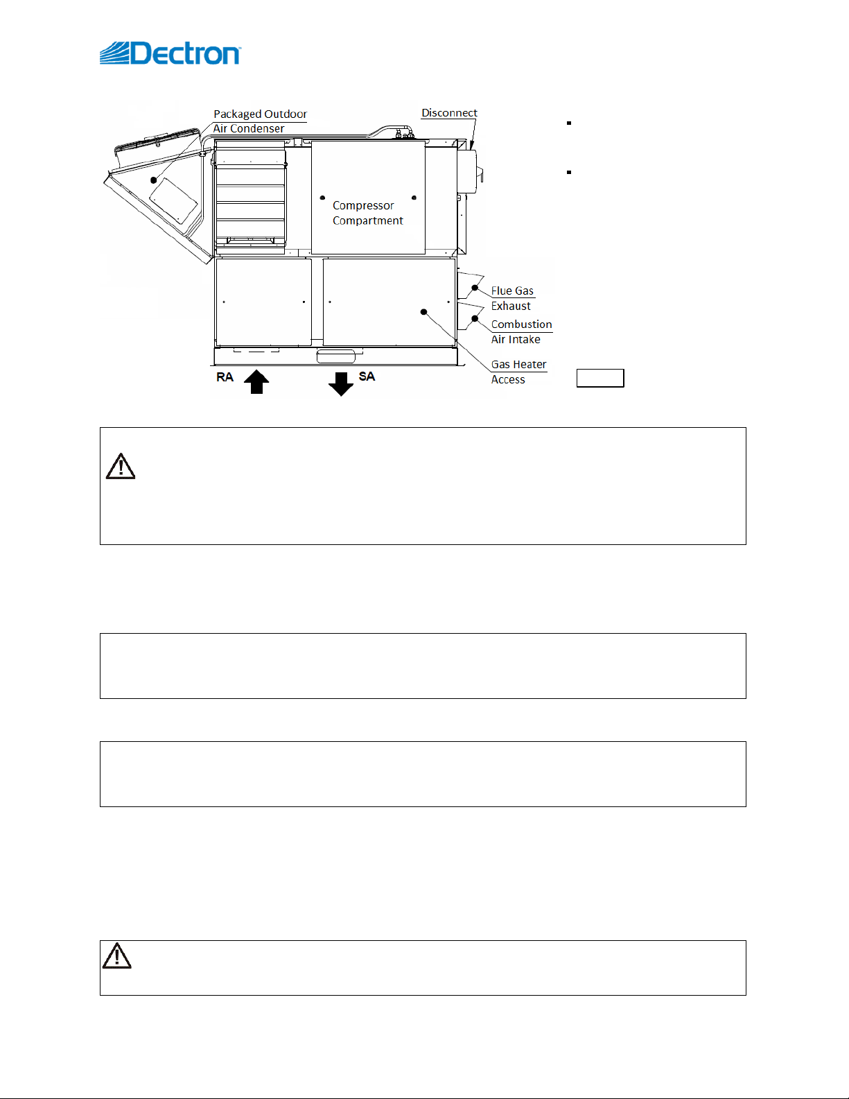
•Indoor or outdoor installation.
oPic. C.1. shows outdoor model, equipped with louvers (to protect air intake and discharge openings
from elements). Indoor model would have ducts connected to respective openings, no louvers would
be needed.
•Single-compressor dehumidifiers 8 to 16 tons’ capacity (apprx.), models DS040 to DS080 *.
oTwo-compressor dehumidifier option (see Dehumidifier Optional Arrangement below for details):
16 to 32 ton capacity (appx.) - models DS08D to DS15D;
8 to 20 ton capacity (apprx.) - models DS042 to DS102.
oLower compressor capacity (DS020 to DS035) is normally provided in different cabinet arrangement;
however, to accommodate additional ventilation and other options (like Purge, Heat Recovery etc. –
see below), not available with smaller cabinets, dehumidifier of smaller compressor capacity could be
provided in current cabinet also.
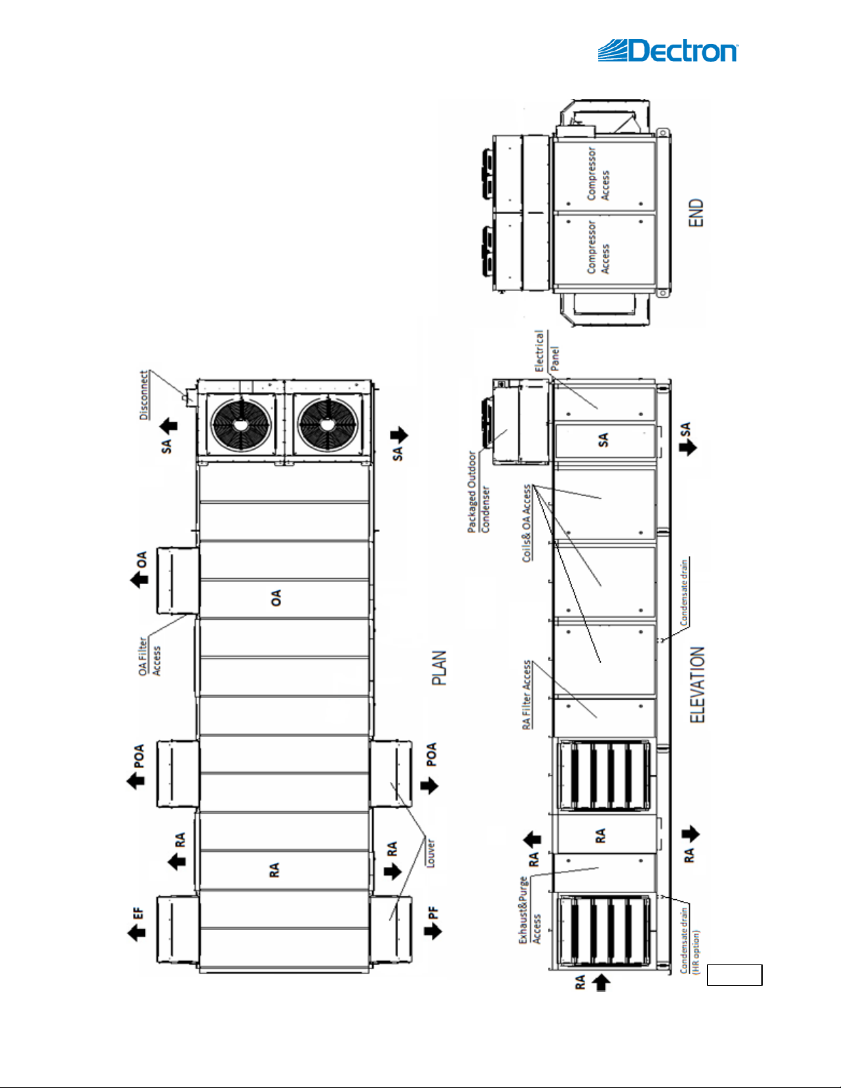
•Airflow/ductwork connection options * - as shown on Pic. C.1 and described below (some option locations
availability depends on the dehumidifier installation –indoor or outdoor):
oReturn Air (RA) ductwork connection - top, bottom, end, sides.
oSupply Air (SA) ductwork connection –top, bottom, sides.
oOptional Min Outdoor Air (OA) ductwork connection/termination –top, sides.
oOptional Min Exhaust Fan (EF) and Purge Fan (PF) ductwork connections/terminations –end, sides.
oOptional Purge Outdoor Air (POA) ductwork connection/termination - top, sides.
•Optional Pool Water Heating **.
•Optional Space Heating - hot water coil, electric or gas heater ***.
•Optional Heat Recovery (HR) circuit.
•Air Conditioning (AC)* –external water cooling, outdoor condenser or fluid cooler.
* All available options (tonnage, ductwork connections, AC options etc.) are shown. Refer to the submittal
and other relevant documentation for your dehumidifier’s options.
** The pool water heating option relies on compressor-created excess heat and is used as an additional
heating source. It does not eliminate the need for a main pool water heater.
*** For specific details on space heating (hot water, gas, electric) option, refer to the submittal and other
documentation:
•Gas-fired duct heater can be installed internally (fitted inside the dehumidifier at the factory) or provided for field
installation (to be fitted in the supply air ductwork).
•Electric heater or hot water coil, depending on capacity, model, size, etc., can be installed externally (mounted on the
top of SA opening or fitted in the supply air ductwork) or internally. Refer to your dehumidifier’s submittal
documentation.
Attention! Equipment Clearances and Dimensions!
CAUTION! For equipment proper operation, maintenance and service, respective clearances should be
maintained. Generally, 30” clearances to the equipment must be kept for the maintenance and service purposes.
For the specific required clearances information, as well as dehumidifier overall dimensions, distances to pipe
connections, duct connections etc., refer to the submittal documentation.

September 2020 9Dectron DS Series –Outdoor OMM
Dehumidifier External Systems Connection –BX Cab
Pic. C.1 shows provisions for external systems connections, including ductwork, electric power and control wires
and various piping connections.
Except for the condensate, all other piping systems are optional and may not be present in each
dehumidifier
•Condensate Drain Line –bottom, side (through the dehumidifier base).
•Air Conditioning (AC) Connection.
oPackaged AC option (outdoor dehumidifier with outdoor air condenser (OACC) incorporated with the
dehumidifier) does not require piping connection to external AC system or device.
Pic 1.C. shows packaged outdoor model with OACC mounted on the roof; alternatively, OACC
could be mounted at the end of the dehumidifier.
oRemote (“split”) AC option (indoor or outdoor dehumidifier, connected to external cooled
water/glycol system or remote fluid cooler or outdoor air condenser) –top (through the compressor
stand roof) connection.
Normally, the dehumidifier has only one AC option –air-cooled (requiring connection to the
outdoor air condenser) or water-cooled (requiring connection to the fluid cooler or other
external water-cooled system such as geothermal, cooling tower, etc.). Therefore, only one
of these options present with the actual dehumidifier.
•Pool Water Heating –bottom, side.
•Space heating (Hot Water connection) –bottom, side.
oSome connection location options for both, pool and space, heating pipe lines, are limited to indoor
installation only –refer to submittal documentation
•Space Heating (Gas Heater connection, gas line). If the dehumidifier is equipped with a gas heater (boiler, gas
furnace etc.) for space heating purposes, the gas line connection is to be brought to the gas heater directly.
•Electric Power and Control Connection. Electric power is normally brought to the dehumidifier disconnect
(see Pic. C.1). If dehumidifier is not equipped with it, power lines to be brought directly to the main electric
panel. Also, provisions are made to bring control and communication connections through the dehumidifier
roof at the compressor compartment
CAUTION! Current manual shows general/default connections’ location. For details regarding specific
dehumidifier’s connections (actual location, piping sizes and position dimensions, circuit type and flow direction
etc.), refer to the dehumidifier’s submittal documentation as well as dehumidifier’s labels and stickers.
NOTE. Dehumidifier MUST be equipped with a P-trap at the condensate connection for proper operation! If
dehumidifier is requested from the factory without P-trap, one MUST be installed on site prior to dehumidifier
being commissioned. Refer to the Installation Manual for details.
WARNING! Gas Line. The gas line must be installed in accordance with respective device documentation
(boiler, furnace, etc.) and local codes and regulations.

Dectron DS Series –Outdoor OMM 10 September 2020
Dehumidifier Optional Arrangement.
Two-Compressor Arrangement
Standard DS series dehumidifier has one compressor,
however two-compressor arrangement is available also. Note,
that all options and details, provided above, apply to both,
standard and two-compressor arrangement:
•Single Deck dehumidifier has same dimensions,
features and options as standard single-compressor
one, except for two compressor/refrigeration circuits
instead of one.
•“Double-Decker” dehumidifier is shown on Pic. C.3.
It is composed of two identical dehumidifiers, one
installed on top of another and controlled as a single
dehumidifier (each deck is equipped with one
compressor/refrigeration circuit).
Single and Two-Compressor Arrangement –Dehumidifier Model
Dehumidifier typical arrangement, total capacity, and number of compressors are reflected in its model (for
specific dehumidifier model refer to its Main Label –see Specific Data Info below), as illustrated in examples
below:
•DS040–single-deck single-compressor dehumidifier.
Two -compressor DS series dehumidifier:
•DS042- single-deck two-compressor dehumidifier (single deck equipped with two compressors);
•DS08D- double-deck two-compressor dehumidifier (composed of two identical dehumidifiers DS040).
Most often, “Double-Decker” comes as two horizontal dehumidifiers, one “stacked” on the top of another,
however it could also be composed of two dehumidifiers (horizontal OR vertical) installed side by side or
separately, still being controlled as one.
Pic. C.3

September 2020 11 Dectron DS Series –Outdoor OMM
Air Conditioning Option - Outdoor Air Condensers (OACC)
Packaged AC option (built-in outdoor air condenser) is a
standard one for this type of dehumidifier, however it could
be provided with remote AC option –remotely installed
Outdoor Air condenser or Fluid Cooler
Basic views of remote outdoor air condensers are shown on
Pic.C.4-C; standard combinations of the dehumidifier and
respective air conditioning option (based on their
capacities) are shown in Table C.1.
* Table C.1 shows standard dehumidifier and
condenser combination; depending on number of factors,
dehumidifier may have different condenser provided with it
- refer to the dehumidifier’s submittal documentation for
more details.
** Two-compressor dehumidifier would normally
have paired-up two outdoor condensers of respective size
(one per compressor).
For example, DS08D would have double-
condenser, composed of two NC-Z-1 (see
Pic.C.4, Fig.1).
Table C.1. Dehumidifier-AC Combination*
Dehumidifier –Outdoor Condenser**
Fig.#
DS020
NC-B
1
DS025 –DS040
NC-Z-1
2
DS050 –DS080
NC-Z-2
3
Attention!
Equipment Clearances and Dimensions!
Proper clearances should be maintained for
adequate airflow and heat rejection! Generally, up
to 36” side and 96” top clearances are required. For
more information on clearances as well as
equipment dimensions and other details, refer to
the submittal documentation.
Pic. C.4-C
Fig. 3.

Dectron DS Series –Outdoor OMM 12 September 2020
Air Conditioning Option - Fluid Coolers (OAFC).
Basic views of standard fluid coolers are shown on Pic.C.4-F (below); standard combinations of the dehumidifier
and respective air conditioning option (based on their capacities) are shown in Table C.1.
* Table C.1-F shows standard dehumidifier and cooler
combination; depending on number of factors, dehumidifier
may have different cooler provided with it - refer to the
dehumidifier’s submittal documentation for more details.
** The pump package is optional - the fluid cooler may
be provided without it.
Table C.1. Dehumidifier-AC Combination*
Dehumidifier –Fluid Cooler**
Fig.#
DS020 –DS035
NG-V-0
3
DS040 –DS060,
DS042 –DS062,
DS04D –NE06D
NG-V-11
4
DS070 –DS080,
DS072
DS07D –DS11D
NG-V-12
5
DS12D –DS15D
NG-V-22
6
Fig. 3
Fig. 4
Fig. 5
Fig. 6

September 2020 13 Dectron DS Series –Outdoor OMM
Equipment Specific Data
Specific information for individual dehumidifiers is provided in the following methods:
Main Label (Pic. C.5):the
manufacturer tag attached to the
front of the dehumidifier includes
the dehumidifier’s most critical data:
General data including:
oSerial number
oDehumidifier model
(nomenclature)
oDesign room conditions
(air temperature and
humidity)
Operational data, including:
oRefrigeration
(refrigerant type,
charge, etc.)
oElectrical/airflow
(dehumidifier voltage,
CFM, etc.)
oOther applicable data
(pool heating,
space/auxiliary heating
features, etc.)
Labels and Stickers: attached when
applicable to the exterior and
interior of the dehumidifier to show:
External systems connections
location/direction
(pool/space heating, cooling circuits, condensate)
Air filter locations, quantity, and size.
Additional Info (warning, caution stickers, etc.)
Wiring Diagrams: attached to the interior side of the
dehumidifier, depict dehumidifier control and power
wiring.
Remotely installed condenser or cooler would have its specific information provided in similar manner (labels etc.).
Note: The main label shown above is just an example.
Pic. C.5
Attention! Glycol Circuits.
Unless otherwise indicated, equipment fluid circuits (except for refrigeration and pool water circuits) such as heat
recovery loop, compressor glycol loop, boiler package, fluid cooler etc., are normally filled/to be filled with
water/glycol mixture; normally, rust inhibitor-infused food-grade propylene glycol is used.
Glycol mixture concentration is normally shown on Main Label –refer as needed.
Pic. C.4

Dectron DS Series –Outdoor OMM 14 September 2020
Layout and Components
The general layout and components location is the same for all dehumidifiers of current type, however some may
vary, based on the dehumidifier’s specific options –refer to submittal documentation. Pic. D.1-L and D.1-B below
shows all/most available options, some of which may not be present on your dehumidifier.
Dehumidifier Main Components - SLX
•Main Blower (1) is in the main blower compartment next to the Main Electric Panel (2) and Compressor
Compartment (3).
•Min Outdoor Air (OA) Opening (4) is equipped with a louver and, as an option, with a motorized damper and
filter(s). The Manual OA Damper (5) is usually used to set proper amount of outdoor air intake.
2
1
3
4
5
6
7
8
9
11
10
12
13
14
15
19
18
17
Pic. D.1-L
61
66
62
63
64
65

September 2020 15 Dectron DS Series –Outdoor OMM
•Exhaust Fan Assembly (6) (fan and motorized damper) is located on the dehumidifier’s return air side
opposite to the OA intake; Exhaust Air (EA) opening is equipped with a louver also.
oIf necessary, EA and OA louvers can be removed for shipping, service or maintenance; removing EA
louver also allows the Exhaust Fan assembly to be slid out from the dehumidifier.
•Refrigeration coils - Evaporator (7) and Reheat (internal condenser) (8) - are located directly downstream of
the Main Filter Rack (9).
oEvaporator Bypass Damper (10), is located next to the evaporator coil. It helps to control compressor
suction pressure by adjusting the amount of air, bypassing the evaporator.
•Space Heater (11) –hot water coil or electric heater (depending on the dehumidifier’s option) –It’s located
directly downstream of the Reheat coil.
oOptional Gas Heater Package (12), is normally installed under the dehumidifier. It includes gas heater
(61), gas heater electric and control panel (62) and provisions for combustion air intake (63) and flue
exhaust (64).
oPipe chase opening (65) in Compressor Compartment and Gas Heater Package floors allow for
external systems connections (pool and space heating, control etc.).
•Compressor (13), Receiver (14) and other components are located within the Compressor Compartment.
oIf the dehumidifier has the standard pool water heating option, the compressor circuit includes the
coaxial pool water heat exchanger (15) and refrigeration pool valve.
oFull Flow Pool Water Heat Exchanger (66) (optionally available with Gas Heater Package box only)
would be located within the package, replacing standard Coaxial Pool Water Heat Exchanger (15).
oIf the dehumidifier has the water-cooled air conditioning option (equipped with remote fluid cooler
or connected to external water-cooling source), the compressor circuit would also include the plate
heat exchanger, that would be located in compressor compartment.
•Main Electric Panel contains Main Control Board (17), Operator Panel (18) and other electrical components.
•Packaged Outdoor Air-Cooled Condenser (19) is normally mounted on the dehumidifier side.

Dectron DS Series –Outdoor OMM 16 September 2020
Dehumidifier Main Components - BX
•Main Blower (1) is in the main blower compartment behind or next to the Compressor Compartment (3) and
Main Electric Panel (2). Some models could be equipped with two main blowers.
•Min Outdoor Air (OA) Opening (4) is optionally equipped with a motorized damper and filter(s). The Manual
OA Damper (5) is usually used to set proper amount of outdoor air intake; in some cases, it could be equipped
with modulating actuator for automatic adjustment of outdoor air intake.
oOutdoor-installed dehumidifier would have louver(s) (76) installed at the OA opening.
•Optional Min Exhaust Fan (EF) Assembly (6) (fan and motorized damper) is located on the dehumidifier’s
return air side; Exhaust Air opening in outdoor-installed dehumidifier is equipped with louver(s) (76) also.
oMin Exhaust Fan Assembly is hinged and could be opened for better access to the fan electric box.
•Dehumidifier, equipped with Heat Recovery (HR) option, would have HR glycol coils (71), installed at the Min
Exhaust (EF) and Min Outdoor Air (OA) openings, and HR pump (72), installed in return air compartment.
oIf HR option is present, Min Exhaust Fan Assembly would normally be equipped with a filter rack.
•If dehumidifier is equipped with Purge option, additional Purge-exhaust fan (PF) (73) with motorized damper
would be installed on dehumidifier’s return air side, as well as additional (“Purge”) Outdoor Air (POA) (74)
opening(s), equipped with motorized dampers, would be located directly upstream of Main Filter Rack (9).
Motorized Return Air (RA) damper (75) would be located between return air side and POA opening(s).
oOutdoor- installed dehumidifier would have louvers (76) installed at the Purge-exhaust fan and Purge
Outdoor Air openings.
•Refrigeration coils - Evaporator (7) and Reheat (internal condenser) (8) - are located directly downstream of
the Main Filter Rack (9).
oEvaporator Bypass Damper (10) is located next to the evaporator coil. It helps to control compressor
suction pressure by adjusting the amount of air, bypassing the evaporator.
•Space heater (11a and 11b) location, if the dehumidifier is equipped with one, may vary:
oHot water coil or Electric heater (11a) is usually located directly downstream of the reheat coil;
oGas heater (11b) is usually located between main blower(s) and compressor compartment, however,
in some cases it could be installed externally.
oGas Boiler package (not shown), if provided, either installed remotely or mounted externally on the
dehumidifier end wall (return air side).
•Compressor (13), Receiver (14) and other components are located within the Compressor Compartment (3).
oIf the dehumidifier has the standard pool water heating option, the compressor circuit additionally
includes the coaxial pool water heat exchanger (15) and refrigeration pool water heating valve.
oIf the dehumidifier has the water-cooled air conditioning option (equipped with fluid cooler or
connected to external water-cooling source), the compressor circuit also includes the plate heat
exchanger (16). Some models may have refrigeration suction accumulator (13a).
oSingle-deck two-compressor dehumidifier would have two refrigeration circuits and two sets of
respective refrigeration devices (compressors, receivers etc.).
•Main Electric Panel contains Main Control Board (17), Operator Panel (18) and other electrical components.
Disconnect (77), if one is installed, usually located on the Compressor Compartment outer wall, opposite to
Main Electric Panel.
•Packaged Outdoor Air-Cooled Condenser (19), if dehumidifier is equipped with it, is normally mounted on the
roof or on the end wall (return air side).

September 2020 17 Dectron DS Series –Outdoor OMM
11b
2
1
3
5
4
7
8
9
11a
10
13
14
15
18
17
16
Pic. D.1-B
19
74
72
75
71
74
6
71
76
76
76
76
77

Dectron DS Series –Outdoor OMM 18 September 2020
Control System
The dehumidifier control system is composed of sensors, spread throughout the dehumidifier, Main Control
Board, Operator Panel and other electric components, located in the Main Electric Panel.
Temperature Sensors (Pic. D.2):
a) Temperature sensors (thermistors) are used to monitor
various temperatures (air, water, compressor, etc.);
b) Combo sensor is used to monitor air temperature and
humidity.
Compressor operation is monitored with pressure sensors (Pic. D.3):
c) Pressure Transducers (as main operational control and safety) and
d) Pressure Switches (fast-reacting backup safety).
Sensors and safeties approximate location is shown on Pic. D.4-L and D.4-B (see below).
•RA Combo Sensor (21) measures temperature and humidity of the pool room air (Return Air) entering the
dehumidifier. It is located at the return air ductwork connection to thedehumidifier.
•OA Temperature Sensor (22) measures outdoor air temperature; it’s located at the OA filter rack.
oAs an option, the combo sensor (instead of regular thermistor) can be installed at the OA intake to
measure both the temperature and humidity of the outdoor air.
•ET (EvapT) Temperature Sensor (23) measures the temperature of air leaving evaporator coil. It’s located
directly downstream of the evaporator.
•SA temperature sensor (24) measures the temperature of the air leaving the dehumidifier (supplied to the
premise). It must be located downstream of the space heater:
oIn some cases, where the space heater is external to dehumidifier, the sensor will be provided with
the dehumidifier to be field-mounted into the supply air ductwork downstream of the space heater.
•If the dehumidifier is equipped with the pool heating option, the Pool Water Temperature sensors (Pool In
(25) and Pool Out (26)) measure the entering and leaving pool water temperature. The sensors are located
directly at the respective connections of the coaxial pool water heat exchanger.
oAs an option, the pool water heat exchanger piping/manifold may have water flow switch also.
•The compressor’s discharge line (high pressure side) is equipped with Temperature and Pressure sensors set -
Discharge Temperature Sensor, High Pressure Transducer and High Pressure Switch (27) - to protect the
compressor and control its operation. A similar function is performed by Suction Temperature Sensor, Low
Pressure Transducer and Low Pressure Switch (28) located at compressor’s suction line (low pressure side).
•If dehumidifier is equipped with Heat Recovery option, it could also have Exhaust Air (EA) Temperature
Sensor (29), installed downstream of exhaust-side located heat recovery glycol coil.
•Main Electric Panel, apart from devices listed above (control board, OP, etc.) also contains Voltage Monitor;
some optional control sensors and devices such as an air pressure differential sensor, current sensor(s). It may
also be located in main electrical panel or in the dehumidifier in general.
b
a
c
d
Pic.D.3
Pic. D.2

September 2020 19 Dectron DS Series –Outdoor OMM
27
21
23
24
22
28
25
26
Pic. D.4- L
This manual suits for next models
16
Table of contents
Other Dectron Dehumidifier manuals
Popular Dehumidifier manuals by other brands

Oasis
Oasis D260 ECO Owner's manual and warranty

Frigidaire
Frigidaire FAD504DWD Use and care

Ecoair
Ecoair DROID user manual

SMC Networks
SMC Networks IDG1-C06 Series Operation manual

Desert Aire
Desert Aire SelectAire Plus SP Series Installation and operation manual

Seaira Global
Seaira Global WatchDog 900c Installation and operation manual