Dedal-NV Tracker-T2.380 User manual

MOSCOW, RUSSIA, 2019
THERMAL VISION
BINOCULARS
Operation Manual
Tracker-T2.380
Tracker-T4.642

Tracker-T2.380/ Tracker-T4.642. Operation Manual
2
Table of Contents
1 DEVICE APPEARANCE................................................................................................ 3
2 DEVICE DESIGNATION AND KEY FEATURES.................................................... 4
3 TECHNICAL PARAMETERS....................................................................................... 5
4 DELIVERY SET ............................................................................................................... 7
5 PREPARATION FOR USE............................................................................................ 8
5.1 Batteries Installation .......................................................................................... 8
5.2 Start-up and Shutdown...................................................................................... 8
6 DEVICE DESIGN AND OPERATION ........................................................................ 8
6.1 Operational Menu ................................................................................................ 9
6.2 Thermal Module Mode Menu ........................................................................10
6.3 Colour Scheme Menu ........................................................................................10
6.4 Rangefinder ..........................................................................................................11
6.5 Service Menu........................................................................................................12
6.5.1 Calibration....................................................................................................12
6.5.2 Dead Pixels Removal................................................................................ 12
6.5.3 Language Selection Menu....................................................................... 13
6.5.4 Information.................................................................................................. 13
7 MARKING ...................................................................................................................... 13
8 TROUBLESHOOTING ................................................................................................ 14
9 TECHNICAL SERVICE ............................................................................................... 15
10 TRANSPORTATION AND STORAGE ................................................................. 15
11 UTILIZATION ............................................................................................................ 15
A T T E N T I O N !
Do not aim the working binoculars at intensive heat sources such as the Sun, working welding
equipment, fire, etc. This may damage the binoculars partially or completely!
Remove batteries from the device if it is not in use for a long period!
Non-observance of the rules of use and storage of the device may void the manufacturer's warranty.
Tracker-T2.380/Tracker-T4.642. Operation Manual
3
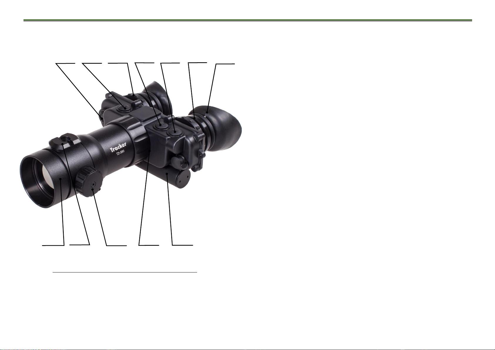
1 DEVICE APPEARANCE
Figure 1. Device appearance and controls
1 –POWER button (On/Off)
2 –INVERSION/MENU/ОК button
3 –BRIGHTNESS/(1×/2×)* button
4 –BRIGHTNESS + button
5 –Body of the device
6 –Objective lens
7 –Eyepieces
8 –Dioptre adjustment and interpupillary distance adjustment
mechanism
9 –Manual focusing adjustment mechanism
10 –Battery compartment
11 –Eyepiece rubbers
12 –Fixation rail for external rangefinder
* Tracker-Т4.642 model only
1
3
5
8
2
4
11
6
12
10
7
9

Tracker-T2.380/Tracker-T4.642. Operation Manual
4
The present operation manual describes functioning and
operational rules of the Tracker-T2.380/Tracker-T4.642
thermal vision binoculars (further: Device).
2 DEVICE DESIGNATION AND KEY FEATURES
The Device is designated for terrain surveillance under any
illumination (day, night, dusk and complete darkness) and any
weather conditions (rain, fog, snowfall, etc.).
The operational principle of the Device is based on the
transformation of the infrared emission from subjects and
objects into a visible image that is easy for human perception.
Key Features:
Unique dynamic contrast system, which provides the
most informative thermal images of the observed objects;
Automatic brightness and contrast correction system,
which does not require any manual adjustments in changing
environmental conditions;
Automatic calibration system of the shutterless sensor
and, as a sequence, the image is noise free and does not
“freeze”;
Detail contrasting system for both target and
background regardless of difference between their
temperatures;
High frame refresh rate and elimination of image
blurring effect;
Several colour schemes with various types of target
emphasising;
Fast start time (not more than 3 seconds);
Dead pixels removal system;
High quality aspheric germanium lens;
High image quality across the full field of view;
Low power consumption;
Hermetically sealed, nitrogen filled;
Compact / lightweight.

Tracker-T2.380/Tracker-T4.642. Operation Manual
5
3 TECHNICAL PARAMETERS
Table 1*
Parameter, unit of measurement
Value
Tracker-T2.380
Tracker-T4.642
SENSOR
Frequency, Hz
50
25
Resolution, pixels
384x288
640x480
Detector pitch, microns
17
Type
Uncooled bolometer array (FPA)
Sensitivity wavelength range, microns
from 8 to 14
Thermal sensitivity (NETD), mK
<70
Calibration principle
Programmatic (shutterless)
OBJECTIVE LENS
Focal length
50 mm F/1.2
100 mm F/1.6
Manual focusing range
from 5 m to
from 20 m to
Optical magnification
3.4
3.5 or 7
Field of view, o(horizontal ×vertical)
7.4×5.6
6.2×4.7
DISPLAY
Array type
AMOLED
Resolution, pixels
800×600

Tracker-T2.380/Tracker-T4.642. Operation Manual
6
POWER SOURCE
Battery type
CR123
Number of batteries
2
Voltage, VDC
6 (3.5..7.4)
PHYSICAL CHARACTERISTICS
Dimensions, mm (L×W×H), not more
200×150×77
240×150×77
Weight, kilograms, not more
0.64
0.8
ENVIRONMENTAL CHARACTERISTICS
Operating temperature, oC
From -40 to +50
Humidity at 25 oC, %
from 0 to 98
Time of continuous operation under T=20 oC, hours
4
* Technical parameters of the Device may be improved without prior notice of the customer.
This Device employs a system of automatic calibration of the shutterless sensor, which permanently optimizes Device
performance. This option together with the dynamic contrast system delivers optimal image without any manual adjustments.
N O T E :
As a consequence of the above mentioned systems functioning, some visual noise in the form of vertical stripes and grain
effects may be visible on the screen under certain conditions. These insignificant disturbances will practically vanish from
sight when a thermally contrast target appears in the field of view.

Tracker-T2.380/Tracker-T4.642. Operation Manual
7
4 DELIVERY SET
STANDARD DELIVERY SET
1
Thermal vision binoculars Tracker-T2.380 (Tracker-T4.642)
1 pc.
2
Batteries CR123*
2 pcs.
3
Cleaning optical cloths set*
1 pc.
4
Protective bag
1 pc.
5
Operation manual
1 pc.
6
Warranty card
1 pc.
AUXILIARY DELIVERY SET (upon request under a special order)
7
“Cat’s eye” eyepiece
2 pcs.
8
External rangefinder LE-032
1 pc.
9
Optics cleaning liquid*
1 pc.
10
Hard case
1 pc.
* Not covered by warranty
Technical parameters and device delivery set may be changed by the manufacturer without prior notice of the customer

Tracker-T2.380/Tracker-T4.642. Operation Manual
8
5 PREPARATION FOR USE
5.1 Batteries Installation
The Device is powered by two batteries CR123. Ensure that
the batteries are inserted into the Device in accordance with the
labelling inside the battery compartment, and they are
adequately charged.
To change the batteries, remove the screw (10) (Fig.1) of
the battery compartment cap and replace the old batteries with
new ones observing their polarity.
5.2 Start-up and Shutdown
Turn on the Device by pressing and holding button (1)
(Fig. 1) for more than two seconds until the image appears on
the screen.
Two-three seconds later the observed image appears in
the field of view.
Turn off the Device by pressing and holding button (1)
(Fig. 1) for more than two seconds after use.
6 DEVICE DESIGN AND OPERATION
The Device has the built-in operational menu with the
structure as shown in Fig. 3.
Focusing of the objective lens is adjusted by rotating the
knob (9) (Fig. 1) to achieve optimal sharpness of the observed
objects.
To adjust the dioptre setting, rotate the eyepieces (8) as
shown in Fig. 2.
The interpupillary distance is adjusted by moving the
eyepieces (8) together and apart for optimal vision through
both eyes.
Figure 2. Dioptre and Interpupillary Distance Adjustment

Tracker-T2.380/Tracker-T4.642. Operation Manual
9
N O T E !
Due to different discharge curves of different battery brands,
the battery discharge indicator may show less accurate
information.
In the Tracker-T2.380 model, you can change the screen
brightness by pressing buttons (3) and (4) in observation mode.
In the Tracker-T4.642 model, you can change the screen
brightness or digital zoom (1x / 2x) by pressing buttons (3) and
(4) in observation mode depending on which button was
pressed first.
Brightness adjustment and digital zoom indicators appear
in the top centre of the screen.
Battery discharge indicator is shown in the top of the
screen and measured in percent.
6.1 Operational Menu
Enter the main menu by pressing button (2) (Fig. 1) for
more than two seconds. The appearance of the main
(operational) menu is shown in Figure 3.
<EXIT
THERMAL VISION MODE
COLOUR SCHEME
RANGEFINDER
SERVICE
QUICK MENU
Figure 3 –Operational Menu
The operational menu is shown in the centre of the screen.
Use buttons (3) and (4) for navigation through the menus.
Press button (2) to confirm the selected option.
Select the line EXIT to leave the operational menu
Select the line BACK to leave the current submenu and
move one level up.
Tracker-T2.380/Tracker-T4.642. Operation Manual
10
THERMO MODE
COLOR SCHEME
RANGEFINDER
CALIBRATION
SERVICE
PIXEL MACKING
LANG. SELECT
INFO
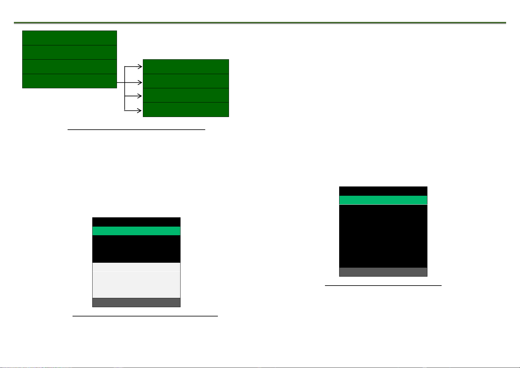
Figure 4. Operational Menu Structure
6.2 Thermal Module Mode Menu
You can choose one of four pre-set automatic modes for the
thermal module (Fig. 11). These modes have different factory pre-
set levels of contrast and noise reduction. Using button (3) and (4),
select one for the best image quality.
<BACK
•MODE 1
MODE 2
MODE 3
MODE 4
THERMO MODE
Figure 5 –Thermal Module Mode Menu
6.3 Colour Scheme Menu
The Colour Scheme menu applies one of eight pre-
programmed algorithms of image colour processing depending
on the temperature of the observed subjects and objects (see
Fig. 6).
If you set the colour scheme, it will be added to two inverse
black and white options as the third user-defined scheme, which
can be toggled by fast pressing of button (2) in the observation
mode.
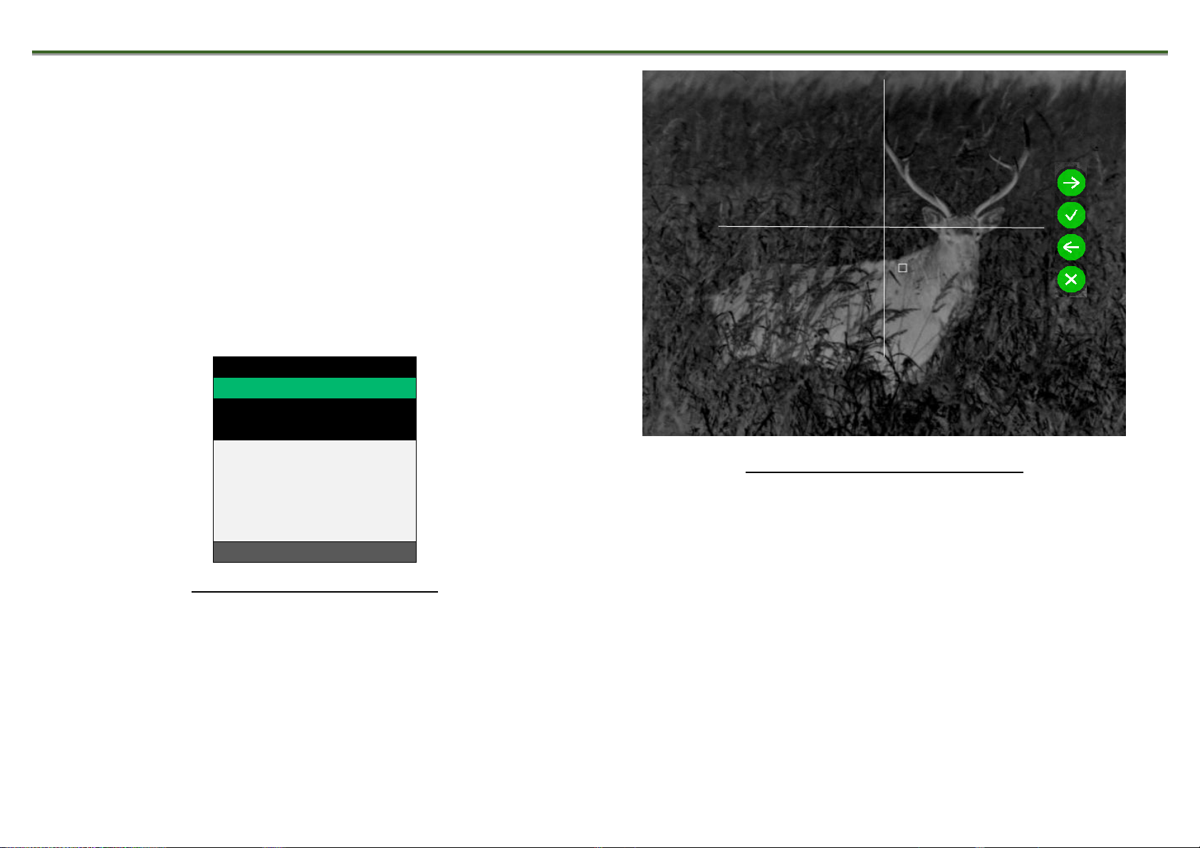
<BACK
•BLACK-WHITE
RED-GREEN
RED-BLUE
SPECTRUM-1
SPECTRUM-2
SPECTRUM-3
BLACK-YELLOW
BRW
COLOR SCHEME
Figure 6 –Colour Scheme Menu
Tracker-T2.380/Tracker-T4.642. Operation Manual
11
6.4 Rangefinder
The fixation rail (12) can be used for attaching of an
external rangefinder (for example, LE-032, which is included in
the auxiliary delivery set).
You can switch on a special crosshair mark on the screen In
the RANGEFINDER section of the menu (see Fig. 8). This
crosshair indicates the rangefinder coverage zone.
The rangefinder mark size is 2×2 mil.
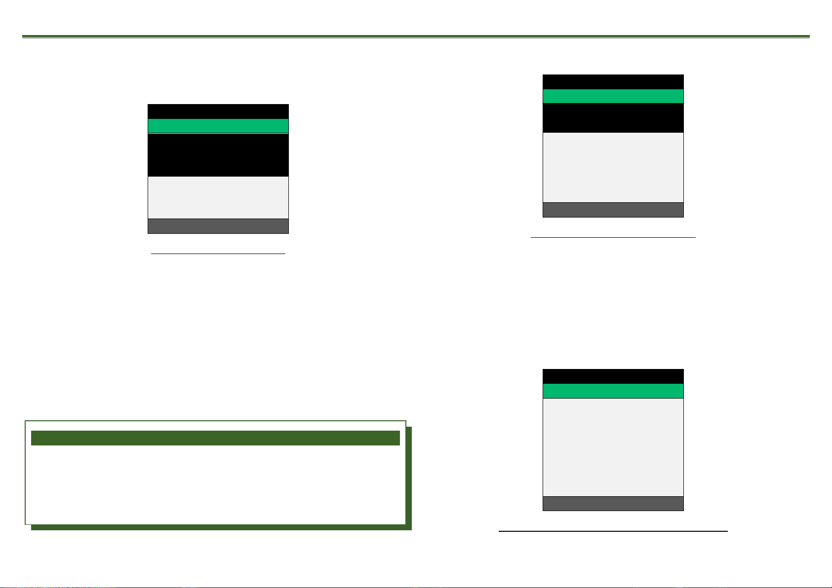
<BACK
•OFF
ON
ALIGN
RANGEFINDER
Figure 7 –Rangefinder menu
Figure 8 –Rangefinder crosshair
The ZEROING menu option allows adjusting of the
rangefinder mark position with buttons (3) and (4).
Tracker-T2.380/Tracker-T4.642. Operation Manual
12
A T T E N T I O N !
During calibration, the objective lens must be closed. If you
perform calibration with the open objective lens cap, you
will get a negative darkened image on the screen.
6.5 Service Menu
The Service menu is shown in Fig. 9.
<BACK
CALIBRATION
PIXEL MASKING
LANG. SELECT
INFO
SERVICE
Figure 9. Service Menu
6.5.1 Calibration
This section allows performing manual calibration and
setting the calibration mode (Fig. 10). To perform forced
calibration, close the objective lens cap, enter the Calibration
menu, select the NOW line, and press button (2). Calibration will
take few seconds.
<BACK
•AUTO
EXECUTE
STARTUP
CALIBRATION
Figure 10. Calibration Menu
6.5.2 Dead Pixels Removal
If you notice defective pixels on the screen, you can remove
them from the menu. To do this, enter the corresponding menu
section, select the line EXECUTE and press button (2).
<BACK
EXECUTE
PIXEL MASKING
Figure 11 –Dead Pixels Removal Menu

Tracker-T2.380/Tracker-T4.642. Operation Manual
13
A T T E N T I O N !
During dead pixels removal procedure, the objective lens
must be closed. If you perform dead pixels removal with the
open objective lens cap, you will get more dead pixels
instead of less.
6.5.3 Language Selection Menu
In this section, you can select one of the several languages.
<BACK
•English
Magyar
Deutsch
Polski
LANG. SELECT
Figure 12. Language Selection Menu
*Attention! The exact set of languages depends on the
country of destination and may be changed without prior notice.
6.5.4 Information
In this section, you can see the Device model name and
software release code (Fig. 14).
MANUFACTURER:
JSC DEDAL-NV
MODEL:
Tracker 380.T2
SOFTWARE VERSION
4.3t-006
CORE SN:
11111 v12
INFO
Figure 14 –Information Screen
7 MARKING
The Device marking contains its model name and serial
number.

Tracker-T2.380/Tracker-T4.642. Operation Manual
14
8 TROUBLESHOOTING
Table 2
Malfunction
description
Troubleshooting solution
The Device does not work
Check whether the batteries are installed properly. Check the charge of the batteries. Replace them
if they are weak.
The target does not appear
in focus
Rotate the eyepieces (7) (Fig.1) and adjust the interpupillary distance (see Fig. 2) until you get a
clear image of the screen for each eye. Then achieve the best-focused image of the object by rotating
the objective lens knob (10). If the image cannot be focused as described in this manual, clean the
lenses. They could be moisturized or dusty.
Condensation accumulates
on the parts
It is recommended to use periodically a special protective anti-misting liquid in order to avoid
misting of the objective lens in cold conditions. This liquid is included in the auxiliary delivery set.
Dots on the screen
Production technology of the display allows a small amount of dark and bright dots in the image.
These dots may also appear after some usage. Most of the appeared dots can be removed by using
the function DEAD PIXELS REMOVAL (see 6.5.2).
A T T E N T I O N !
While the Device is operating, presence of one or several darker or lighter segments (spots, stripes) in the field of view is
allowed. Mostly often, these segments appear if there is a large temperature gradient between the place, where the observer
is located, and the outside environment. For example, this may happen when you observe the terrain from a warm room
through an open window. In some cases, these segments can be removed by using the CALIBRATION function.

Tracker-T2.380/Tracker-T4.642. Operation Manual
15
9 TECHNICAL SERVICE
Technical service comprises external appearance
inspection and supplied delivery set completeness check.
The external appearance of the Device must correlate to the
technical documentation. Dents on external surfaces are not
allowed. All fixtures must be tightened. Rotation and
spontaneous unscrewing of parts during operation are not
allowed. All moving components of the Device must be moved
smoothly without backlash and jamming.
It is recommended to periodically clean the external optical
parts with the supplied cloth to protect them from moisture and
dust.
10 TRANSPORTATION AND STORAGE
Store the Device in the supplied protective bag or a hard
case with the protective objective lens cap on. Store the Device
at temperatures from than 10oC to 35oC with relative humidity
not exceeding 85%. Remove the batteries from the Device
during extended periods of non-operation to avoid batteries
leakage.
Transportation of the Device in the protective bag or hard
case can be performed by any transport to any distance,
including transportation by air in a hermetically sealed
compartment.
Preserve the Device from impacts, direct sunlight, rain,
snow, and dust.
11 UTILIZATION
The Device does not present a danger to humans or nature.
Only metal alloy parts of the Device are subjects for recycling. If
necessary, request the list of the alloys content from the
manufacturer.

OPERATION MANUAL
Tracker-T2.380
Tracker-T4.642
Ver. 4.3 t
DEDAL-NV
Russia, 107076,
18 Stromynka St., Moscow
Tel: +7(495) 589-31-01, +7(495) 617-05-96, 97
Fax: +7(495) 961-27-49
http://www.dedalnvoptics.com
e-mail: info@dedalnvoptics.com
This manual suits for next models
1
Table of contents


