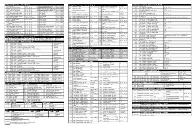
ALTERNATE CONFIGURATION (PAGE 20)
2001 Default Configuration On (1), Off (0)
202
Delayed Over Current Alarm
Action 0 (Action)
Under Voltage Shutdown Enable
Under Voltage Shutdown Trip
Overload Protection Enable
Under Voltage Warning Enable
Overload Protection Action
Under Voltage Warning Trip
Overload Protection Trip Delay
Over Voltage Warning Enable
Over Voltage Warning Return
Over Voltage Warning Trip
Mains Under Voltage Enable
2013
Enable On (1), Off (0)
2040 Mains Under Voltage Trip 0 V
Under Frequency Shutdown Trip
Mains Under Voltage Return
2015
Enable On (1), Off (0)
2042 Mains Over Voltage Enable On (1), Off (0)
Under Frequency Warning Trip
Mains Over Voltage Return
Mains Under Frequency Enable
Over Frequency Warning Enable
Mains Under Frequency Trip
Over Frequency Warning Return
Over Frequency Warning Trip
Mains Over Frequency Enable
2022
Enable On (1), Off (0)
2049 Mains Over Frequency Return 0.0 Hz
Over Frequency Shutdown Trip
Mains Over Frequency Trip
Under Speed Shutdown Enable
Under Speed Shutdown Trip
Delayed Over Current Alarm
Battery Over Volts Warning
4 Battery Under Volts Warning 37
Shutdown 70 RESERVED
5 RESERVED
3
Shutdown 71 RESERVED
Over Current Immediate Warning
Delayed Over Current Trip Alarm
9 RESERVED
42
Shutdown 75 Fuel Sender Low Pre-Alarm
Charge Alternator Shutdown
Charge Alternator Warning
Air Filter Maintenance Output
Fuel Filter Maintenance Output
Preheat During Preheat Timer
Preheat Until End Of Crank
24 Digital Input C 57
Preheat Until End Of Safety
Timer 90 Analogue Input C (Digital)
Preheat Until End Of Warming
2 RESERVED 61
Circuit 94 MPU Open Circuit
Alternative Configuration
7
Switch 16 Remote Start On Load 25 Maintenance Reset Air
TYPICAL WIRING DIAGRAM
053-156 Issue 1
DEEP SEA ELECTRONICS PLC
DSE4610 & DSE4620 Installation Instructions
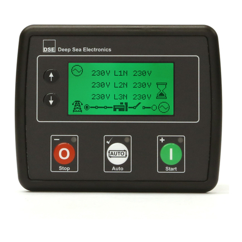
EDITING A PARAMETER
• Press the (
-
) and ()
buttons together to enter the editor
mode.
• Press the (up) or (down) navigation buttons to cycle through the
front panel editor in increments of 100.
• Press the (
+
) or (
-
) navigation buttons to cycle through the front
panel editor in increments of 1.
• When viewing the parameter to be edited, press the()
button and the value
begins to flash.
• Press the (
+
) or (
-
) navigation buttons to adjust the value to the
required setting.
• Press the ()
button the save the current value, the value ceases
flashing.
• Press and hold the ()
button to save and exit the editor, the
configuration icon is removed from the display.
NOTE: Pressing and holding the (
+
) or (
-
) buttons will
give auto-repeat functionality. Values can be changed quickly by holding
the navigation buttons for a prolonged period of time.
(5.5” x 4.4” x 1.7”)
(4.6” x 3.6”)
(AWG 24 to AWG 10)
NOTE: Terminals 8, 9, 25, 26, 2 & 28 are not fitted to DSE4610
Tel: +44 (0)1723 90099
Fax: +44 (0)1723 93303
Email: sales@deepseaplc.com
Web: www.deepseaplc.com
Tel: +1 ( 15) 316- 706
Fax: +1 ( 15) 316- 70
Email: sales@deepseausa.com
Web: www.deepseausa.com
NOTE: A larger version of the typical wiring diagram is included in
the products operator manual. Refer to DSE Publication:
057-200 DSE4610 & DSE4620 Operators Manual
REQUIREMENTS FOR UL CERTIFICATION
Screw Terminal Tightening Torque
4.5 lb-in (0.5 Nm)
Terminals suitable for connection of conductor size 12 AWG – 26 AWG (0.5 mm² to 2.0 mm²).
• Conductor protection must be provided in accordance with NFPA 70, Article 240
• Low voltage circuits (35 volts or less) must be supplied from the engine starting battery or an isolated secondary circuit.
• The communication, sensor, and/or battery derived circuit conductors shall be separated and secured to maintain at least ¼” (6 mm) separation from the generator and mains connected circuit
conductors unless all conductors are rated 600 volts or greater.
Must be connected through UL Listed or Recognized isolating current transformers with the secondary rating of 5 A max.
Must be connected to communication circuits of UL Listed equipment
0.5 A
Suitable for use in type 1 Enclosure Type rating with surrounding air temperature -22 ºF to +15 ºF (-30 ºC to +70 ºC)
• Suitable for pollution degree 3 environments when voltage sensing inputs do not exceed 300 V. When used to monitor voltages over 300 V device to be install in an unventilated or filtered ventilation
enclosure to maintain a pollution degree 2 environment.
-22 ºF to +15 ºF (-30 ºC to +70 ºC)
-40 ºF to +176 ºF (-40 ºC to + 0 ºC)
4610/4620


