Chino DB600 Series User manual

INST.No.INE-868G [DB600] General Instruction Manual
Digital Indicating
Controller
DB600
【General】 PID control
Instruction Manual
Thank you for purchasing Digital Indicating Controller [DB 600 series]. Understand the instrument properly
and read this instruction manual beforehand in order to avoid any troubles.
- For the persons doing instrumentation, installation and sales -
Be sure to handover this instruction manual to the persons using the
instrument.
- For the users of the instrument -
Preserve this instruction manual until you scrap the instrument and
write down the setting details.

I

INST.No.INE-868G [DB600] General Instruction Manual
- 1 -
Introduction
Thank you for purchasing Digital Indicating Controller [DB 600 series].
Understand the instrument properly and read this instruction manual beforehand in order to avoid any
troubles.
For specification regarding communications interfaces, read [Communications interfaces instruction
manual] along with this manual.
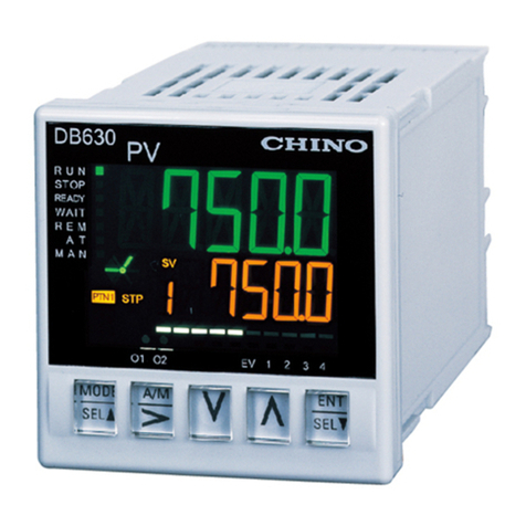
About DB600
(1) DB600 (with programming function) is a digital programming controller which is able to store
maximum 4 patterns by 12 steps programming operations.
(2) SV, PID, event, output limiter, and guaranty soak (with program function) are able to be registered at
8 types of group parameters.
(3) High accuracy of measured accuracy ± 0.1 % and control interval 0.1 sec.
(4) Display measured value (PV)/setting value (SV) and analog bar of output value by high view
angle/brightness provided by LCD.
Product warranty scope
This instrument is warranted for one year from the date of delivery. If it is damaged during the
warranty period, when used normally based on the cautions in the instruction manual, labels, and
markings attached to the instrument, etc., it will be repaired without any charge (only in Japan). In
the case, we are sorry to trouble you, but please contact your dealer or nearest our sales office.
However, in cases of the followings, it will be repaired at your expense even during warranty period.
1. Failure or damage caused by improper use or connection, or invalid repair or modification.
2. Failure or damage caused by fire, earthquake, wind or flood, thunderbolt, or other extraordinary
natural phenomena, or pollution, salt, harmful gas, abnormal voltage, or use of unspecified
power.
3. Replacement of parts or accessories that have reached the end of their life.
4. In the case of failure that is caused by product other than CHINO's.
Furthermore, the term ‘warranty’ in this sense covers only a CHINO’s product itself. Therefore, we
are not responsible for compensation for whatever the damage that is triggered by failure of our
product.
Notice
1. No part of this manual can be reproduced or copied in any form without permission.
2. The contents of this manual may be altered without prior notice.
3. This manual has been documented by making assurance doubly sure. However, if any question
arises or if any error, an omission, or other deficiencies are found, please contact your nearest
our sales office.
4. CHINO is not responsible for any operation results of this instrument.
Other described company names and product names are trademarks and registered products of
the respective companies.
Please note that the marks "TM "and "®"are omitted throughout this manual.

INST.No.INE-868G [DB600] General Instruction Manual
- 2 -
Table of contents
Introduction....................................................... 1
Table of contents .............................................. 2
1Before use ........................................ 4
1-1 For safe use of the product...................... 4
1-1-1
Preconditions for use.............................. 4
1-1-2
Cautions for long term usage.................. 4
1-1-3
Symbol mark........................................... 5
1-1-4
Request for opening and handling.......... 5
1-1-5
Important ................................................ 6
1-2 Before use ............................................... 7
1-2-1
Confirm the accessories ......................... 7
1-2-2
Confirm the exterior ................................ 7
1-2-3
Confirm the model code ......................... 7
1-2-4
Model code list........................................ 8
1-3 Mounting condition................................. 13
1-3-1
Environment ......................................... 13
1-3-2
Surrounding condition........................... 13
1-3-3
Mounting conditions.............................. 13
1-3-4
Others................................................... 13
2Mounting and wiring....................... 14
2-1 External dimensions .............................. 14
2-1-1
Unit dimensions .................................... 14
2-1-2
Panel cutout and mounting dimensions 15
2-2 Mounting ................................................ 17
2-2-1
Panel mounting..................................... 17
2-2-2
Waterproof specifications ..................... 18
2-3 Wiring..................................................... 19
2-3-1
Precautions during wiring ..................... 19
2-3-2
Insulation block..................................... 20
2-3-3
Terminal number and functionality ........ 20
2-3-4
Basics of wiring..................................... 30
2-3-5
Example of wiring ................................. 32
2-4 Trial operation ........................................ 35
2-4-1
Confirmations before operation ............ 35
2-4-2
Procedure of trial operation .................. 36
2-5 Initial settings ......................................... 37
2-5-1
Initialize parameter ............................... 38
3Names of various parts.................. 39
3-1 Entire overview ...................................... 39
3-2 Name and function of display ................ 40
3-3 Character display................................... 42
3-4 Name and function of key ...................... 42
4Operation ........................................ 43
4-1 Cautions on power ON .......................... 43
4-2 Operation on power ON........................ 43
4-3 Constant value operation....................... 44
4-3-1
Setting overview ................................... 44
4-3-2
Setting item screen and function .......... 44
4-3-3
RUN/READY status.............................. 51
4-4 Program operation ................................. 52
4-4-1
Setting overview ................................... 52
4-4-2
Setting item screen and function .......... 52
4-4-3
Program operation method................... 60
4-5 AUTO
/
MANUAL output operation ............ 61
4-6 Cautions for operation ........................... 62
4-6-1
Setting/changing a parameter during
operation............................................... 62
4-6-2
Cautions for SV slope operation ........... 62
5Setting operations ......................... 63
5-1 Basics of setting......................................63
5-1-1
Setting item screen display ...................63
5-1-2
Basic operations on the setting screen .64
5-1-3
How to operate parameter setting.........65
5-1-4
Precautions for setting ..........................67
5-2 MODE0 [Executing parameter]...............68
5-2-1
Setting overview ...................................68
5-2-2
Setting item screen and function...........68
5-2-3
Changing an executing step .................71
5-2-4
Output limiter ........................................71
5-3 MODE1 [Constant value operation
parameter] ..............................................72
5-3-1
Setting overview ...................................72
5-3-2
Setting item screen and function...........72
5-3-3
SV rate of change .................................73
5-3-4
Constant value operation PV start ........73
5-4 MODE2 [Program parameter].................74
5-4-1
Setting overview ...................................74
5-4-2
Setting item screen and function...........74
5-4-3
Program pattern setting ........................80
5-4-4
Selecting the start method for program
operation...............................................82
5-4-5
Execution No. selection for program
operation...............................................82
5-4-6
Program pattern link (connection).........82
5-4-7
Output at program end (output 1 and 2 at
END).....................................................82
5-5 MODE3 [Group parameter] ....................83
5-5-1
Setting overview ...................................83
5-5-2
Setting item screen and function...........83
5-5-3
Setting 8 parameters for each group ....85
5-6 MODE4 [Event parameter] .....................86
5-6-1
Setting overview ...................................86
5-6-2
Setting item screen and function...........86
5-6-3
Event mode...........................................88
5-6-4
Event extension function.......................88
5-6-5
Event deadband....................................89
5-6-6
Event output phase...............................89
5-7 MODE5 [Input parameter] ......................90
5-7-1
Setting overview ...................................90
5-7-2
Setting item screen and function...........90
5-7-3
Input type, measuring range, and linear
scale .....................................................92
5-7-4
Input correction .....................................93
5-7-5
SV limiter ..............................................93
5-8 MODE6 [Control parameter]...................94
5-8-1
Setting overview ...................................94
5-8-2
Setting item screen and function...........94
5-8-3
Pulse cycle............................................97
5-8-4
Feedback input .....................................98
5-8-5
PID deadband/output deadband ...........98
5-8-6
Control action........................................98
5-8-7
Output variation limiter ..........................99
5-8-8
Fixed output setting ..............................99
5-8-9
Control algorithm ..................................99
5-9 MODE7 [Output 2 parameter]...............100
5-9-1
Setting overview .................................100
5-9-2
Setting item screen and function.........100
5-9-3
Output 2 control system......................103
5-10 MODEa [Communication parameter] ...104
5-10-1
Setting overview .................................104
5-10-2
Setting item screen and function.........104

INST.No.INE-868G [DB600] General Instruction Manual
- 3 -
5-11 MODEb [Transmission output parameter] .
..................................................... 106
5-11-1
Setting overview ................................. 106
5-11-2
Setting item screen and function ........ 106
5-11-3
Transmission scale ............................. 107
5-12 MODEc [Remote input parameter] ...... 108
5-12-1
Setting overview ................................. 108
5-12-2
Setting item screen and function ........ 108
5-12-3
Remote/local switch............................ 109
5-12-4
Correcting remote SV input .................111
5-12-5
Tracking...............................................111
5-12-6
Remote SV scale.................................111
5-13 MODEd [External input parameter] ......112
5-13-1
Setting overview ................................. 112
5-13-2
Setting item screen and function ........ 112
5-14 MODEt [System parameter]..................114
5-14-1
Setting overview ................................. 114
5-14-2
Setting item screen and function ........ 114
6Detailed description for main function
.................................................... 118
6-1 Measuring range...................................118
6-2 Linear scale ..........................................119
6-3 Alarm event type.................................. 120
6-4 Status event......................................... 125
6-5 Auto tuning........................................... 126
6-6 PID control ........................................... 127
6-6-1
P control ............................................. 127
6-6-2
I control............................................... 127
6-6-3
D control ............................................. 128
6-7 Actuator adjustment for ON-OFF servo
output type ........................................... 129
6-7-1
Auto adjustment.................................. 129
6-7-2
Manual adjustment ............................. 130
6-8 2 Outputs ............................................. 131
6-8-1
PID control calculation........................ 131
6-8-2
Split control calculation....................... 132
6-9 Transmission signal output .................. 132
6-9-1
Transmission signal output characteristics
.......................................................... 132
6-9-2
Transmission scale setting (PV /SV
transmission) .................................... 133
6-9-3
Transmission scale setting (MV/MFB
transmission) ...................................... 133
6-10 Remote signal input ............................. 134
6-10-1
Remote signal input characteristics .... 134
6-10-2
Cascade control.................................. 135
6-11 External signal input ............................ 136
6-12 Communication interface ..................... 140
6-12-1
Engineering port ................................. 140
6-12-2
IR engineering cable (RZ-EC5) connection
.......................................................... 142
6-12-3
Specification with communication interface
.......................................................... 143
7Options ......................................... 144
7-1 Moisture prevention ............................. 144
7-2 Waterproof specifications .................... 144
7-3 Square roots ........................................ 144
7-4 Lower limit burnout .............................. 144
7-5 Output scaling...................................... 145
7-5-1
Function overview............................... 145
7-5-2
Setting item screen and function ........ 145
7-6 Open-loop system ON-OFF servo type147
7-6-1
Function overview............................... 147
7-6-2
Wiring ................................................. 147
7-6-3
Setting item screen and function ........ 148
7-6-4
Auto adjustment..................................149
7-6-5
Manual adjustment .............................149
7-7 Accessories ..........................................150
7-7-1
Terminal cover ....................................150
7-7-2
Contact protection element ................. 150
7-7-3
Shunt resistor for current input............151
8Maintenance and inspection ....... 152
8-1 Error display..........................................152
8-2 Warning display ....................................152
8-3 Troubleshooting ....................................153
8-4 Inspection .............................................155
8-4-1
Inspection by trial operation ................ 155
8-4-2
Accuracy check...................................155
8-4-3
Overhaul .............................................155
8-5 Consumable parts ................................155
8-6 Disposal ................................................155
8-7 Cleaning................................................155
9Appendix ...................................... 156
9-1 Specifications........................................156
9-2 Parameter list........................................160
9-3 Parameter directory list.........................164
9-4 Index .....................................................166

INST.No.INE-868G [DB600] General Instruction Manual
- 4 -
1Before use
1-1 For safe use of the product
This section describes correct use of this instrument to prevent safety hazard to the people and of their
properties.
If the instrument is used in a manner not specified by manufacturer, the protection provided by the
instrument may be impaired.
Please read and understand the contents of this instruction manual and make sure to observe following
warnings and cautions.
1-1-1
Preconditions for use
1. This product is a general product of component type (measuring unit) that is to be used by mounting
it on a panel for instrumentation inside a room. Do not use it in any other condition. (Expect for
portable type.)
2. Design fool-proof and fail-safe on the final product side and inspect regularly and use the product
after checking safety of the system. Regarding the use of a device that anticipates a big loss due to
failure of the product, always install a safety device for preventing these losses.
3. This is an instrument used for industrial application. Ask instrumentation specialist for installation,
wiring, adjustment and operation of the product.
To ensure quality, reliability and safety of the product, understand and strictly observe specifications,
warnings and cautions in a catalog, specifications and instruction manuals.
4. This product is not intended for use in human-life and property related applications such as nuclear
and radiation related equipment, medical equipment, aerospace equipment, railroad, and marine
transportation equipment. To use this product for equipment that requires high quality and safety
that affects human-life and property, design and install the protection and safety circuits to ensure
safety at your own responsibility.
1-1-2
Cautions for long term usage
1. To use the product in a good condition for a long time, regular parts replacement is recommended
for preventive maintenance. Refer to recommended parts replacement period mentioned later and
replace parts.
2. Troubles such as smoke and electric shock may occur due to wear endurance on mechanical parts
like relays and switches, deteriorations on electric parts such as electrolytic capacitor and insulation
of other parts used in the product.
5 to 10 years are reference to update of the product if there is no specific indication on the
specifications or the instruction manuals depending on the product's working environment and
operating status.

INST.No.INE-868G [DB600] General Instruction Manual
- 5 -
1-1-3
Symbol mark
The following symbol marks are used in this product itself and in this instruction manual hence
understand the meaning of these symbol marks properly.
Label Name Meaning
Alert symbol mark
Place to refer to the instruction manual to avoid
“electric shock” and “injuries”, etc.
Pay extra attention during wiring, inspection and
maintenance.
AC Indicate an alternating current.
DC/AC Indicate both of direct and alternating current.
Outline protection Indicate the device which entire outline is protected by
double insulation or reinforced insulation.
Symbol marks on this instruction manual
W
arning
Warnings are explained to avoid causes for death or serious
injuries of users.
Caution
Cautions are explained to avoid causes for slight injuries of users
or damages of the unit or peripheral devices.
1-1-4
Request for opening and handling
Request
1. Do not drop the product while taking it out of the box
2. When transporting the product, pack in the dedicated package box, and put the box in an outer
case with a bed of cushion. With the consideration to the case above, it is recommended that the
dedicated package box for the product stored.
3. When the product is removed from the panel and not used for a long time, put it in the dedicated
package box, and store it in a place with normal ambient temperature and dust free atmosphere
according to the storing condition.

INST.No.INE-868G [DB600] General Instruction Manual
- 6 -
1-1-5
Important
W
arning
To avoid major accidents, make sure to read and understand the
followings and use the product.
Check the power supply voltage and wiring
Before supplying the power to the product, check that the wiring is correct and power supply voltage
matches with the rated voltage etc.
Install circuit breaker
This product does not have a power supply switch. Install a circuit breaker that matches the rating
specifications in the power supply of the product.
Protection of terminal
To prevent electric shock, provide the terminal of the product with safety measures such that the user will
not be able to touch the final product directly.
Install safety device
Regarding the use of a device that anticipates a big loss due to failure of this product and the peripheral
devices, always install a safety device for preventing these losses and implement fail safe design in the
final product.
Do not put your hands inside the product
Do not put your hand and tool inside the product. You may get an injury or an electric shock.
Power cut off in case of suspicion
If there is offensive smell, strange noise or smoke or if the temperature increases abnormally, it is very
risky hence cut off the power supply immediately and contact the dealer or nearest CHINO's office.
Prohibit repairing and remodeling
If repairing or remodeling is necessary, contact the dealer or nearest CHINO's office. Only the service
engineers appointed by our company will change the parts, do the repairing and remodeling.
Strictly follow the instruction manual
In order to use the product correctly and safely, follow this instruction manual. Please understand
beforehand that our company will not at all be responsible for any claims for injury, damage, and passive
damage due to wrong use of the product.

INST.No.INE-868G [DB600] General Instruction Manual
- 7 -
1-2 Before use
After opening the package, confirm the following before using the instrument. Although it is rare but if you
notice any suspicion, contact your dealer or our nearest office.
1-2-1
Confirm the accessories
The following accessories are attached to the instrument, confirm them.
Name Quantity Remarks
Mounting bracket 2 (1 set) For panel mounting
Instruction manual
(Installation) 1
When accessories are requested separately, those may also be attached.
1-2-2
Confirm the exterior
Confirm that the instrument is not broken on the outer side.
1-2-3
Confirm the model code
Confirm that the model code is that of the model that you purchase.
Model code label and its location
A label as shown below is pasted on the side of the instrument.
MODEL DB6□1□□□□□□□□□ ←Model code
SER.NO. DB□□□□□□□□□□ ←Serial number
MADE IN JAPAN

INST.No.INE-868G [DB600] General Instruction Manual
- 8 -
1-2-4
Model code list
DB630
DB631(6)(7)(8)00(11)(12)(13)(14)
3: 48 x 48 size
1: PID control
2: Z control
1: ON-OFF pulse output type
3: Current output type
5: SSR drive pulse output type
6: Voltage output type
0: None
0: None
S: RS485 + 1 External input point [DI 1]
D: 5 External signal input points [DI1 to 5]
- : None
P: Available
0: None
1: 2 Alarm event output points [EV1, 2]*1
0: None
: Refer to code table for adding option*2
A: 100 to 240V AC
D: 24V AC/DC
*1 Alarm event only functions on mechanical relay, so check for the event function and select it.
*2 If one of following options is added, select an appropliate code for (13).
Code Waterproof
specifications Output scaling Lower limit
burnout
Square root
calculation
1 ---
A*3 ---
B ---
C ---
E*3 --
F --
G --
:Added option
*3 It can be specified when the control algorithm is PID control.
(4) Size
(5) Control algorithm
(6) Control output 1
(7) Control output 2 (Option)
(8) Communications interface + 1 External signal
input point/
5 External signal input points/ 5 Status event
output points (Open collector output) (Option)
(11) Programming function (Option)
(12) 2 Alarm event output points (Mechanical
relay output) (Option)
(13) Additional function
(14) Power voltage

INST.No.INE-868G [DB600] General Instruction Manual
- 9 -
DB650
DB651(6)(7)(8)(9)(10)(11)(12)(13)(14)
5: 48 x 96 size
1: PID control
2: Z control
1: ON-OFF pulse output type
2: ON-OFF servo output type
3: Current output type
5: SSR drive pulse output type*6
6: Voltage output type
0: None
3: Current output type*1*6
6: Voltage output type*1*6
0: None
A: RS422A + 5 External signal input points [DI 1 to 5]
S: RS485 + 5 External signal input points [DI 1 to 5]
B: RS422A + 5 Status event output points [EV 5 to
9]*5
C: RS485 + 5 Status event output points [EV 5 to 9]*5
0: None
4: 4 to 20mA + 2 Alarm event output points [EV 3,
4]*1*5
6: 0 to 10V + 2 Alarm event output points [EV 3, 4]*1*5
7: 2 Alarm event output points [EV 3, 4]*1*5
0: None
5: 4 to 20mA
7: 0 to 10 V
8: 4 to 20mA + 2 External signal input points [DI6, 7]*2
A: 0 to 10V + 2 External signal input points [DI6, 7]*2
B: 2 External signal input points [DI6, 7]*2
- : None
P: Available
0: None
1: 2 Alarm event output points [EV1, 2]*3*5*6
2: 2 Alarm event output points [EV1, 2]
+ Heater disconnection detection*3*4*5*6
0: None
: Refer to code table for adding option*7
A: 100 to 240V AC
D: 24V AC/DC
(4) Size
(5) Control algorithm
(6) Control output 1
(7) Control output 2 (Option)
(8) Communications interface +5 External signal
input points/ 5 Status event output points
(Open collector output) (Option)
(9) Transmission signal output + 2 Alarm event
output points (Mechanical relay output)
(Option)
(10) Remote signal input + 2 External signal input
points (Option)
(11) Programming function (Option)
(12) 2 Alarm event output points (Mechanical
relay output) + Heater disconnection detection
(Option)
(13) Additional function
(14) Power voltage

INST.No.INE-868G [DB600] General Instruction Manual
- 10 -
*1 It can be specified when (6) Control output 1 is "1", "3", "5" or "6"
*2 It can be specified when (6)Control output 1 is "1", "3", "5" or "6" and (12) 2 Alarm event output points + Heater
disconnection detection is "0" or "1".
*3 When specification with (7) Control output 2, number of alarm event output points is only 1 point [EV 2].
*4 Heater disconnection detection can be specified when (6) Control output 1 or (7) Control output 2 are "1" or
"5" and (10) Remote signal input + 2 External signal input points is "0", "5", or "7".
*5 Alarm event only functions on mechanical relay, so check for the event function and select it.
*6 For using on multi-output, select one of following models.
Model (6) Control output 1 (7) Control output 2 (12) 2 Alarm event output points +
Heater disconnection detection
DB65153□□□□1□□ SSR drive pulse
output
Current output Alarm event output [EV2]
DB65153□□□□2□□ SSR drive pulse
output
Current output Alarm event output [EV2] + Heater
disconnection detection
DB65156□□□□1□□ SSR drive pulse
output
Voltage output Alarm event output [EV2]
DB65156□□□□2□□ SSR drive pulse
output
Voltage output Alarm event output [EV2] + Heater
disconnection detection
Alarm event output [EV2] functions as ON-OFF pulse output depending on the setting.
*7 If one of following options is added, select an appropliate code for (13).
Code Waterproof
specifications Output scaling Lower limit
burnout
Square root
calculation
Open-loop system
ON-OFF servo
specifications
1 ----
A*8 ----
B ----
C ----
D ----
E*8 ---
F ---
G ---
H ---
:Added option
*8 It can be specified when the control algorithm is PID control.

INST.No.INE-868G [DB600] General Instruction Manual
- 11 -
DB670
DB671(6)(7)(8)(9)(10)(11)(12)(13)(14)
7: 96 x 96 size
1: PID control
2: Z control
1: ON-OFF pulse output type
2: ON-OFF servo output type
3: Current output type
5: SSR drive pulse output type*6
6: Voltage output type
0: None
1: ON-OFF pulse output type*1
3: Current output type*1*6
6: Voltage output type*1*6
0: None
A: RS422A + 5 External signal input points [DI 1 to 5]
S: RS485 + 5 External signal input points [DI 1 to 5]
B: RS422A + 5 Status event output points [EV 5 to
9]*5
C: RS485 + 5 Status event output points [EV 5 to 9]*5
0: None
4: 4 to 20mA + 2 Alarm event output points [EV 3,
4]*5
6: 0 to 10V + 2 Alarm event output points [EV 3, 4]*5
7: 2 Alarm event output points [EV 3, 4] *5
0: None
5: 4 to 20mA
7: 0 to 10 V
8: 4 to 20mA + 2 External signal input points [DI6, 7]*2
A: 0 to 10V + 2 External signal input points [DI6, 7]*2
B: 2 External signal input points [DI6, 7]*2
- : None
P: Available
0: None
1: 2 Alarm event output points [EV1, 2]*3*5*6
2: 2 Alarm event output points [EV1, 2] + Heater
disconnection detection*3*4*5*6
0: None
: Refer to code table for adding option*7
A: 100 to 240V AC
D: 24V AC/DC
(4) Size
(5) Control algorithm
(6) Control output 1
(7) Control output 2 (Option)
(8) Communications interface +5 External signal
input points/ 5 Status event output points (Open
collector output) (Option)
(9) Transmission signal output + 2 Alarm event
output points (Mechanical relay output) (Option)
(10) Remote signal input + 2 External signal input
points (Option)
(11) Programming function (Option)
(12) 2 Alarm event output points (Mechanical relay
output)+ Heater disconnection detection
(Option)
(13) Additional function
(14) Power voltage

INST.No.INE-868G [DB600] General Instruction Manual
- 12 -
*1 It can be specified when (6) Control output 1 is "1", "3", "5" or "6"
*2 It can be specified when (12) 2 Alarm event output points + Heater disconnection detection is "0" or "1".
*3 When specification with (7) Control output 2, number of alarm event output points is only 1 point [EV 2].
*4 It can be specified when (6) Control output 1 or (7) Control output 2 are "1" or "5" and (10) Remote signal input
+ 2 External signal input points is "0", "5" or "7".
If (6) Control output 1 and (7) Control output 2 are both "1", it can be operated with Control output 1.
*5 Alarm event only functions on mechanical relay, so check for the event function and select it.
*6 For using on multi-output, select one of following models.
Model (6) Control output 1 (7) Control output 2 (12) 2 Alarm event output points +
Heater disconnection detection
DB67153□□□□1□□ SSR drive pulse
output
Current output Alarm event output [EV2]
DB67153□□□□2□□ SSR drive pulse
output
Current output Alarm event output [EV2] + Heater
disconnection detection
DB67156□□□□1□□ SSR drive pulse
output
Voltage output Alarm event output [EV2]
DB67156□□□□2□□ SSR drive pulse
output
Voltage output Alarm event output [EV2] + Heater
disconnection detection
Alarm event output [EV2] functions as ON-OFF pulse output depending on the setting.
*7 If one of following options is added, select an appropliate code for (13).
Code Waterproof
specifications Output scaling Lower limit
burnout
Square root
calculation
Open-loop system
ON-OFF servo
specifications
1 - - - -
A*8 - - - -
B - - - -
C - - - -
D - - - -
E*8 - - -
F - - -
G - - -
H - - -
:Added option
*8 It can be specified when the control algorithm is PID control.

INST.No.INE-868G [DB600] General Instruction Manual
- 13 -
1-3 Mounting condition
Caution
To avoid accidents, make sure to read and understand the followings.
Use the instrument in the mounting condition.
1-3-1
Environment
Indoor use
Away from direct sunlight.
Away from high temperatures.
Where there are no vibrations and shocks.
Away from liquids (water etc.).
Away from condensation.
Industrial environment
(Overvoltage category: II, Transient overvoltage: 2500V, Pollution degree: 2)
1-3-2
Surrounding condition
Away from strong noise, static electricity, and electric field and magnetic field etc.
Surrounding temperature within -10 to 50°C (Less than 40°C in case of closed instrumentation),
surrounding humidity within 20 to 90% rh.
Variation in temperature is less.
Away from corrosive gas, explosive gas, ignition gas and combustible gas.
Away from salt, iron and conductive material (Carbon, iron etc.).
Away from steam, oil and chemicals etc.
Away from dust etc.
Away from the surroundings where high temperature is generated.
Away from places where temperature remains stored (To avoid increase in internal temperature,
ensure the ventilation space. However, avoid direct wind to the terminals, it may cause unstable
indication.)
Lot of space above the upper part of the instrument.
Place where display screen can be easily seen. (This instrument uses LCD therefore if it is seen
from ‘above’, ‘below’, ‘left’, ‘right’ and ‘at an angle’ it may be difficult to see the display screen).
Screen burn-in may be developed in LCD if same screen is displayed (Lights ON all the time etc.)
for long period of time. If continuously operating the instrument for long period of time (under
reference operating condition for 3 months or more), display different screen regularly or turn OFF
the power to prevent screen burn-in.
Specifications of common mode voltage of all input output terminal except for power supply and
relay output terminal are max. 30V r.m.s., max. 42.4V peak, and max. 60V DC.
1-3-3
Mounting conditions
Installation altitude is less than 2,000m above the sea level
Mounting posture longitudinal tilting is less than ±10°lateral tilting is less than ±10°.
1-3-4
Others
Do not wipe the instrument with an organic solvent (like alcohol).
To avoid malfunctioning of the instrument, do not use cell phones in its vicinity.
An obstacle may be created for television and radio sets placed near the instrument.

INST.No.INE-868G [DB600] General Instruction Manual
- 14 -
2Mounting and wiring
2-1 External dimensions
2-1-1
Unit dimensions
DB630
Unit: mm
DB650
Unit: mm

INST.No.INE-868G [DB600] General Instruction Manual
- 15 -
DB670
Unit: mm
2-1-2
Panel cutout and mounting dimensions
DB630
Panel cutout Closed installation
N: Number of the Instrument
()

INST.No.INE-868G [DB600] General Instruction Manual
- 16 -
DB650
Panel cutout Closed installation
DB670
Panel cutout Closed installation
N: Number of the Instrument
( )
( )

INST.No.INE-868G [DB600] General Instruction Manual
- 17 -
2-2 Mounting
2-2-1
Panel mounting
Confirm the mounting slot
(1)
Mounting slot is located at two locations, the top and the bottom of the instrument.
Assemble into the panel
(1)
From terminal board side, put the instrument into the panel cutout angular hole.
For the waterproof specifications, put attached water-proof packing first then put it into the
angular hole.
(2)
Prepare attached mounting brackets (2 pieces). Insert mounting claw to the mounting slots (2
locations; top and bottom) and push it into the panel.
Fix the instrument
(1)
Push the mounting brackets into the panel side and fix them.
【DB630】【DB650】【DB670】

INST.No.INE-868G [DB600] General Instruction Manual
- 18 -
2-2-2
Waterproof specifications
Check waterproof sealing
(1)
Check that waterproof sealing is attached to the instrument.
Check mounting slot
(1)
Mounting slot is located at two locations, the top and the bottom of the instrument.
Assemble into the panel
(1)
From terminal board side, put the instrument into the panel cutout angular hole.
(2)
Prepare attached mounting brackets (2 pieces). Insert mounting claw to the mounting slots (2
locations; top and bottom) and push it into the panel.
Fix the instrument
(1)
Push the mounting brackets into the panel side and fix them.
[Tightening Torque] 0.5 to 0.7N・m
Other manuals for DB600 Series
2
This manual suits for next models
4
Table of contents
Other Chino Controllers manuals

Chino
Chino DB630E User manual

Chino
Chino GT120 Series User manual

Chino
Chino KP3000 User manual

Chino
Chino DB600 Series User manual

Chino
Chino LT830 Series User manual

Chino
Chino CP350 Series User manual

Chino
Chino JW Series User manual

Chino
Chino KP1000 User manual

Chino
Chino KP 2000 Series User manual

Chino
Chino JU Series User manual