1. Before working on your LED Multi-SeaLite®, be sure that you have a clean,
dry, at work area available.
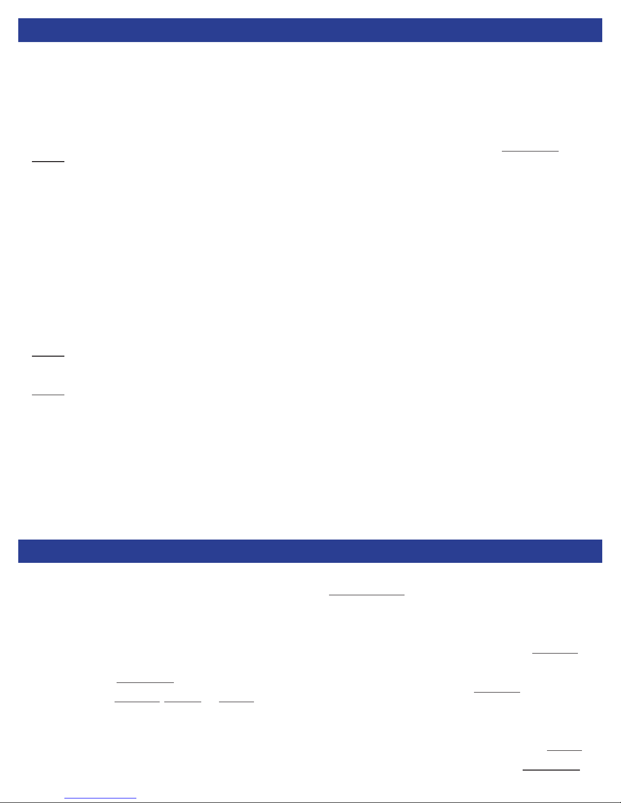
2. Unscrew the connector/socket assembly from the back of the light body
using your hand or a 1 3/8” wrench. Gently pull the connector/socket assembly
away from the light body and unscrew the lamp base (the thing with wires run-
ning to it) from the socket in the connector/socket assembly. Remove the o-ring
(2-213 NO674-70) from the connector/socket assembly. Place all items in a
clean, dry place.
3. Unscrew the retaining cowl using a large size spanner wrench to hold the
cowl and a small size spanner wrench to hold the light body.
4. Optional: If you wish to remove the retaining cowl and locking ring, do so
before separating the lighthead from the body. Once the retaining cowl is loos-
ened, retighten it so that it is just hand tight. This gives the locking ring some
resistance to hold it out of the way during removal of the retaining cowl. Using a
small allen wrench or screwdriver, press in on the locking ring through the small
sight holes in the retaining cowl. Work your way around the cowl until the lock-
ing ring has bottomed out in the groove in the lighthead. Pull the lighthead di-
rectly away from the body and cowl to separate it. This process may need to be
repeated several times before the lighthead releases. This process takes some
practice, and care should be taken not to damage or force any of the parts.
5. Carefully separate the lighthead from the body making sure that the lamp
base passes through the connector/socket assembly hole. The retaining cowl
will remain connected to the lighthead, if you have not removed it already.
6. Remove the o-ring (2-037-NO674-70) from the back side of the lighthead.
Place in a clean dry place.
7.
8. Optional: If you wish to replace the driver board, remove it by unscrewing the
four screws that hold it to the light engine. Carefully unplug the green connec-
tor that attaches the lighthead to the driver board. Place all parts in a clean dry
place.
9. Optional: If you wish to remove the mounting collar, unscrew the allen head
screw at the top of the collar. With your thumbs on the rear of the light body
and your ngers on the collar, pull back on the collar while you push on the light
body. It may take considerable force to remove the collar. Once the collar has
been removed, remove the rubber mounting ring.
1. Inspect all o-rings to make sure that there are no nicks or cuts present, and
that they are still supple and exible. Clean with a lint free wipe and reagent
grade alcohol.
2.
The front window of the lighthead is made of acrylic plastic and will
cloud and craze if exposed the alcohol.
3. Clean the o-ring groove on the back of the lighthead with a lint free wipe.
Check the wires that connect the lamp base to the driver board for nicks or
wear.
4. Inspect the light body to make sure that it is clean, and that the sealing sur-
faces on the front and back are smooth and free of scratches or rough spots.
Check the entire body for evidence of corrosion.
5. Inspect the retaining cowl for cracks or chips.
6. Inspect the connector/socket assembly for wear. Clean the o-ring groove
with a lint free wipe and reagent grade alcohol. This is also a good time to
check the continuity of the connector/socket assembly.
7. If any of the above parts show signs of wear or damage they should be
replaced. If there appears to be anything wrong with the lighthead, it should be
returned to DSPL for evaluation and repair using the RMA procedure.
1. If you removed the mounting collar from the light body, reinstall the rubber
mounting ring rst, making sure that the rounded corner of the ring is on the
outside and facing the rear of the body. Place the light body face down on a at
surface. Loosen or remove the allen head screw in the collar. Place the collar
over the light body making sure that the ridge on the inside edge of the collar is
on top. Press rmly on the collar until it is seated over the rubber mounting ring.
Tighten the allen head screw.
2. Place the lighthead/driver assembly face down on the at surface.
3. If you separated the driver board from the lighthead, reinstall the driver board
by plugging the green connector back into the driver board. Make sure that the
thermal pad is sitting on top of the FET (black, D shaped component on the
driver board) and that it contacts the lighthead body when the driver board is
seated.. Reinstall the 4 screws, shoulder washers and spacers that hold the
board to the light engine.
4. If you removed the retaining cowl and locking ring, reinstall them by com-
pressing the locking ring in the groove in the lighthead with your hand while
lowering the retaining cowl onto the lighthead.
5. Lubricate the o-ring (2-037-NO674-70) with Dow 111 and place it into the
groove in the back of the lighthead.
6. Lower the body onto the lighthead and sh the lamp base through the hole
where the connector/socket assembly will go using tweezers or needle-nose
pliers.
7. Tighten the retaining cowl, rst by hand, and then using the spanner wrench-
es until it feels snug and no threads remain visible.
Look through the larger sight holes in the retaining cowl to
make sure that the lighthead and body are in contact all the way around.
8. Lubricate and reinstall the o-ring (2-213-NO674-70) into the groove in the
connector/socket assembly.
9. Screw the lamp base into the socket in the connector/socket assembly. Ro-
tate the connector/socket assembly three full revolutions in a counterclockwise
direction to preload the wires that connect the lamp base to the driver board.
Screw the connector/socket assembly into the back of the light body until hand
tight.
10. It is recommended that the light be pressure tested once reassembled. If
pressure testing facilities are not available, soak the light in clean, fresh water
for several hours to insure that the light is sealed.
If the light stops working while underwater, you should assume that it has been
ooded. When working on a potentially ooded light, it is important to use
appropriate personal protective equipment to include, at a minimum, eye and
hand protection.
1. Place the light face down on a table making sure that the connector side is
facing up.
2. Slowly unscrew the connector/socket assembly to allow any internal pres-
sure to be equalized.
3. Once it is determined that the light is not internally pressurized, it is recom-
mended that the light be returned to DeepSea Power & Light (DSPL) for evalu-
ation and repair using the RMA Procedure.
4. In case of emergency, you may attempt to repair the ooded light by follow-
ing the steps listed in the Disassembly, Inspection and Assembly procedures.
Any parts that were exposed to saltwater should be cleaned with de-ionized
water to remove any salt residue before reassembly. Make sure that all parts
are completely dry before reassembly by baking them in an oven at 140°F for
30 minutes.
1. If the light stops working while underwater assume that it has been ooded.
See Flooded Light Repair procedure.
2. Once it has been determined that the light is not ooded, or if it does not turn
on during pre-deployment checks, troubleshoot in the following sequence:
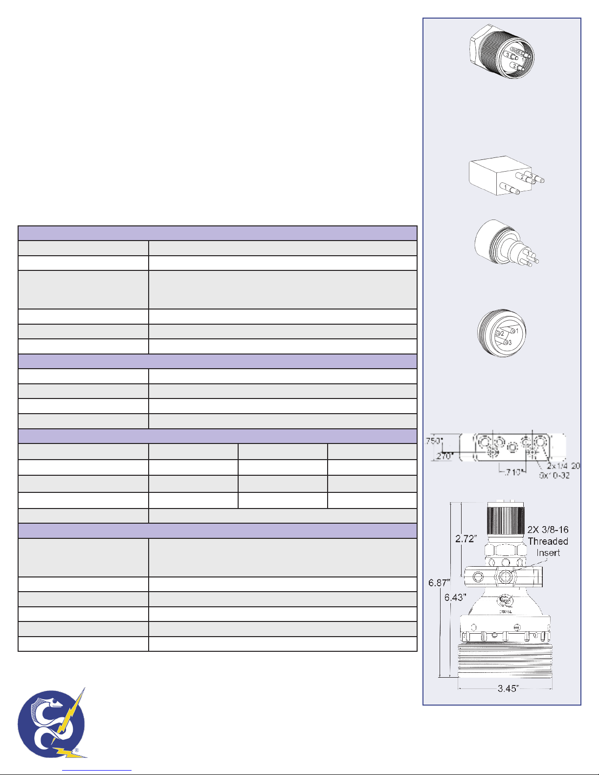
a. Check the power cable/inline connector to make sure that correct voltage
and current are being supplied, and that the correct sockets are being used.
See the back of this manual for electrical specs and connector pinouts.
b. Remove the connector/socket assembly (see step 1 in the Disassembly
procedure). Inspect the assembly for visual signs of wear. Using a multi-meter
check for continuity or shorts in the connector. Try a spare connector/socket
assembly if available.
c. Disassemble the rest of the light using the Disassembly procedure (steps 2
through 7).
d. Check the wires that go from the driver board to the lamp base for wear. If
they appear worn, replace the driver board.
e. Check to make sure that the driver board is securely attached to the
lighthead. If it is loose, check for damage on the board. If there appears to be
no damage, reattach the driver to the lighthead (see step 3 in the Assembly
procedure). Try using a spare driver board if available.
f. If the light still does not work, return it to DSPL using the RMA Procedure.