DefenderCab Kawasaki Teryx 750 User manual

1
Owner’s Manual
Model:
Kawasaki Teryx 750™
Caution:
Before using this
product, read this
manual and follow all
Safety Instructions.
Kawasaki Teryx 750 Cab Kit*
Safety Instructions
Cab Kit Contents
Hardware Assembly
Panel Assembly
Operation
*DefenderCab™and accessories are in no way affiliated
with Kawasaki Heavy Industries Ltd™. Any use of the name is only
to identify their utility vehicle as it pertains to our accessories.
Kawasaki and teryx are registered trademarks of Kawasaki heavy
industries Ltd.

2
Warning: Failure to heed all safety and operating instructions and
warnings regarding use of this product can result in serious bodily
injury.
SAFETY INSTRUCTIONS
Read entire assembly instructions
before beginning work.
Install all parts indicated in assembly
instructions. Failure to fully assemble
product before use could result in
personal injury.
Assembly of product requires use of hand
or power tools. If you are not experienced
in using these types of tools, have product
dealer do the installation for you.
Some parts contain sharp edges as
indicated in the manual. Wear protective
gloves if necessary.
Dress for safety. DO NOT wear loose
clothing, gloves, neckties or jewelry if
using power tools to assemble this
product.
Always keep your assembly area clean,
uncluttered and well lit.
Keep visitors and children a safe distance
away from the assembly area. Visitors
should wear the same safety equipment
described above.
Never operate your ATV with the cab
doors open. Failure to properly latch
the doors before moving the vehicle
could result in serious injury.

3
CAB KIT CONTENTS
Your DefenderCab™should contain the parts listed below. Separate all parts from
packing materials. Do not discard packing material until assembly is complete. Item
quantities are listed in parenthesis below.
Panels, Doors and Brackets
(1) Plastic Roof Panel
(1) Plastic Rear Panel
(1) Steel Windshield Panel
(1) Plastic Driver Side Panel
(1) Plastic Passenger Side Panel
(1) Steel Driver Door Assembly
(1) Steel Passenger Door Assembly
(2) Polycarbonate Door Window
(1) RH Hinge Mounting Bracket
(1) LH Hinge Mounting Bracket
(1) RH Striker Mounting Bracket
(1) LH Striker Mounting Bracket
(2) Upper Panel Bracket
(4) Door Adjuster Plate
(1) Baton Strip
(1) Rubber Dust Shield
Hardware
(2) RH Lift Off Hinge
(2) LH Lift Off Hinge
(2) Striker Plate
(14) Plastic Knobs
(1) 25ft Roll, Hard Gasket
(1) 25ft Roll, Soft Gasket
(6 ft.) Small Edge Trim
(2) M6 x 10mm Hex Bolt
(16) ¼-20 x 5/8” Flat Head Screw
(2) #10-32 x ¾” Screw, Nyloc, Washer
(38) ¼-20 x 5/8” Screw, Nyloc,
Washer
(4) ¼-20 HEAVY Nyloc Nut
(4) ¼-20 x 3/8” Screw
(6) U-Type Speed Clip
(2) Anti-Vibration Mount
(6) #8-32 Self Tapping Screw
TOOLS REQUIRED FOR ASSEMBLY
Ensure that you have the following tools available before you begin the assembly of your
DefenderCab™kit. Note: Assembly requires an assistant.
Phillips & Flat Screwdrivers
1/4” Wrench / Socket
1/2” Wrench / Socket
7/16” Wrench / Socket
5/32”Allen Wrench
10, 14 & 19mm Wrench / Socket
Electric drill
3/16” drill bit
1/4” drill bit
Utility knife
Utility Clamps or Locking Pliers
Rubber Mallet

4
C
Vehicle Preparation
1. Forward Bracketery
i) Remove seats and set aside for
better access to vehicle interior.
Refer to Owner’s Manual for
instructions.
ii) Remove lower foot guardrails and
set shoulder screws aside for later
use. Loosen 19mm bolts (Ain
Fig.1) until 3/16” gap can be
achieved.
iii) Loosely fasten anti-vibe mount (B
in Fig.1) to Hinge Mounting
Brackets using 6mm bolts. Mount
brackets to vehicle as shown in
Fig.1 and hand tighten 19mm bolts.
iv) Align lower bracket hole to
existing foot guard mounting hole
and fasten with OEM shoulder
screw (Cin Fig.1). NOTE: Apply
pressure to screwdriver in order
catch threads on nuts.
v) Adjust upper edge of brackets
with mallet to make bracket edge
flush to roll bar edge (Fig.2).
Tighten 19mm bolts. Adjust and
tighten rubber mounts.
FLUSH
A
B
Fig.2
Fig.1

5
2. Rear Bracketery
i) Remove 14mm bolts from lower
mounting points on rear crossbar.
Install Striker Mounting Brackets as
shown (Fig.3). Reinstall bolts and
hand tighten only. Attach Striker
Plates using (4) ¼-20 x 3/8” screws,
keep loose for later adjustment.
ii) Remove 14mm bolts from upper
crossbar and install Upper Rear
Panel Brackets as shown (Fig.4).
Tighten 14mm bolts back into place.
(Driver side shown from vehicle
exterior)
3. Panel Installation
i) Install low density foam to interior
of panels as shown (Fig.5.) Approx.
(8) 3” long strip are required on each
side panel. Install low density foam
to entire door / panel interface.
ii) Mount side panels to roll cage and
temporarily clamp to top roll bar.
Loosely insert remaining (2) shoulder
screws to each foot well. Adjust each
panel to obtain proper alignment at
front, top and lower rear.
iii) Ensure hinge mounting bracket
edges are flush with inside door
frame and transfer hinge bolt hole
locations onto plastic panels.
Remove panels and drill holes using
¼” bit. Re-install panels and
shoulder screws onto vehicle.
iv) Mount hinges as shown (Fig.6)
with (8) ¼-20 x 5/8” Lg. Flat Head
screws. DO NOT OVER TIGHTEN.
Fig. 3
Fig. 4
Fig. 5
Fig.6
UP
Interior

6
v) Hold lower side panel sections
firmly against vehicle body and
pierce (3) 3/16” holes through side
panel and underside of vehicle
rocker panel. Slide U-Type speed
clips onto rocker panel and fasten
side panels with (3) #8-32 screws
each.
4. Windshield Installation
i) Temporarily install windshield
panel onto vehicle; ensure panel is
horizontal and is aligned identically
on both sides of vehicle. Use an
erasable marker to transfer bottom
edge of panel to hood surface
(Fig.8). Remove panel when done.
ii) Adhere high density foam strip to
hood using marker line as centerline
guide to ensure windshield panel will
sit squarely onto foam after
installation. Install small edge trim to
side edges of windshield and cut to
suit. Install small edge trim to lower
edge of windshield.
iii) Re-install windshield panel onto
vehicle and have an assistant hold
and press windshield panel down
onto foam strip as tightly as possible.
Line up small side edges of plastic
panels (Din Fig.9) to outer wind-
shield panel edges and transfer
holes (Ein Fig.9) onto plastic panels
using 1/4” drill bit. Secure panel with
(10) ¼-20 x 5/8” Lg. screws, washers
and nyloc nuts.
Fig.8
D
E
Fig.9
Clip onto rocker panel
Fig. 7
7
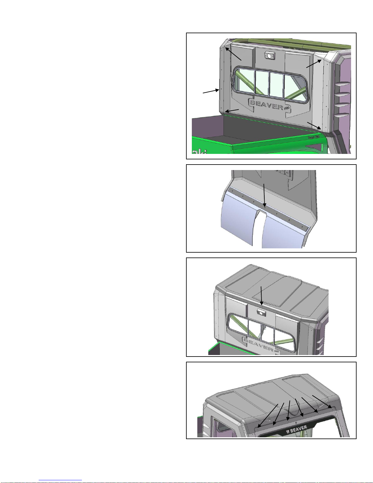
5. Back Panel Installation
i) With help from an assistant, mount
rear panel inside plastic side panels.
If needed, use temporary clamps to
hold and align bends and edges to
ensure a clean fit (Fin Fig.10). Using
a ¼”drill bit, transfer holes onto back
panel (Gin Fig.10). Secure panels
with (8) ¼-20 x 5/8” Lg. screws,
washers and nyloc nuts.
ii) Center and clamp Rubber Dust
Shield and Baton Strip to lower edge
of back panel. Transfer baton strip
holes to rubber shield and back
panel using a ¼” drill bit (Fig.11).
Secure with (7) ¼-20 x 1” Lg.
screws, washers and nyloc nuts.
Note: Baton Strip should be located
above or below panel bend line to
avoid hardware interference with box
tilt operation.
6. Roof Panel Installation
i) Install roof panel and note roll bar
contact points. Adhere foam strips if
desired. Press down onto rear center
section of roof and line up panel
edge to back panel bend line.
Transfer middle hole to back panel
and secure temporarily. (Fig.12)
ii) Have an assistant hold down and
level the front portion of the roof
panel. Stand away from the vehicle
and ensure that the roof looks level
from all angles. Once satisfied with
the look, transfer windshield panel
holes from inside of vehicle to roof
panel with ¼” drill bit. Secure with
1/4-20 x 5/8” Lg. screws, washers
and nyloc nuts. (Fig.13)
Fig.10
Fig.11
F
F
F
F
G
Fig. 12
Fig. 13
8
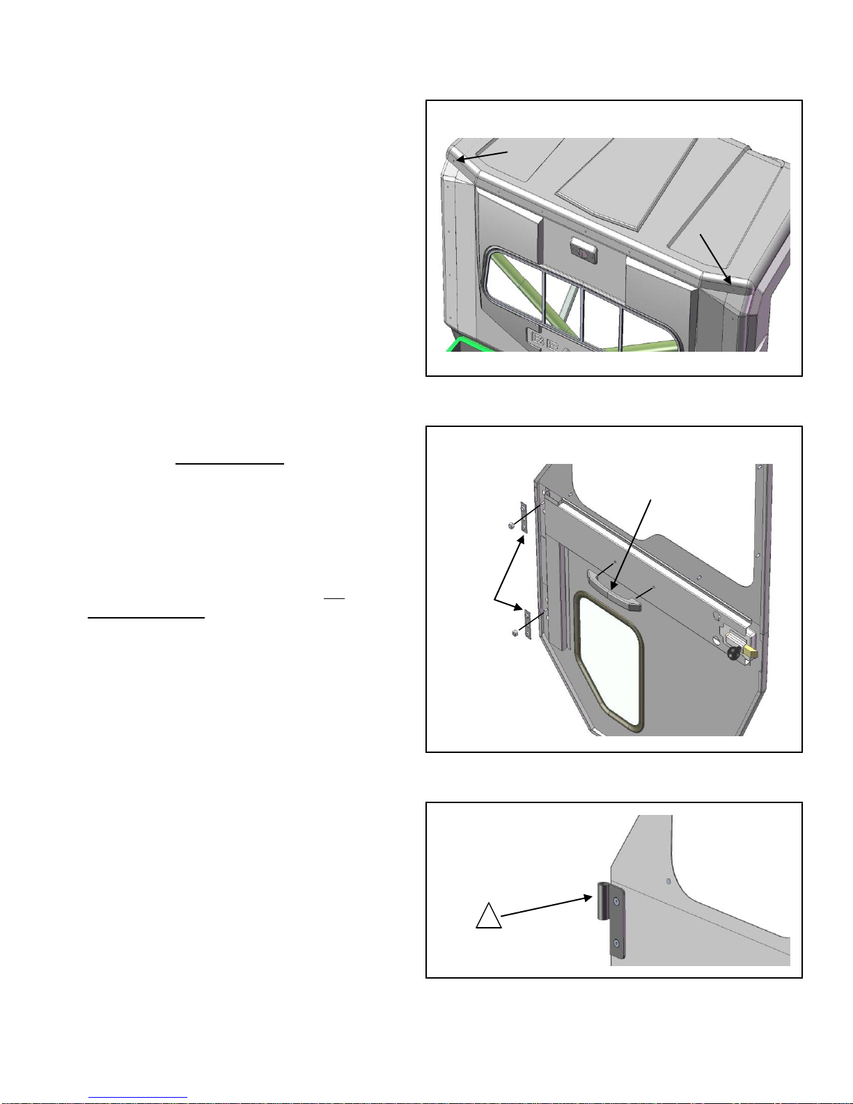
iii)Align remainder of roof panel to
back panel and transfer remaining
holes onto rear and side panels.
(NOTE: A proper finish at corners is
better achieved by firmly holding
panels from interior while drilling
through [Hin Fig.14]). Secure with
(7) ¼-20 x 5/8” Lg. screws, washers
and nyloc nuts.
6. Door Preparation / Installation
i) Mount door adjuster plates (Jin
Fig. 15) to inside of door (2 plates
per door) with heavy (large) ¼-20
Nyloc nuts. Do not tighten. Install
inside door handle with #10-32 x ½”
screws. (Kin Fig.14)
ii)Install proper hinges (Fig.16) to
door panels using (8) remaining ¼-
20 x 5/8” Lg. Flat Head screws. Do
not fully tighten.
iii) Mount doors to vehicle. Shim
bottom edge of door as required in
order to obtain equal spacing at top,
bottom and back edges. Reach
through window opening and tighten
¼” nuts followed by exterior hinge
screws –DO NOT OVER TIGHTEN.
Ensure door swings freely within
frame; adjust if necessary.
iv) Push door into frame until flush
with plastic panel surface in latch
area. Reach inside and adjust striker
plate depth (Lin Fig.17)
Fig. 14
H
H
J
Fig.15
K
Driver door shown
!
Fig. 16
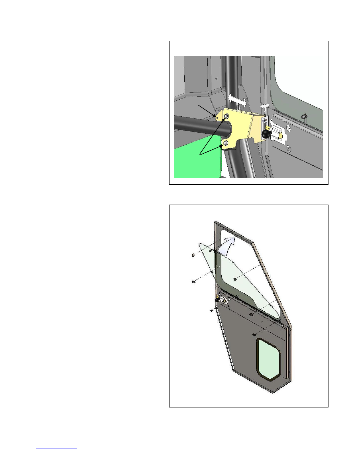
9
v) Open and close door. Adjust
amount of latch / striker plate
interface by moving striker mounting
bracket towards front or back of
vehicle until door closes firmly (Min
Fig. 17). Tighten rear lower cross
brace 14mm bolts (Nin Fig.17).
(NOTE: Plastic panel door frame
may require trimming on some
units.)
vi) -Optional-Transfer bracket hole
(Pin Fig.17) to back panel and install
#10-32 x ¾” Lg. screw, washer and
nyloc.
vii) Install seats and ensure proper
door operation.
7. Window Operation
i) Install windows onto doors by
sliding bottom edge in first. Secure
window with (7) plastic knobs per
door.
L
M
N
Fig. 17
Fig. 18
P

10
OPERATION
The DefenderCab™with removable doors is very useful for work or play. It is perfect for
the hunting, farming, fishing, commercial and recreational enthusiast. The cab and optional
heater allow the full enjoyment of the vehicle in all weather conditions.
Removing the doors
In warm weather or to load your ATV on a
trailer, the doors of your hard cab can be
easily removed by opening the door and
carefully lifting it off the hinges.
Removing the windows only
In warm weather, the windows of your
hard cab can be removed to provide
ventilation.
Cleaning your DefenderCab™
Use same mild soap and techniques used
to clean your ATV
To order replacement parts, contact the Parts Department at:
LB Manufacturing Inc.
247 Arsenault Road,
Dieppe, N.B Canada
E1A 7J5
Ph: (506) 388-9334 Fax (506) 388-3325
www.defendercab.com
Manual Revision: 2.0 Date: 26 October, 2012
This manual suits for next models
1
Table of contents
Popular Automobile Accessories manuals by other brands

Safe Fleet
Safe Fleet RVS G Series instruction manual

Phonocar
Phonocar 5/030 Mounting instructions

Motorola
Motorola MTP6000 SERIES installation guide

Whispbar
Whispbar K987W Fitting instructions

BTCPower
BTCPower L3S2-50-400 Series Installation and user manual

NORAUTO
NORAUTO 2274266-NO0531-608 owner's manual

Prorack
Prorack K1104 manual

Ironman4x4
Ironman4x4 IUP002E installation instructions

Black Horse Off Road
Black Horse Off Road 17G80330MSS installation instructions

Metra Electronics
Metra Electronics 955822 installation instructions

Roadmaster
Roadmaster 76515 installation instructions

Thetford
Thetford SANICON TURBO 300 manual


