Rock Tamers 00108 User manual

RUINST CTION MANUAL
IMPORTANT!
P l ea s e R ea d B o o k l et prior to a s s em b l y of
y our R ock T amer K it.
Removable and Adjustable Mudflap System
CLEARVIEWACCESSORIS.COM.AU
& MESH


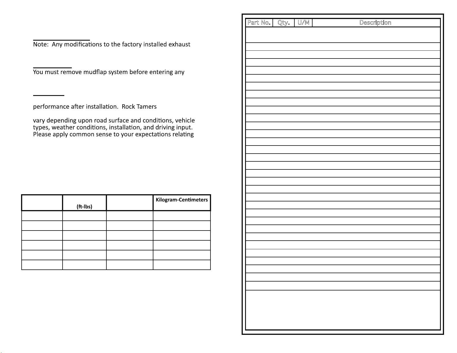
Bolt Torque Conversion Table
1
IMPORTANT!
Exhaust Systems
system may void your manufacturer’s warranty.
Car Washes
drive-through car wash.
CAUTION
Consumer assumes all risks associated with product
TM will not
protect everything and everyone from harm. Results may
to product performance.
This product can expose you to chemicals including chromium,
which is known to the state of California to cause cancer.
For more informa�on go to www.p65warnings.ca.gov
Inch-Pounds
(in-lbs)
Foot-Pounds Newton-Meters
(N-m) (kgf-cm)
20 1.7 2.3 23
30 2.5 3.4 34
70 5.87 7.9 79
80 6.7 9.0 90
180 15 20 203
1500 125 169 1690
2
Part No. Qty. U/M Description
RT034
RT035 2 EA M10 Ball Mount Clamp Bolt*
RT036 2 EA M10 Jam Nut*
RT037 2 EA M10 Split Washer*
RT038 2 EA M10 Flat Washer *
RT039 1 EA Hub Arm R (Right) / Matte Black Finish*
RT040 1 EA Hub Arm L (Left) / Matte Black Finish*
RT041 6 EA M6 Arm Clamp Bolt*
RT032 6 EA M6 Nylon Insert Hex Nut*
RT042 2 EA M18 Arm Pivot Bolt*
RT043 2 EA M18 Split Washer*
RT044 2 EA M18 Flat Washer*
RT027 1 EA 5mm Allen Wrench - Solid (Black)
RT045 2 EA Flap Support Rod (Stainless Sleeved )
RT046 2 EA Rod End Cap
RT017 2 EA Flap End Cap
RT018 2 EA M5 Flap Retainer Bolt (Round Head)
RT047 2 EA M5 End Cap Bolt (Hex Head)
RT019 4 EA M5 Nylon Insert Hex Nut
RT048 2 EA Flap Clamp / Matte Black Finish
RT022 2 EA Mudflap (SS Trim Plate)
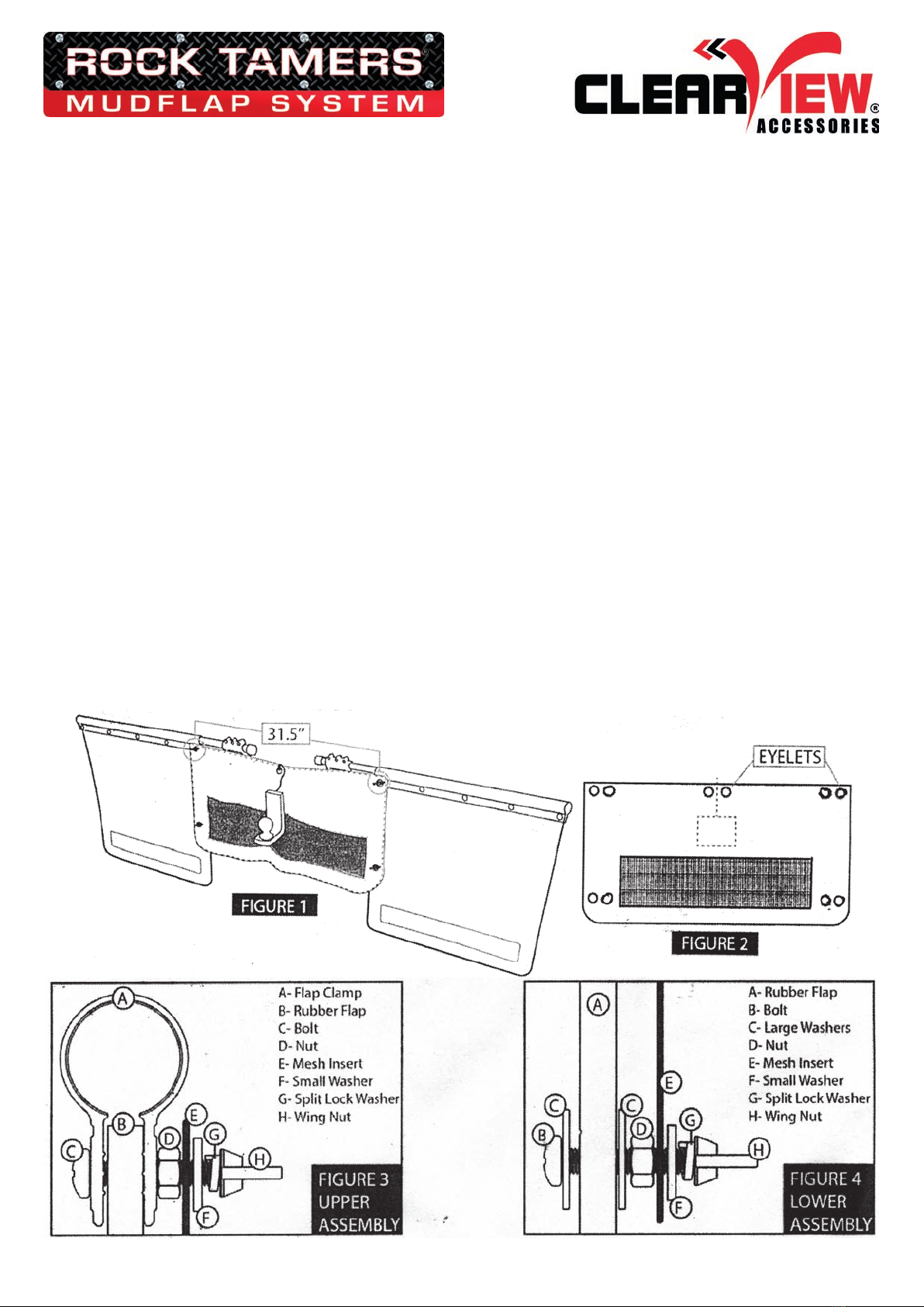
RT023 10 EA M8 Flap Clamp Bolt
RT024 10 EA M8 Flat Washer
RT025 10 EA M8 Nylon Insert Hex Nut
RT026 1 EA Bolt Hole Punch (Black)
RT028 2 EA Rock Tamers Trim Plate
RT049 16 EA M6 Trim Plate Bolt (STAR PIN
TM
)
RT030 16 EA M6 Trim Plate Spacer
RT031 16 EA M6 Flat Washer
RT032 16 EA M6 Nylon Insert Hex Nut
RT050 1 EA Locking STAR PIN
TM
Wrench (Black)
IM002 1 EA 00108/00110/00112 Instruction Manual
* HUB ASSEMBLY - FACTORY ASSEMBLED
1 EA 2.0" Center Hub/Matte Black Finish.*
(Only if 00108 is purchased.)

Assembly Hints
• Refer to Figure 1
MOUNT on the vehicle. However, it may also be assembled on a
•vehicle. Be sure of the required length by measuring with full
3
Tools Required
a. Wrench or socket sizes:
–8mm, 10mm, 13mm, 17mm, & 27mm
(or a wrench adjustable up to 1 1/8” or 27mm)
– Locking STAR PINTM wrench included
–5mm locking Allen wrench included
e. Hammer or mallet
4
Figure 1

Figure 3
Figure 4
Figure 2
1. Slide HUB ASSEMBLY
onto BALL MOUNT
and insert into vehicle
RECEIVER HITCH.
See Figures 2 & 3.
Assembly Instructions
Account for all parts listed in the Parts List.
2. Secure the BALL
MOUNT with HITCH
PIN. Adjust HUB
ASSEMBLY to desired
3. Tighten the two M10
BALL MOUNT CLAMP
BOLTS to hold
CENTER HUB in place.
(For assembly only)
See Figure 3.
4. Loosen or Remove
all three M6 ARM
CLAMP BOLTS from
each HUB ARM.
Carefully insert
the two FLAP
SUPPORT RODS
thru HUB ARMS.
Place ROD END
CAP over the end
of rods, hex side
facing away from
vehicle, insert
END CAP BOLT
thru END CAP
BOLT HOLE,
with M5 NYLON
INSERT HEX NUT.
See Figure 4.
5
5. Re-install M6 ARM CLAMP BOLTS and M6 NYLON INSERT HEX NUTS
back in (Do not
adjustment holes face forward horizontally. Figure 5.
7. Slide FLAP CLAMPS over the FLAP SUPPORT RODS with square
holes facing away from vehicle. Do not secure with FLAP RETAINER
BOLTS yet. (See Figure 6
Figure 6.
6
Figure 5
Figure 6

Figure 7
Figure 8
MUDFLAP SYSTEM is properly installed. All measurements should
be made while tow vehicle has full tongue weight.
8. Make sure SUPPORT RODS are level on both sides and measure
the dis
ground. Subtract the desired ground clearance (3”- 4”
recommended or 75 mm – 100 mm). Figure 7.
pre-molded CUT LINE GROOVE and mark. Figure 8.
IMPORTANT:
drilling/punching
holes, make sure to
place either a scrap
piece of wood or thick
cardboard underneath
MUDFLAP to avoid
any surface damage.
7
IMPORTANT: Place a scrap piece of wood under the MUD FLAPS
when punching or drilling holes, as the punch will dull and may
damage the surface underneath.
Figure 9
groove and a straight edge as a guide. This may take several
passes to completely cut through MUDFLAP. See Figure 8.
Repeat procedure for 2nd MUDFLAP.
11. Punch the top row of pre-molded holes in the MUDFLAP
using the included BOLT HOLE PUNCH. Figure 9.
8

12. Assemble cut end of MUDFLAP into FLAP CLAMP by either sliding
or pushing it down onto top of MUDFLAP with the square holes
on the smooth side.
Note:
Figure 10.
Repeat for 2nd MUDFLAP.
9
SUPPORT ROD with the NYLON INSERT HEX NUTS facing your
vehicle.
as desired for your vehicle. Line up small hole in FLAP CLAMP
depending on vehicle size.
• Inner Hole - for small and mid-sized vehicles
• Center Hole - for full-size vehicles
• Outer Hole - for large vehicles, such as dually trucks and
small motor homes
Finally, insert the small M5 FLAP RETAINER BOLT through
HEX NUT. Figures 1 & 6.
Repeat for 2nd MUDFLAP.
14. Assemble TRIM PLATES. Insert M6 TRIM PLATE SPACERS into
TAMERS TRIM PLATE with the eight M6 TRIM PLATE BOLTS
(Locking STAR PINTM [STAR PINTM wrench included]), M6 FLAT
WASHERS, and M6 NYLON INSERT HEX NUTS as shown in
Figure 10. (20 in-lbs torque [10 mm socket or wrench]).
Repeat for 2nd MUDFLAP.
Note:
Figure 10
15. The ARMS of the
HUB ASSEMBLY may
be loosened and
The FLAP SUPPORT
RODS must also
be rotated slightly so
the MUDFLAPS hang
Figure 11.
10
Figure 11

Figure 12
Torque conversion table on page 1.
17. Make sure the M10 SPLIT WASHERS and M10 JAM NUTS remain
(120-180 in-lbs torque [17 mm socket or wrench]).
the M10 WASHERS AND JAM NUTS securely. Figure 12.
18. Tighten the large CENTER HUB M18 ARM PIVOT BOLTS. (1500 in-
lbs torque [27mm socket or wrench]). Figure 1.
Note: Make sure the ARM PIVOT BOLTS and SUPPORT RODS
not rub up against it.
19. Finalize width adjustment of FLAP SUPPORT RODS by sliding them
in or out of the HUB ARMS. Figure 5.
11
beginning with the center bolt and moving from one to another on
The SLOT will NOT close. (70-80 in-lbs torque [5mm ALLEN
WRENCH]).
Notes: extends
CLAMPS. Figure 10. (30 in-lbs torque [13mm socket or
wrench])
IMPORTANT: SUPPORT RODS MUST NOT BE ABLE TO ROTATE or
MOVE IN HUB ARMS or FLAP CLAMPS.
21. Tighten the M5 FLAP RETAINER BOLTS on each side. Figure 6
IMPORTANT: FLAP RETAINER BOLTS are not intended to hold FLAP
CLAMP on FLAP SUPPORT ROD. The RETAINER BOLTS must be used
FLAP CLAMPS. Figure 1.
12

components and the torque on all bolts prior to each use.
Figure 13.
> FORGED ALUMINUM HUB & ARMS
> STAINLESS SLEEVED STEEL RODS
> UV PROTECTED MATTE
BLACK FINISH
>STAINLESS, CHROME
AND ZINC PLATED
HARDWARE
Figure 13
13 14
3 Frog Court, Craigieburn VIC 3064
(03) 7379 4138 (03) 8351 9933
clearviewaccessories.com.au

INSTALLATION INSTRUCTIONS FOR
ROCK TAMERS MESH INSERTS 33.5” (850mm)
1. Set width of rubber aps to approximately 31.5” between the rst Flap Clamp Bolts on each side (see Figure 1).
2. Remove the 2 Flap Clamp Bolts, replace them with 2 included bolts with thread facing away from vehicle.
Lock bolts into posion using a nut, ghten to 30 in-lbs (see Figure 3).
*NOTE THAT HARDWARE SHOULD BE SAVED FOR FUTURE USE.
3. Place the Mesh Insert on these bolts, mark the locaon of the hole and slot that will be cut for the ball-mount
on the Mesh Insert.
4. With the Mesh Insert sll in place, mark the locaon of the lower 2 eyelets on the rubber aps.
5. Place the Mesh Insert on a scrap piece of wood and cut the hole and slot using a sharp blade.
(see doed line in Figure 2)
*NOTE THAT THE SLOT, IF REQUIRED, SHOULD BE CUT BETWEEN THE 2 TOP CENTRE EYELETS.
6. Drill 1/4” holes in the rubber aps, corresponding with the markings from the lower eyelets.
*NOTE THAT THE RUBBER FLAPS SHOULD BE PLACED ON A SCRAP PIECE OF WOOD, ON A SOLID SURFACE.
7. Insert a bolt, with 1 large washer, into the hole in the rubber ap with the thread facing away from the vehicle.
8. Place another large washer over the lower bolt, then lock the bolt into posion using a nut (see Figure 4).
9. Repeat steps 7 & 8 on the other rubber ap.
10. Place the Mesh Insert over the 4 bolts and secure in place using 4 small washers, 4 split lock washers and
4 wing nuts.
11. Lace the 2 top centre eyelets together using zip e or string (not included).
NOTE • Addional access slots can be cut for power leads, chains, etc.
• The Mesh Insert is a disposable item.
• The life of the Mesh Insert will vary depending on road condions and speed.
• A loose-ng mesh will last longer than a ght-ng mesh.
Clearview Accessories
www.clearviewaccessories.com.au
Quesons or Concerns?
03 8351 9933
Other manuals for 00108
1
This manual suits for next models
1
Other Rock Tamers Automobile Accessories manuals