Test the system
1. Follow each of the steps in the owner's manual up to the
point where it tells you to remove the fuse.
2. Verify there is voltage on the large red wire at the control-
ler. If not, be sure the fuse is installed in the FuseMaster fuse-
holder. If still no voltage, check for proper connection of this
wire to the socket. Remember this is the socket that registered
voltage when the car was in ‘tow' mode.
3. Once you've verified voltage is present on the large red
wire, test for voltage on the large black wire at the controller. If
there is no voltage, rock the switch to the ‘drive' position. You
should now have voltage. If not, check the fuse on the orange
wire. If voltage is still not present on the large black wire, then
rock the switch to ‘tow' position. If voltage is now present, the
labels are reversed. Simply rotate the switch 180 degrees.
4. If you have voltage on the large red and large black wire
at the controller, then you are in ‘drive' mode and the vehicle
should start. If not, verify the large black wire is inserted prop-
erly into the fuse block.
5. FuseMaster is operating properly if each of the above
conditions are met. When done testing, be sure to follow the
directions in the owner's manual to put the vehicle back into
‘drive' mode.
continued from preceding page
• The switch must not interfere with the operation of the
vehicle in any way.
• There must be enough space for the included ‘tow' and
‘drive' decals, which will be attached in close proximity to the
switch.
3. The large red and black wires will be routed through two
3/8" access holes in the fuse block cover.
Drill the holes in the fuse block cover, over the points you
marked in step 1.
4. Put the vehicle in ‘tow’ mode. Connect a volt meter or test
light between the fuse socket and ground. Find which one of
the fuse sockets has voltage with the vehicle in ‘tow' mode.
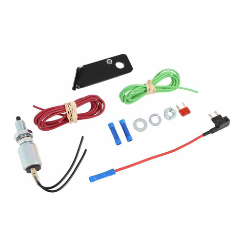
Insert the blade (Figure 1) of the large red wire through the
hole in the cover and into the socket that registers voltage.
CAUTION
If the blade on the red wire isn't inserted into the socket
that registers voltage, FuseMaster will not function.
Insert the blade of the large black wire into the other socket.
5. Gently press the blades down until they are fully seated,
and replace the fuse holder cover.
6. Push the grommets (Figure 1) into the access holes until
they snap in place.
7. In the passenger compartment, drill a 13/16" hole for the
switch at the mounting location you chose earlier.
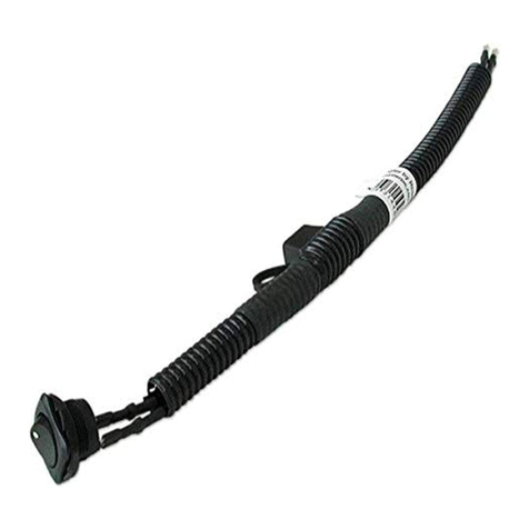
8. Route the harness through the hole to the fuse controller.
Insert the switch into the hole. It will snap into place when the
edge of the switch is flush to the mounting surface.
9. Use one or more of the included zip ties, if necessary, to
secure the harness.
10. Using the two self-tapping screws, the adhesive pad or zip
ties, attach the fuse controller at the location you chose.
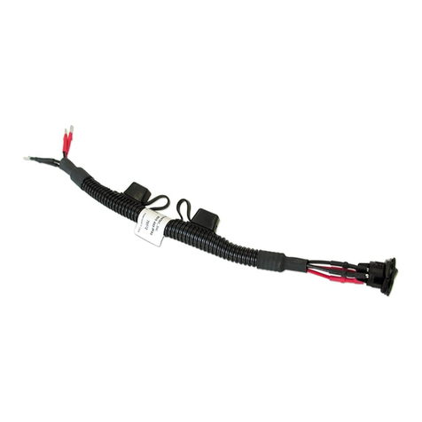
11. With the two included red butt connectors, connect the
red and black harness wires to the twisted pair of red and black
wires on the fuse controller (Figure 3). Match color to color.
Use the ring terminal to attach the white wire on the har-
ness to any good chassis ground.
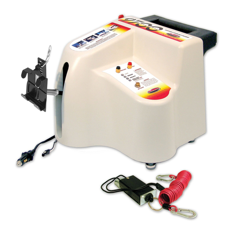
12. Install the small fuse holder — crimp the included ring ter-
minal onto the small fuse holder; attach the small fuse holder
to the controller as shown in Figures 1 and 3.
13. Seal the harness at the firewall with silicone sealant (not
provided).
Note: failure to seal the hole may allow water into the pas-
senger compartment, as well as allowing the wires to chafe or
short out.
14. Insert the fuse you removed in step 1 into the large fuse
holder (Figure 1), and close the protective cap over the fuse
holder.
15. Press the momentary switch and release. With a volt meter
or test light, check to see if voltage registers on the large black
wire on the controller. If it does, the vehicle is in the ‘drive’ mode.
If it does not, the vehicle is in the ‘tow’ mode.
Position the ‘Drive’ and ‘Tow’ stickers at the appropriate
sides of the switch.
Note: the switch may be rotated to be in line with the de-
cals.
16. Test the system, as described in the next section.
Figure 3
