Defensor Defensor H15A User manual

SERVICE MANUAL
2543355 EN 1310
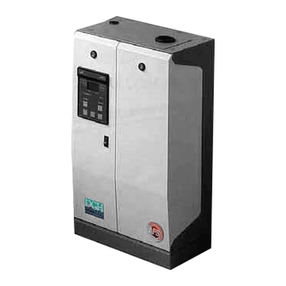
Adiabatic Humidifiers
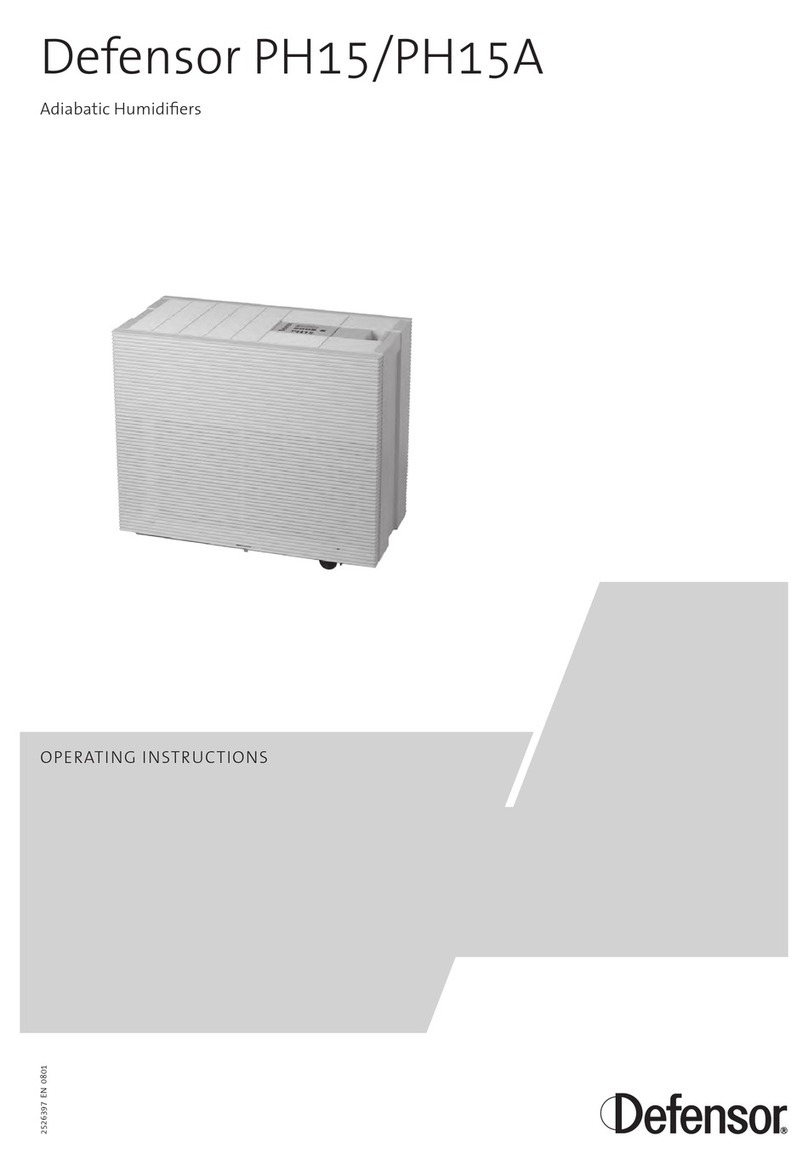
Defensor PH15/PH15A
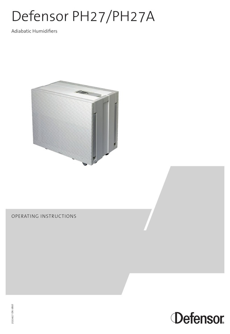
Defensor PH27/PH27A
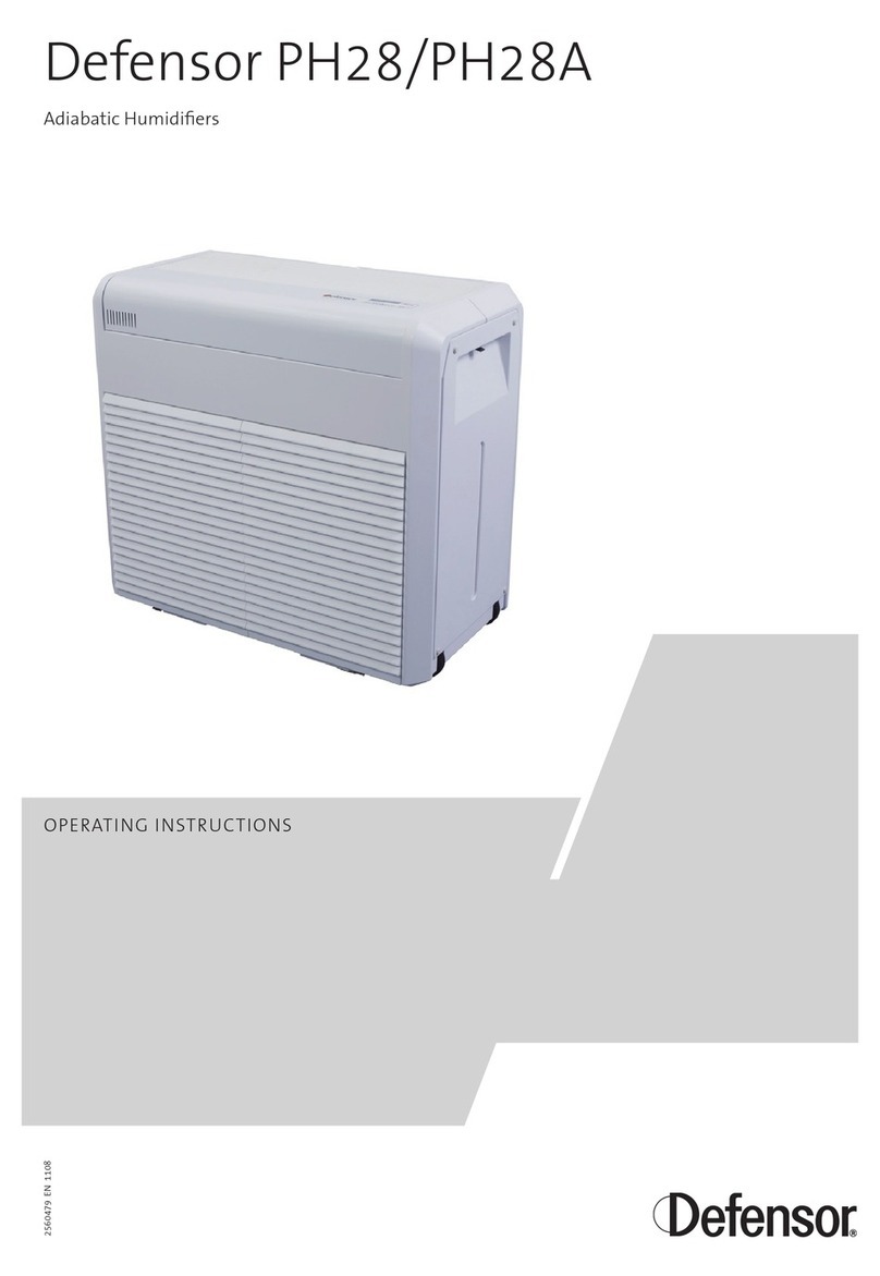
Defensor PH28/PH28A
For internal use only!


3
Contents
1 Introduction 4
2 Working with the service and diagnostic level 5
2.1 Overview service and diagnostic level 5
2.2 Settings in the service level 6
2.2.1 Viewing/deleting the error list 6
2.2.2 Setting the correction value for the internal humidity sensor 6
2.2.3 Setting the correction value for the external radio humidity sensor 7
2.2.4 Selecting the signal source from which the actual humidity value is taken 7
2.2.5 Modifying the remaining operation time until
a filter change warning is triggered 8
2.2.6 Calling the diagnostic level 8
2.2.7 Setting the unit type 9
2.2.8 Interrogation of the software version 9
2.3 Diagnostic level 10
2.3.1 Selecting the diagnostic level 10
2.3.2 Operating status of the carriage/rear cover lock switch 10
2.3.3 Operating status of the leakage sensor (option) 10
2.3.4 Operating status of the level switch 11
2.3.5 Operating status of the safety switch 11
2.3.6 Opening and closing the inlet valve Y1 12
2.3.7 Opening and closing the inlet valve Y2 12
2.3.8 Checking the fan levels 13
2.3.9 Switching on and off the centrifuge/drum drive 13
2.3.10 Checking the error relay 14
2.3.11 Checking the error LED (red) 14
2.3.12 Checking the operation LED (no function) 15
2.3.13 Checking the safety valve relay KY1 15
2.3.14 Checking the buzzer 16
2.3.15 Resetting the unit to factory default settings 16
3 Installation of options 17
3.1 Installation of the silver ionization (for PH15/PH15A only) 17
3.2 Installation and commissioning of the external radio humidity sensor 20
3.3 Installation of the leakage sensor (PH15/PH15A and PH27/PH27A) 23
3.3.1 Installation of the leakage sensor (PH15/PH15A) 23
3.3.2 Installation of the leakage sensor for PH27/PH27A 25
4 Replacing unit components 27
4.1 Replacing the level switch/safety switch 27
4.1.1 Replacing the level switch/safety switch on the PH15/PH15A 27
4.1.2 Replacing the level switch/safety switch on the PH27/PH27A 28
4.1.3 Replacing the level switch/safety switch on the PH28/PH28A 29
4.2 Replacing silver ionization rods 31
4.2.1 Replacing silver ionization rods on the PH15/PH15A 32
4.2.2 Replacing silver ionization rods on the PH27/PH27A 33
4.2.3 Replacing silver ionization rods on the PH28/PH28A 34
4.3 Replacing the control board 35
5 Fault elimination 37
5.1 Event messages 37
5.2 Warning messages 37
5.3 Error messages 38
5.4 What, if...? 39
6 Appendix 41
6.1 Wiring diagram PH15/PH15A 41
6.2 Wiring diagram PH27/PH27A 42
6.3 Wiring diagram PH28/PH28A 43

4
1 Introduction
This service manual is meant for well trained service personnel, which is entrusted with the service
and repair work on the Defensor PH15/PH15A, Defensor PH27/PH27A or Defensor PH28/PH28A.
The service manual is a supplement of the existing operating instructions of the Defensor PH15/
PH15A, Defensor PH27/PH27A and the Defensor PH28/PH28A. It is assumed that the service per-
sonnel in charge with service and repair work has read and understood these operating instructions,
particularly the safety instructions.

5
Cover
Closed
Leakage sensor
Open
Float switch
Closed
Sec.float switch
Closed
Valve Y1
Closed
Valve Y2
Closed
Error History
8/8/6/6
Calibr. Internal
+ 2%rH Act:38%rH
Calibr. Radio
+ 2%rH Act:38%rH
Act.Value Source
Internal
Filter
0000
Diagnostic
Program
Model type
PHXX
2 Working with the service and diagnostic level
2.1 Overview service and diagnostic level
Software
VX.XX
Drive
Off
Error relay
Off
LED1 Error
Off
LED2 Operation
Off
Relais KY1
Off
Buzzer
0
Fan power
0
EEPROM
Clear
Code
8808
+>3 s
Code wrong
Service level Diagnostic level
Call service level: Press both arrow keys until the
code entry display appears (approx. 3 seconds).
**
PHXX
Act 38%rH B2
Act 38%rH B2
Set 45%rH
PH28/PH28A
PH15/PH15A / PH27/PH27A

6
2.2 Settings in the service level
2.2.1 Viewing/deleting the error list
Delete error list:
press <Enter> key >3 seconds
With this function you can view the error list with the last 4 malfunctions occurred and if required,
delete the error list.
Note: The error list can give you important information for the elimination of malfunctions.Therefore
the error list should be deleted only, after a possible malfunction has been eliminated.
Error History
Error History
1/4/1/2
(see chapter 2.2.8)
(see chapter 2.2.2)
With this function you can determine a correction value, if the actual value of the integrated humidity
sensor deviates from the value of a certified humidity measuring instrument.
Note: Before the sensor is calibrated or the correction value is determined, the unit should have been
some hours in the operation, so that the air around the sensor can adapt itself to the ambient air.
Setting range: -20 %rh ... +20 %rh
Factory setting: 0 %rh
2.2.2 Setting the correction value for the internal humidity sensor
Calibr. Internal
+02 %rH
Calibr. Internal
New Value
Calibr. Internal
Old Value
Calibr. Internal
+02%rH Act:38%rH
(see chapter 2.2.1)
(see chapter 2.2.3)
modify
confirm
cancel
- 20%rh ... + 20%rh

7
Act.Value Source
Internal
Act.Value Source
New Value
Act.Value Source
Old Value
Act.Value Source
Internal
2.2.4 Selecting the signal source from which the actual humidity value is taken
(see chapter 2.2.3)
(see chapter 2.2.5)
modify
confirm
cancel
Intern, Radio 1, Radio 2,
Radio 3 or Radio 4
With this function you can determine from which signal source the actual humidity value is taken.
Available settings: Internal (internal humidity sensor)
Radio 1 (external radio humidity sensor channel 1)
Radio 2 (external radio humidity sensor channel 2)
Radio 3 (external radio humidity sensor channel 3)
Radio 4 (external radio humidity sensor channel 4)
Factory setting: Internal
2.2.3 Setting the correction value for the external radio humidity sensor
(see chapter 2.2.2)
(see chapter 2.2.4)
modify
confirm
cancel - 20%rh ... + 20%rh
With this function you can determine a correction value, if the actual value of the external radio
humidity sensor deviates from the value of a certified humidity measuring instrument.
Note: Before the radio humidity sensor is calibrated or the correction value is determined, the radio
humidity sensor should have been some hours in the operation, so that the air around the sensor
can adapt itself to the ambient air.
Setting range: -20 %rh ... +20 %rh
Factory setting: 0 %rh
Calibr. Radio
+01 %rH
Calibr. Radio
New Value
Calibr. Radio
Old Value
Calibr. Radio
+01%rH Act:38%rH

8
Cover
Closed
Diagnostic
Program
2.2.6 Calling the diagnostic level
(see chapter 2.2.5)
(see chapter 2.2.7)
call diagnostic level
exit diagnostic level
Detailed information regarding the functions in the diagnostic level can be found in chapter 2.3
“Diagnostic level”.
Filter
0800
Filter
New Value
Filter
Old Value
Filter
0600
2.2.5 Modifying the remaining operation time until
a filter change warning is triggered
(see chapter 2.2.4)
(see chapter 2.2.6)
modify
confirm
cancel
This setting shows the remaining operation time in hours (related to the operation on fan level 1),
until the filter change warning (warning 6) is triggered.
Note: The filter change warning is triggered fixed after 6000 operation hours (related to the opera-
tion on fan level 1).
If required the remaining operation time can be modified (e.g. increasing the value, if the filters are
already very dirty). A reduction of the value (extension of the operation time) should be made only
in exceptional cases.

9
Model type
PHXX
Model type
New Value
Model type
Old Value
Model type
PHXX
2.2.7 Setting the unit type
(see chapter 2.2.6)
(see chapter 2.2.8)
modify
confirm
cancel
PH15 or PH15 A
PH27 or PH27A
PH28 or PH28A
With this setting you determine the unit type. Afterwards, in the operating display PH15 (for PH15
and PH15A) or PH27 (for PH27 and PH27A) or PH28 (for PH28 and PH28A) is displayed.
Available settings: PH15 (tank version), PH15A (fresh water version),
PH27 (tank version), PH27A (fresh water version)
PH28 (tank version), PH28A (fresh water version)
Factory setting: depending on the unit
Notes on setting: This setting must be made only after the control board has been replaced or
after resetting the unit to factory defaults.
Software
VX.XX
2.2.8 Interrogation of the software version
(see chapter 2.2.7)
(see chapter 2.2.1)
Note: This is a display function only.

10
2.3 Diagnostic level
With the different functions in the diagnostic level you can interrogate and simulate operating con-
ditions of the unit. These functions may help you to check the correct function of the unit and its
components.
When leaving the diagnostic level modified settings are reset.
2.3.1 Selecting the diagnostic level
Note: This is a display function only (no function for PH27).
Operating status: Closed (carriage/rear cover inserted and locked)
Open (carriage/rear cover not inserted or locked, lock switch is open, error
1 should be displayed).
Cover
Closed
(see chapter 2.3.15)
(see chapter 2.3.3)
Call the diagnostic level from the service level (see overview in chapter 2.1).
2.3.2 Operating status of the carriage/rear cover lock switch
2.3.3 Operating status of the leakage sensor (option)
(see chapter 2.3.2)
(see chapter 2.3.4)
Note: This is a display function only.
Operating status: Closed (contact of the leakage sensor is closed, no leakage present)
Open (leakage sensor has triggered or is defective, error 5 should be dis-
played)
Leakage sensor
Closed

11
2.3.4 Operating status of the level switch
(see chapter 2.3.3)
(see chapter 2.3.5)
Note: This is a display function only.
Operating status: Closed (water level in the base tub too low, warning 7 should be displayed)
Open (max. operation level in the base tub reached or exceeded)
Float switch
Closed
2.3.5 Operating status of the safety switch
(see chapter 2.3.4)
(see chapter 2.3.6)
Note: This is a display function only.
Operating status: Closed (water level in the base tub below the maximum admissible level)
Open (maximum admissible water level exceeded, error 2 should be dis-
played)
Sec.float switch
Closed

12
2.3.6 Opening and closing the inlet valve Y1
(see chapter 2.3.5)
(see chapter 2.3.7)
Open valve
With this function the inlet valve Y1 of the units PH15A, PH27A and PH28A can be opened and
closed for testing.
Note: the valve Y1 can only be opened and closed, if the safety switch and the leakage sensor are
in operating status “Closed” (see chapter 2.3.4 and 2.3.5).
Close valve
Valve Y2
Open
Valve Y1
Closed
2.3.7 Opening and closing the inlet valve Y2
(see chapter 2.3.6)
(see chapter 2.3.8)
Open valve
With this function the inlet valve Y2 of the units PH15A, PH27A and PH28A can be opened and
closed for testing.
Note: the valve Y2 can only be opened and closed, if the safety switch and the leakage sensor are
in operating status “Closed” (see chapter 2.3.4 and 2.3.5).
Close valve
Valve Y2
Open
Valve Y2
Closed

13
Fan power
0
Fan power
New Value
Fan power
Old Value
Fan power
0
2.3.8 Checking the fan levels
With this function you can check the function or the different performance levels (0= switched off
and levels 1… 4) of the fan.
Note: the fan level can only be altered, if the carrier or the rear cover is inserted and locked (see
chapter 2.3.2).
(see chapter 2.3.7)
(see chapter 2.3.9)
modify
confirm
cancel 0 ... 4
2.3.9 Switching on and off the centrifuge/drum drive
(see chapter 2.3.8)
(see chapter 2.3.10)
switch on
With this function the centrifuge/drum drive can be switched on and off for testing.
Note: the centrifuge/drum drive can only be switched on and off, if the carrier or the rear cover is
inserted and locked (see chapter 2.3.2).
switch off
Drive
On
Drive
Off

14
2.3.10 Checking the error relay
(see chapter 2.3.9)
(see chapter 2.3.11)
switch on
With this function you can check the error relay. The error relay must switch audibly when the error
relay is switched on and off. If the fan and the centrifuge/drum drive are running, they must stop as
soon as the error relay is switched on.
switch off
Error relay
On
Error relay
Off
2.3.11 Checking the error LED (red)
(see chapter 2.3.10)
(see chapter 2.3.12)
switch on
With this function you can check the red error LED. If switched on the LED must light.
switch off
LED1 Error
On
LED1 Error
Off

15
2.3.12 Checking the operation LED (no function)
(see chapter 2.3.11)
(see chapter 2.3.13)
switch on
This menu option does not have a function.
switch off
LED2 Operation
On
LED2 Operation
Off
2.3.13 Checking the safety valve relay KY1
(see chapter 2.3.12)
(see chapter 2.3.14)
switch on
With this function you can check the safety valve relay KY1.The safety valve relay must switch audibly
when the relay is switched on and off.
switch off
Relais KY1
On
Relais KY1
Off

16
Buzzer
0
Buzzer
New Value
Buzzer
Old Value
Buzzer
0
2.3.14 Checking the buzzer
With this function you can check the functionality of the buzzer (0= buzzer off and buzzer levels 1...3).
2.3.15 Resetting the unit to factory default settings
(see chapter 2.3.13)
(see chapter 2.3.15)
modify
confirm
cancel 0 ... 3
(see chapter 2.3.14)
(see chapter 2.3.2)
delete EEPROM:
press key >3 seconds
With this function you
can delete the EEPROM and reset the unit to factory default settings.
Note: Please note, by deleting the EEPROM also the user settings are lost an reset to factory de-
faults. After resetting the unit type must be checked and if necessary set to the actual unit type.
Setting parameter Factory setting
Humidifying mode H
Fan power 1
Set humidity value 45 %rh
Timer program deleted
Timer off
Buzzer off
Unit type PH15
Calibr. Internal 0
Calibr. Radio 0
Filter hours 0
Error history –
Act.Value Source internal
EEPROM
Clear

17
Scope of delivery silver ionization kit (Art.-No: 2526530)
– 2 pcs. ionization rods with holder, washer and nuts
– Connecting cable
– 2 pcs. mounting brackets
Installation
1. Set the PH15/PH15A out of operation and disconnect it from the mains (unplug the mains cable).
On units PH15A additionally close the water supply and disconnect the supply line from the
connection of the unit.
2. Remove water carrier/blanking cover.
3. Press the locking mechanism of the unit housing on both sides inward, then lift the housing
carefully upward from the mobile base.
3 Installation of options
3.1 Installation of the silver ionization (for PH15/PH15A only)
4. Pull float protection cover “A” on both sides apart and remove protection cover forward.
5. Undo four screws of the float mounting support “B”. Then, mount the mounting brackets “C”
and “D” (mounting bracket with the shorter branch “C” on the left) between the side panel and
float mounting support and fix it again with the four screws.
Note: The float switches must not be removed.
6. Fix ionisation rod holders to the mounting brackets with a M6 nut as shown above.
B
C
D
A

18
7. Fix connecting cables with each a washer and a M6 nut to the ionization rod holders as shown
in the illustration above.
8. Attach float protection cover to the float mounting support.
9. Undo 4 screws of the cable duct cover “E” and remove cable duct cover.
10. Undo the 4 screws (Torx 15) of the cover of the electronic compartment and flap the cover to
the side.
Attention!The electronic components on the control board are very susceptible to electrostatic
discharges. For the protection of these components, measures must be taken for all work on the
control board to prevent damage caused by electrostatic discharge (ESD–protection).
11. Lead the connecting cable in the cable duct upward into the electronic compartment. Fix the
cable with the existing cable fasteners. Then, reattach the cable duct cover and fix it with the 4
screws.
E

19
12. Connect the cable of the silver ionization to terminal X12.
13. Close cover of the electronic compartment and fix it with the 4 screws.
14. Assemble the unit in reverse order of steps 1 to 3 and put it into in operation.
X12

20
3.2 Installation and commissioning of the external radio humidity sensor
Required components
– External radio humidity sensor with 9V battery and operating instructions (Art.-No.:2524759)
– Receiver module (Art.-No.:2525353)
Installation
1. Set the PH... out of operation and disconnect it from the mains (unplug mains cable).
2. PH15/PH15A and PH27/PH27A: Remove air inlet lattice (PH15/PH15A) / air outlet lattice (PH27/
PH27A).Then, undo the 4 screws (Torx 15) of the cover of the electronic compartment and care-
fully flap the cover to the side.
PH28/PH28A: Remove the three air outlet grills.Then, undo the two Phillips screws of the cover
of the electronic compartment and carefully flap the cover upwards.
Attention! The electronic components on the control board are very susceptible to electrostatic
discharges. For the protection of these components, measures must be taken during all instal-
lation work to prevent damage caused by electrostatic discharge (ESD–protection).
3. Carefully insert the contact pins of the receiver module into the corresponding connection ter-
minal on the control board. Make sure the pins are not bent.
4. PH15/PH15A and PH27/PH27A: close cover of the electronic compartment and fix it with the 4
screws (Torx 15). Then, insert air inlet lattice (PH15/PH15A) / air outlet lattice (PH27/PH27A) .
PH28/PH28A: carefully flap the cover of the electronic compartment downwards and fix the
cover with the two Phillips screws. Then, insert the three air outlet grills in the desired position
into the unit.
This manual suits for next models
5
Table of contents
Other Defensor Humidifier manuals
