Defenzo Wallbox AC22 Smart User manual

CHARGING STATION
Defenzo Wallbox AC22 Smart
Installation Guide

Englsh - 2 WWW.DEFENZO.PL Installation guide
CONTENTS
1 - SAFETY INFORMATION..................................................................................................4
1.1 - SAFETY WARNINGS....................................................................................................................4
1.2 - GROUND CONNECTION WARNINGS .........................................................................................5
1.3 - POWER CABLES, PLUGS and CHARGING CABLE WARNINGS ..................................................5
1.4 - WALL MOUNTING WARNINGS...................................................................................................5
2 - GENERAL INFORMATION...............................................................................................6
2.1 - INTRODUCTION OF THE PRODUCT COMPONENTS .................................................................6
2.2 - DIMENSIONAL DRAWINGS ........................................................................................................7
2.2.1 - Wthout Dsplay Model .....................................................................................................................................7
2.2.2 - Wth Dsplay Model............................................................................................................................................7
3 - REQUIRED EQUIPMENT, TOOLS and ACCESSORIES.....................................................8
4 - TECHNICAL SPECIFICATION ..........................................................................................9
5 - INSTALLING CHARGING STATION .............................................................................. 11
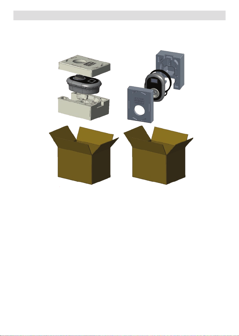
5.1 - BOX CONTENTS FOR CHARGING STATION WITH SOCKET AND CABLE ............................... 11
5.2 - SUPPLIED INSTALLATION EQUIPMENT and ACCESSORIES.................................................. 12
5.3 - PRODUCT INSTALLATION STEPS............................................................................................ 13
5.3.1 - OPENING THE COVER OF THE CHARGING STATION............................................................................. 13
5.3.2 - WALL MOUNT INSTALLATION...................................................................................................................... 14
5.3.3- SINGLE PHASE CHARGING STATION AC MAINS CONNECTION......................................................... 17
5.3.4 - THREE PHASE CHARGING STATION AC MAINS CONNECTION.......................................................... 19
5.3.5 - ADJUSTING CURRENT LIMITER.................................................................................................................... 20
5.3.6 - DIP SWITCH SETTINGS.................................................................................................................................... 21
5.3.6.1 - DATA CABLE CONNECTION............................................................................................................................................. 22
5.3.6.2 - EXTERNAL ENABLE INPUT FUNCTIONALITY............................................................................................................. 23
5.3.6.3 - LOCKED CABLE FUNCTION (Model Wth Socket).................................................................................................... 25
5.3.6.4 - POWER OPTIMIZER (REQUIRES OPTIONAL ACCESSORIES).................................................................................. 26
5.3.6.4.1 - Power Optmzer Wth External MID Meter.......................................................................................................... 27
5.3.7 - MODE SELECTION SWITCH SETTINGS ...................................................................................................... 29
5.3.8 - LOAD SHEDDING.............................................................................................................................................. 30
5.3.9 - MONITORING OF WELDED RELAY CONTACTS FAILURE...................................................................... 31
5.3.10 - FACTORY RESET.............................................................................................................................................. 32
5.3.11 - RESETTING LOCAL RFID CARD LIST AND REGISTERING NEW MASTER RFID CARD IN
STANDALONE USAGE MODE..................................................................................................................................... 32
5.3.12 - SETTING ETHERNET PORT OF CHARGER TO STATIC IP IN STANDALONE USAGE MODE....... 33
5.3.13 - WEB CONFIGURATION INTERFACE ENABLE / DISABLE..................................................................... 33
5.4 - OCPP CONNECTION ................................................................................................................ 34
5.4.1 - CONNECT OCPP OVER ETHERNET.............................................................................................................. 34

Englsh - 3Installation guide WWW.DEFENZO.PL
5.5 - COMMISSIONING .................................................................................................................... 36
5.5.1 - CONNECT PC TO THE SAME NETWORK WITH SMART BOARD......................................................... 36
5.5.2 - OPENING WEB CONFIGURATION INTERFACE WITH BROWSER ........................................................ 37
5.5.3 - OPENING WEB CONFIGURATION INTERFACE VIA WIFI HOTSPOT.................................................... 38
5.6 - WEB CONFIGURATION INTERFACE......................................................................................... 39
5.6.1 - MAIN PAGE ......................................................................................................................................................... 39
5.6.2 - CHANGE GENERAL SETTINGS OF THE DEVICE ...................................................................................... 40
5.6.2.1 - Dsplay Language: ............................................................................................................................................................. 40
5.6.2.2 - Dsplay Backlght Settngs: ............................................................................................................................................. 40
5.6.2.3 - Led Dmmng Settngs: .................................................................................................................................................... 41
5.6.2.4 - Standby LED Behavour: ................................................................................................................................................. 41
5.6.2.5 - Dsplay Theme: ................................................................................................................................................................... 42
5.6.2.6 - Dsplay Servce Contact Info: ........................................................................................................................................ 42
5.6.2.7 - Logo Settngs: ..................................................................................................................................................................... 43
5.6.2.8 - Dsplay QR Code: ............................................................................................................................................................... 43
5.6.3 - INSTALLATION SETTINGS .............................................................................................................................. 44
5.6.3.1 - Earthng system: ................................................................................................................................................................ 44
5.6.3.2 - Current Lmter Settngs: ................................................................................................................................................. 44
5.6.3.3 - Unbalanced Load Detecton:......................................................................................................................................... 45
5.6.3.4 - External Enabled Input: ................................................................................................................................................... 45
5.6.3.5 - Lockable Cable:................................................................................................................................................................... 46
5.6.3.6 - Chargng Mode Selecton and Power Optmzer Confguraton: ..................................................................... 46
5.6.3.7 - Locaton................................................................................................................................................................................. 47
5.6.3.8 - Load Sheddng Mnmum Current............................................................................................................................... 47
5.6.4 - CHANGE OCPP SETTINGS OF THE DEVICE .............................................................................................. 48
5.6.5 - CHANGE NETWORK INTERFACES SETTINGS OF THE DEVICE............................................................ 49
5.6.6 - CHANGE STANDALONE MODE SETTINGS OF THE DEVICE ................................................................ 51
5.6.7 - LOCAL LOAD MANAGEMENT OF THE DEVICE........................................................................................ 52
5.6.7.1 - Modbus TCP/IP Protocol Parameters........................................................................................................................... 52
5.6.7.2 - Statc Management........................................................................................................................................................... 52
5.6.7.3 - Dynamc Management .................................................................................................................................................... 52
5.6.7.4 - Star Topology....................................................................................................................................................................... 53
5.6.7.4.1 - Statc Supply Star Topology: ..................................................................................................................................... 53
5.6.7.5 - Chargng Staton Role....................................................................................................................................................... 54
5.6.7.5.1 - Confguraton of Slave Chargng Statons............................................................................................................ 54
5.6.7.5.2 - Confguraton of Master Chargng Staton .......................................................................................................... 56
5.6.7.6 - Equally shared..................................................................................................................................................................... 59
5.6.7.7 - FFo (Frst n - Frst Out)..................................................................................................................................................... 59
5.6.7.8 - Combned Load Management...................................................................................................................................... 60
5.6.8 - MAKING SYSTEM MAINTANENCE OF THE DEVICE................................................................................ 63
5.6.9 - FIRMWARE UPDATE SCREEN FLOW (Wth Dsplay Models) .............................................................. 64

Englsh - 4 WWW.DEFENZO.PL Installation guide
1 SAFETY INFORMATION
CAUTION
RISK OF ELECTRIC SHOCK
CAUTION: ELECTRIC VEHICLE CHARGER DEVICE SHALL BE MOUNTED BY A LICENSED OR AN EXPERIENCED
ELECTRICIAN AS PER ANY REGIONAL OR NATIONAL ELECTRIC REGULATIONS AND STANDARDS IN EFFECT.
CAUTION
AC mans connecton and load plannng of the electrc vehcle chargng devce
shall be revewed and approved by authortes as specfed by the regonal or
natonal electrc regulatons and standards n eect.
For multple electrc vehcle charger nstallatons the load plan shall be establshed accordngly.
The manufacturer shall not be held lable drectly or ndrectly for any reason whatsoever n the event of damages
and rsks that are borne of errors due to AC mans supply connecton or load plannng.
IMPORTANT - Please read these instructions fully before installing or operating
1.1 - SAFETY WARNINGS
• Keep this manual in a safe place.These safety and operating instructions must be kept in a safe place
for future reference.
• Check that the voltage marked on the rating label and do not use charging station without appropriate
mains voltage.
• Do not continue to operate the unit if you are in any doubt about it working normally, or if it is damaged
in any way - switch off the mains supply circuit breakers (MCB and RCCB). Consult your local dealer.
• The ambient temperature range should be between –35 °C and +55 °C without direct sunlight and
at a relative humidity of between 5 % and 95 %. Use the charging station only within these specified
operating condition.
• The device location should be selected to avoid excessive heating of the charging station. High
operating temperature caused by direct sunlight or heating sources, may cause reduction of charging
current or temporary interruption of charging process.
• The charging station is intended for outdoor and indoor use. It can also be used in public places.
• To reduce the risk of fire, electric shock or product damage, do not expose this unit to severe rain,
snow, electrical storm or other severe weathers. Moreover, the charging station shall not be exposed
to spilled or splashed liquids.
• Do not touch end terminals, electric vehicle connector and other hazardous live parts of the charging
station with sharp metallic objects.
• Avoid exposure to heat sources and place the unit away from flammable, explosive, harsh,
orcombustible materials, chemicals, or vapors.
• Risk of Explosion. This equipment has internal arcing or sparking parts which should not be exposed
to flammable vapors. It should not be located in a recessed area or below floor level.
• This device is intended only for charging vehicles not requiring ventilation during charging.
• To prevent risk of explosion and electric shock, ensure that the specified Circuit Breaker and RCD
areconnected to building grid.
• The lowest part of the socket-outlet shall be located at a height between 0,5 m and 1,5 m above
ground level.
• Adaptors or conversion adapters are not allowed to be used. Cable extension sets are not allowed
to be used.

Englsh - 5Installation guide WWW.DEFENZO.PL
WARNING: Never let people (ncludng chldren) wth reduced physcal, sensory or mental
capabltes or lack of experence and or knowledge use electrcal devces unsupervsed.
CAUTION: Ths vehcle charger unt s ntended only for chargng electrc vehcles not
requrng ventlaton durng chargng.
1.2 - GROUND CONNECTION WARNINGS
• Chargng staton must be connected to a centrally grounded system.The ground conductor enterng
the chargng staton must be connected to the equpment groundng lug nsde the charger. Ths
should be run wth crcut conductors and connected to the equpment groundng bar or lead on
the chargng staton. Connectons to the chargng staton are the responsblty of the nstaller and
purchaser.
• To reduce the rsk of electrcal shock, connect only to properly grounded outlets.
• WARNING : Make sure that during installing and using, the charging station is constantly and properly
grounded.
1.3 - POWER CABLES, PLUGS and CHARGING CABLE WARNINGS
• Be sure that charging cable is Type 2 socket compatible on charging station side.
• A damaged charging cable can cause fire or give you an electric shock. Do not use this product if the
flexible Charging cable or vehicle cable is frayed, has broken insulation, or shows any other signs of
damage.
• Ensure that the charge cable is well positioned thus; it will not be stepped on, tripped over, or
subjected to damage or stress.
• Do not forcefully pull the charge cable or damage it with sharp objects.
• Never touch the power cable/plug or vehicle cable with wet hands as this could cause a short circuit
or electric shock.
• To avoid a risk of fire or electric shock, do not use this device with an extension cable. If the mains cable
or vehicle cable is damaged it must be replaced by the manufacturer, its service agent, or similarly
qualified persons in order to avoid a hazard.
1.4 - WALL MOUNTING WARNINGS
• Read the instructions before mounting your charging station on the wall.
• Do not install the charging station on a ceiling or inclined wall.
• Use the specified wall mounting screws and other accessories.
• This unit is rated for indoor or outdoor installation. If this unit is mounted outdoors, the hardware for
connecting the conduits to the unit must be rated for outdoor installation and be installed properly
to maintain the proper IP rating on the unit.

Englsh - 6 WWW.DEFENZO.PL Installation guide
2 GENERAL INFORMATION
2.1 - INTRODUCTION OF THE PRODUCT COMPONENTS
Socket Equpped Models Tethered Cable Models
3
2
1
5
6
9
44
8
5
3
2
1
6
7
10
9 8
7
Figure-1
EN Socket Models
1. Information Display (Optional)
2. RFID Card Reader
3. Status indicator LED
4. Access cover for residual current
device (Optional)
5. Socket Outlet
6. Product Label
7. Charging station
communication cable gland nut
8. Charging station
communication cable gland nut
9. Charging station supply inlet
gland nut
EN Tethered Cable Models
1. Information Display (Optional)
2. RFID Card Reader
3. Status indicator LED
4. Access cover for residual current
device (Optional)
5. Dummy Socket
6. Charging Plug
7. Product Label
8. Charging cable
9. Charging station
communication cable gland nut
10.Charging station supply inlet
gland nut

Englsh - 7Installation guide WWW.DEFENZO.PL
2.2 - DIMENSIONAL DRAWINGS
2.2.1 - Without Display Model
315.0
460.0
135.0
177.5
101.0
181.0
135.0
177.5
101.0
181.0
RCCBMID
Figure-2
2.2.2 - With Display Model
315.0
460.0
135.0
177.5
101.0
181.0
135.0
177.5
101.0
181.0
RCCBMID
Figure-3

Englsh - 8 WWW.DEFENZO.PL Installation guide
3 REQUIRED EQUIPMENT, TOOLS AND ACCESSORIES
Drill Bit 8mm Impact Drill PC
T25
Volt Indicator Torx T25 Security
Screwdriver Water Level
Flathead Screwdriver
(Tip width 2.00-2.5 mm) Pointed Spudger Right Angle Screwdriver Adapter
/ Torx T20 Security Bit
RJ45 Crimping Tool Cat5e or cat6 ethernet
cable
Table-1

Englsh - 9Installation guide WWW.DEFENZO.PL
4 TECHNICAL SPECIFICATION
This product is compliant to IEC61851-1 (Ed3.0) standard for Mode 3 use.
Model Defenzo Wallbox AC22 Smart
IEC Protection class Class - I
Vehicle
Interface
Socket Model Socket TYPE 2 (IEC 62196)
Cable Model Cable with TYPE 2 ( IEC 62196) Female Socket
Voltage and Current Rates 400 V AC 50/60 Hz
- 3-phase 32 A
AC Maximum Charge Output 22 kW
Idle Power Consumption 3.5 W
Built-in Residual Current
Sensing module 6 mA
Required Circuit Breaker on
AC Mains 4P - 40 A MCB Type-C
Required Leakage Current
Relay on AC Mains (for
products which are not
equipped with RCCB Type A)
4P - 40 A - 30 mA RCCB
Type-A
Required AC Mains Cable 5x 6 mm² (< 50 m) External Dimensions: Ø 18–25 mm
CONNECTIVITY
Ethernet 10/100 Mbps Ethernet (Standard with Smart Options)
Wi-Fi (Optional) Wi-Fi 802.11 a/b/g/n/ac
Bluetooth (Optional) BT 4.2/BT 5.0
OTHER FEATURES (Connected Models)
Diagnostics WebconfigUI
Software Update WebconfigUI update
AUTHORIZATION
RFID ISO-14443A/B and ISO-15693

Englsh - 10 WWW.DEFENZO.PL Installation guide
MECHANICAL SPECIFICATIONS
Material Plastic
Product size 315 mm (Width) x 460 mm (Height) x 135 mm (Depth)
Dimensions (with package) 405 mm (Width) x 530 mm (Height) x 325 mm (Depth)
Product weight 5 kg for socket equipped model,
6.8 kg for tethered cable model (3 Phases)
Weight with package 7,1 kg for socket equipped model,
8.9 kg for tethered cable model (3 Phases)
AC Mains Cable Dimensions For three-phase models Ø 18-25 mm
Cable Inlets AC Mains / Ethernet / Modbus
ENVIRONMENTAL TECHNICAL SPECIFICATIONS
Protection Class Ingress Protection
Impact Protection
IP54
IK10 (Optional display have IK08 protection)
Usage Conditions Temperature
Humidity
Altitude
-35 °C to 55 °C (without direct sunlight)
5% - 95% (relative humidity, non-condensing)
0 - 4,000 m
Englsh - 11Installation guide WWW.DEFENZO.PL
5 INSTALLING CHARGING STATION
5.1 - BOX CONTENTS FOR CHARGING STATION WITH SOCKET AND CABLE
Socket Equpped Models Tethered Cable Models
Figure-4

Englsh - 12 WWW.DEFENZO.PL Installation guide
5.2 - SUPPLIED INSTALLATION EQUIPMENT and ACCESSORIES
Accessory/Material Name Use For Quantity Picture
Dowels (M8x50 Plastic Dowels) Mounting charging station to the wall 4
Torx T25 Security Screw
(M6x75) Mounting charging station to the wall 4
Gasket for screw 6x75 IP for screws which are used for
mounting charging station to the Wall. 4
Torx T20 Security L-Wrench IP for screws which are used for mounting
charging station to the Wall. 1
Wrench Disassembling and fastening the cable
glands 1
Mounting Template Mounting the charging station to the wall 1
O-Ring Mounting the charging station to the pole 3
Screw M6X20 Mounting the charging station to the pole 3
Screw M6X30
Mounting and providing earth continuity for
the charger, that mounts to metal surface.
This screw should be mounted to the right-
down hole of charging station to the Wall.
Below this screw, there should be rubber
under it to fix the ground cable.
1
IP Rubber
Fixing the ground cable with the screw
M6x30. This rubber should be placed to
right-down Wall mount hole of charging
station, under the ground cable and screw
M6x30
1
User RFID Card Start&Stop Charging 1
Master RFID Card Adding&Removing the User RFID Cards to
Local RFID List 1
Instruction Book User Manual 1 Set
Table-2
Englsh - 13Installation guide WWW.DEFENZO.PL
5.3 - PRODUCT INSTALLATION STEPS
CAUTION!
• Ensure that ground resistance of the installation less than 100ohms.
• Prior to mounting your charging station on the wall, read these instructions.
• Do not mount your charging station to the ceiling or an inclined wall.
• Use the wall mounting screws and other accessories specified.
• This charging station is classified as indoor and outdoor installation compatible. If the device is
installed outside the building, the hardware that will be used to connect the cables to the charger
shall be compatible with outdoor use and the charging station shall be mounted preserving the IP
rate of the charger.
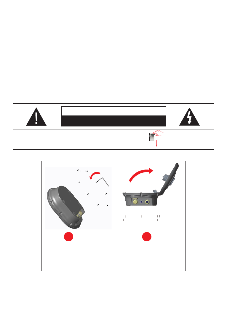
5.3.1 - OPENING THE COVER OF THE CHARGING STATION
CAUTION
RISK OF ELECTRIC SHOCK
Please power o the chargng staton mans supply
1 2
1. Remove the cover screws with Torx T20 security L-Wrench or Right
Angle Screwdriver Adapter using Torx T20 Security Bit.
2. Open the cover.
Englsh - 14 WWW.DEFENZO.PL Installation guide
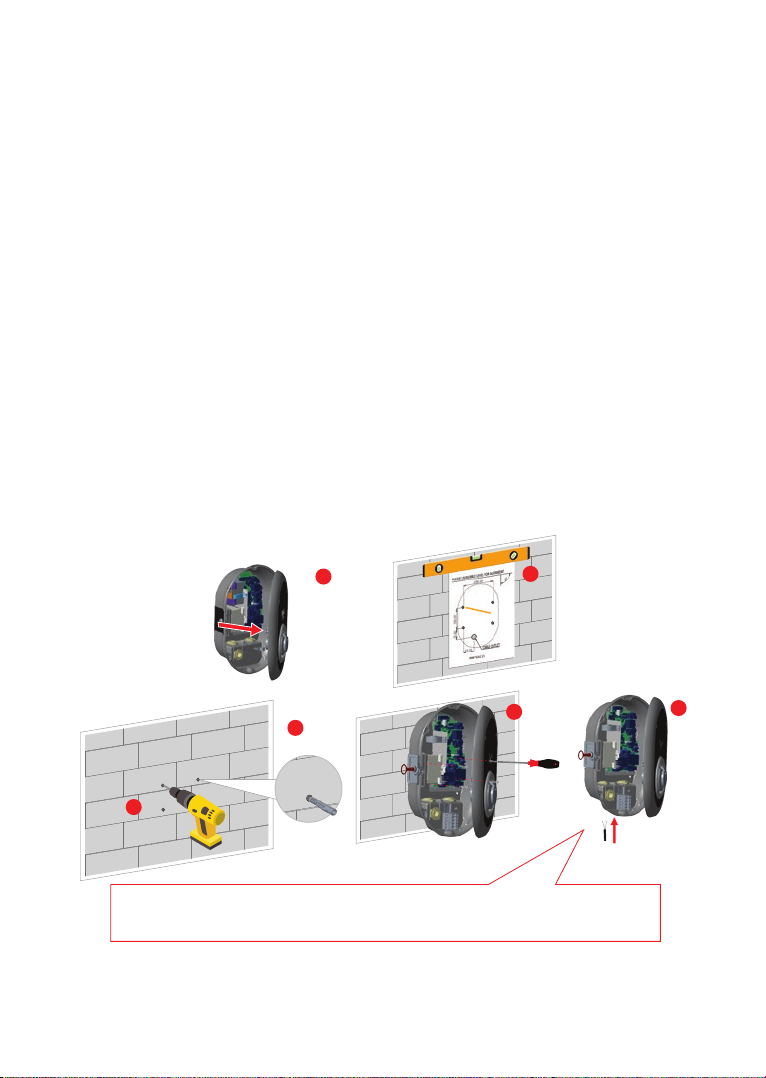
5.3.2 - WALL MOUNT INSTALLATION
Wall mount installation is common for all charging station models.
1. Open the product front cover by following the instruction.
2. Place the charging station to the Wall by using the mounting template which is given in accessory
bag and mark the drill bit holes with a pencil.
3. Drill the wall on the marked points using the impact drill (8mm drill bit).
4. Place the dowels into the holes.
5. Tighten the security screws (6x75) of the product using Torx T25 Security Screwdriver.
6. Insert the AC mains cable into the charging station from the left cable gland which below the
station. Follow the AC Mains Connection instructions on the next pages, depending on the model
of the charger. (Single/Three Phase)
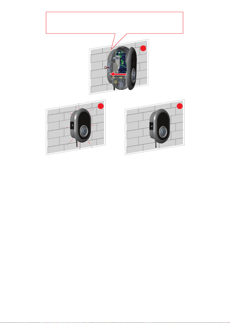
7. In case you mount the charging station to conductive metal surface such as metal pole etc…, you
can make ground connection via“right-bottom” screw using ground extension cable as shown in
figure-6. To ensure the grounding, you need to change the grounding cable position from“a”to “b”
as shown in figure-6. Follow the instructions below:
I. Insert the plastic support (IP rubber which is given inside accessory pack of the unit), to the
fixing hole (Position“b”)
II. Fix the grounding cable using M6x30 screw, which is inside the artwork pack and this screw is
also used to assemble to product to the conductive metal surface.
8. Tighten the cable glands as shown in the figure. Before closing the cover of the charging station,
follow the instructions in next sections if any function related to these sections are used.
9. To close the cover of the charging station, tighten the cover screws which you were removed with
Torx T20 Security L-Wrench or Right Angle Screwdriver Adapter using Torx T20 Security Bit.
10.Mounting the charging station on the wall is finished.
2
1
5
3
4
6
Before closing the cover of the charging station, check next instructions if any
function related to these sections are used.
Figure-5

Englsh - 15Installation guide WWW.DEFENZO.PL
7
b
a
Figure-6
8
AC Mains
Cable
Data cable
Wrench
Wrench
Figure-7
Englsh - 16 WWW.DEFENZO.PL Installation guide
9
9 10
Before next step (7), Please check the nstructons for Sngle Phase
or Three Phase cable connectons.
Figure-8
Englsh - 17Installation guide WWW.DEFENZO.PL
5.3.3- SINGLE PHASE CHARGING STATION AC MAINS CONNECTION
1
1
2
Figure-9
1. Insert the cables to the terminal block as shown in the image. Check the table-3 below to match
Electric Terminal number with AC Cable Color.
2. Tighten the screws on the terminal block as shown in the image with the tightening tourqe of 2.5Nm.
Electric Terminal AC Cable Color
1 AC L1 (Brown)
2 AC Neutral (Blue)
3 Earth (Green-Yellow)
Table-3

Englsh - 18 WWW.DEFENZO.PL Installation guide
For single phase IT Grid installation, wiring diagram which is shown below should be used. Also grounding
type should be set to“IT Grid”from the ”Installation settings”menu in web user interface.

Englsh - 19Installation guide WWW.DEFENZO.PL
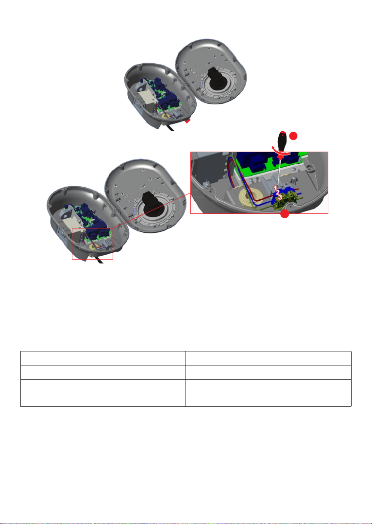
5.3.4 - THREE PHASE CHARGING STATION AC MAINS CONNECTION
1
1
2
Figure-10
1. Insert the cables to the terminal block as shown in the image. Check the table-4 below to match
Electric Terminal number with AC Cable Color.
2. Tighten the screws on the terminal block as shown in the image with the tightening tourqe of 2.5Nm.
Electrc Termnal AC Cable Color
1 AC L3 (Grey)
2 AC L2 (Black)
3 AC L1 (Brown)
4 AC Neutral (Blue)
5 Earth (Green-Yellow)
Table-4
If the three phase charging station is requested to be installed as single phase, phase cable connection
should be done to L1 terminal as shown in figure-9.

Englsh - 20 WWW.DEFENZO.PL Installation guide
5.3.5 - ADJUSTING CURRENT LIMITER
The charging station has current limiter (rotary switch) on the mainboard which is shown in figure-11.
This switch is used for adjusting the current and power of charging station. The arrow in the middle of
the rotary switch must be adjusted gently by rotating with a flathead screwdriver to the position of the
required current rate. The details of the current rates are desicribed in table- 5.
SW2
SW2
0
1
2
3
4
5
6
7
8
9
A
B
C
D
E
F
Figure-11
Required Circuit Braker on AC Mains
EV Charging Station
Current Limiter Setting C-Curve MCB
10 A 13 A
13 A 16 A
16 A 20 A
20 A 25 A
25 A 32 A
30 A 40 A
32 A 40 A
Table-6
Current
Limiter
Position
Current Limit Value
Phase 22 kW 11kW 7.4kW
0
1-
Phase
10 A 10 A 10 A
1 13 A 13 A 13 A
2 16 A 16 A 16 A
3 20 A 20 A
4 25 A 25 A
5 30 A 30 A
6 32 A 32 A
7
8
3-
Phase
10 A 10 A
9 13 A 13 A
A 16 A 16 A
B 20 A
C 25 A
D 30 A
E 32 A
F
Table-5
Other manuals for Wallbox AC22 Smart
1
Table of contents
Other Defenzo Batteries Charger manuals


