Defi DF05101 User manual
DF05101
De-Link Meter
De-Link Meter BF
1
1
1
1
1
1
11
De-Link Display Operations Manual
This display is a valuable additional meter for providing information to automobile users about engine conditions and other
important factors. When installing and operating this product, be sure to read the cautionary items of this operations manual as
well as those given in the operations manual for the vehicle in which this display will be installed. Obtain a full understanding of
the cautionary items and use the product accordingly.
In this manual, the degree of hazard arising from actions such as improper operation is separated into the 2 levels“Warning” and
“Caution.” In addition, instructions that must be followed for safe and proper use of this product as well as practices that must be
maintained are marked with a “Check” heading. Please read and become familiar with these sections.
In the event that this product (or the vehicle in which it is installed) is lent to or transferred to another person, please be sure this
operations manual accompanies the product.
Before Installation (for installation personnel)
lBe sure to follow all instructions in this manual to ensure safe installation and operation of the product.
lCarefully consider the installation location and driver’s operation of the product before installation. Be
sure not to install the unit where it could fall. Improper installation or operation could cause the
product to fall and damage the vehicle or present the severe danger of impeding driving of the vehicle.
lDo not disassemble or modify this product. Such actions can not only damage or destroy the product
but will also void the warranty.
lDo not perform installation of this product immediately after the engine has been switched o. The
engine and exhaust system are extremely hot at this time and can cause burns if touched.
lEnsure that the wiring of this product does not have an adverse impact on the other wiring of the vehicle. The controller or
other electronic components of the vehicle could be damaged.
lPlease keep children and infants away from the installation area. Children may swallow small parts or be injured in other
ways.
Warning
disassemble/
modify
lThis product is designed for use on 12V vehicles. Do not install this product on vehicles with 24V
systems.
lDo not install the display in a location with much moisture or dust, or where it will be in direct sunlight,
or in an area around heater exhaust vents.
lWear gloves to avoid burns when soldering and cuts when working with wiring.
lWhen the negative (-) battery terminal is disconnected, equipment such as clocks and audio
components having internal memory may lose their memory data. Follow the operations manual of each component to
reset data after installation of this product.
Caution
24 V
lAfter installation is complete, return this operations manual to the customer along with the warranty.
Conrmation
About Installation and Operation
(for customer and installation personnel)
Warning
lPlease have this product installed by the retail store or dealer where it was purchased. Installation by
the customer will void the warranty.
lDo not disassemble or modify this product. Such actions can not only damage or destroy the product
but will also void the warranty.
lIn order to ensure safe driving, check the information on this display only for short periods of time.
Looking at the display for long periods of time could distract adequate attention from the road and
result in an accident.
lDiscontinue use of this product if nothing is displayed, water gets into the unit, or smoke or a strange odor comes from the
unit. If such a condition occurs, contact the sales outlet or installation personnel as soon as possible. Continued use while
the condition exists could result in an accident or re.
disassemble/
modify
lThe De-Link Display will not operate without connection to De-Link Control Unit II or De-Link Control Unit.
lWhen De-Link Meters or De-Link BF Meters are connected, a maximum of 7 components can be connected, including
De-Link Display.
lSee the De-Link System operations manual for installation of De-Link sensors.
lOnly the Speed Mode will be shown on the De-Link Display when no other sensors are connected to De-Link Control
Unit II or De-Link Control Unit. In that case, PEAK Mode and REPLAY Mode will not be available.
lBe sure the speed signal wire is connected when using this display.
Caution
Main Features (for customer)
lThis product is a multi-purpose monitor for connection to De-Link Control Unit II or De-Link Control Unit. It uses an
organic light emitting diode made by Nippon Seiki.
lThe monitor’s display uses optimal technology for instant readability without afterimages or icker even when seen from
the passenger’s seat or in daylight.
lReal-time digital information includes speed, oil temperature, water temperature, oil pressure, fuel pressure and exhaust
temperature.
lVehicle performance data and peak values are placed in memory for 3 minutes, allowing examination of data after running
the vehicle.
* De-Link Control Unit II has a 3 minute memory. De-Link Control Unit has a 40 second memory.
lWhen the RPM signal wire is connected to De-Link Control Unit II or De-Link Control Unit, 2 warning levels can be set in
addition to the warning setting made by Control Unit II or Control Unit, enabling the setting of a total of 3 warning levels.
(Tachometer Triple Warning Mode)
lWhen the water temperature sensor is connected, the warm-up condition can be monitored.
lA graphic animation plays after the ignition is turned on or o. (Opening Mode/Ending Mode)
lAn easily recognizable graphic on each setting screen helps guide easy setting of warnings for De-Link Meters and Step
Graph. (Setting Assistance function)
lThe Warning LED lights when the set warning value is exceeded for oil temperature, water temperature, exhaust
temperature and engine RPM. TheWarning LED lights when measured value drops below the set warning value for oil
pressure and fuel pressure.
lTrouble locations are shown by graphics so that connection problems can be quickly corrected. (Self-Diagnosis function)
lThe structure of the mounting base allows height and angle adjustment so that it can match the shape of the instrument
panel.
lThe De-Link Indicator (sold separately) can be connected to the display.
The following parts are included with this product. Conrm that all parts are present before installing the product. In addition,
these parts are sold separately for part replacement, so contact your retailer for further information.
Parts List (for customer and installation personnel)
Part Name Quantity
Included Parts Set for Meters
(double-sided tape, buer, mounting bracket,
M4 bolt & nut, washer)
Operations Manual
Installation Stay
Set Screw Solderless Connector
Meter Wire (25cm)
Speed Signal Wire (2m)
QuantityPart Name
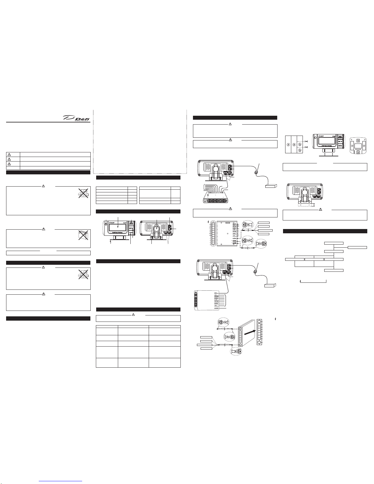
Part Names (for customer and installation personnel)
Warning LED
(Front Side) (Rear Side)
* Organic Light Emitting Diode Display (32 x 80 Full Dot)
Mounting Bracket
MODE SELECT Button
SET UP
Button
Installation Stay
ENTER Button
Set Screw
4 Pin Connectors for Meter Wire
(Doesn't matter which is connected.)
3 Pin Connector for
De-Link Indicator
2 Pin Connector for Speed
Signal Wire
* LICENSED PRODUCT by KODAK
Product Specications (for customer and installation personnel)
lPower Supply Voltage 8.5 V to 13.5 VDC
(For 12 V vehicles, voltage supplied by De-Link Control Unit II or De-Link Control
Unit.)
lCurrent Consumption ILM ON MAX 0.2 A
ILM OFF MAX 0.2 A
lOperational Temperature Range -20 to +60 C, +14 to +140 F (under 80% relative humidity)
lStorage Temperature Range -40 to +80 C, -22 to +176 F (under 80% relative humidity)
lDisplay Range • Speedometer 0 to 400 km/h, 0 to 240 MPH
• Oil Temperature Meter 50 to 150 C, 122 to 302 F
• WaterTemperature Meter 20 to 120 C, 68 to 248 F
• Oil Pressure Meter 0 to 1,000 kPa, 0 to 145 PSI
• Fuel Pressure Meter 0 to 600 kPa, 0 to 87 PSI
• Exhaust Temperature Meter 200 to 1,100 C, 390 to 2,010 F
lCorresponding Speed Pulse 2, 4, 8, 16, Pulse Free
lDimensions (mm) 34 (W) x 103 (D) x 46 (H) (not including mounting base)
lGross Weight 290g, 2/3 lb (including display, wires, mounting bracket, packaging)
Control Unit
To De-Link Meter
To De-Link Indicator
To PowerSource
To Sensors
The display can be directly connected to either the Control Unit (see gure below) or De-Link Meters.
lWhen connected to De-Link Control Unit
Solderless Connector
Speed Signal Wire
Meter
Wires
Speed signal wire of engine
computer unit of the vehicle(ECU)
* When illumination is on, screen brightness will be
reduced by 1 level.
ECU
Control Unit II
Control Unit II
(Rear Side Enlarged Diagram)
M-WARNING
TACHOMETER
WATER TEMP.
EXHAUST TEMP.
OIL TEMP.
FUEL PRESS.
OIL PRESS.
TURBO (BOOST)/
INTAKE MANIFOLD PRESS.
DC SOURCE
METER OUTPUT 1
METER OUTPUT 2
Connector Colors
Power Wire
Meter Wire
Sensor Wire Installation Positions
Red wire - Battery
Orange wire - IGN
(To 12V battery wire)
(To 12V wire when ignition on)
White wire - Illumination
Black wire - GND
(To 12V wire when small lamp on)
(To ground, negative battery terminal)
(white)
(white)
(blue)
(black)
(white)
(blue)
(black)
(white)
(white)
(black)
(white)
lWhen installing or working with the display, be sure to follow the applicable instructions for either De-Link Control Unit II
or De-Link Control Unit as shown in their corresponding manuals.
Caution
To De-Link Meter
Meter
Wire
To De-Link Indicator
Solderless Connector
Speed Signal Wire
To Sensors
M-WARNING
To Pow er
Source
To De-Link Meter BF
Control Unit II
Speed signal wire of engine
computer unit of the vehicle (ECU)
* When connected to Meter Output 1, turning the Illumination
on will reduce screen brightness by 1 level.
When connected to Meter Output 2, screen brightness can be
adjusted independently for daytime by 5 levels and nighttime
by 5 levels.
*
The display can be connected to any of De-Link Control Unit II(see gure below), De-Link Meter and De-Link Meter BF.
Switching the lighting between the daytime mode and nighttime mode is interlocked with the illumination switch of the
vehicle.
ECU
lWhen connected to De-Link Control Unit II
lBe sure to connect the speed signal wire to this product. If the speed signal wire is not connected, the display will stay in
the Special Display Mode.
Caution
l
Carefully read the“Before Installation”and “About Installation and Operation” sections of the manual concerning installation and
operation. Then install the product properly and safely.
l
Installation in an unsuitable location or improper installation can result in the product falling from its position or damage to the vehicle.
* Open terminals are used for inspection of the product, so never connect wiring to these terminals. Connection to these terminals can
damage the product.
Warning
[Wiring Diagram]
Installation (for installation personnel) lInstalling the Mounting Bracket
1. Cut the supplied double-sided tape. [Figure 1]
2. Insert the protrusions of the mounting bracket into the slots of the meter holder, then secure with the supplied bolt and nut.
[Figure 2]
3. Attach the supplied double-sided tape to the underside of the mounting bracket. Align the mounting bracket with the
location for unit installation, then bend the mounting bracket to the shape of the location while pressing down so the tape
will adhere. To prevent the unit from falling o, secure the mounting bracket with commercially available self-tapping screws.
[Figure 1]
lAdjusting the height of the installation stay.
Turn the set screw to adjust position on the installation stay so the display is easy to see. (Position can shift up or down by
9.5mm.)
lBefore attaching the mounting bracket to the dashboard, thoroughly clean the mounting surface with a commercial
dashboard cleaner to remove dust, dirt and oils.
Conrmation
[Figure 2] [Figure 3]
lBe sure to secure the installation stay in place with the set screw.
If the screw is tightened up without the stay being placed between, it can damage the parts and cause failure of the
product.
Caution
lIllustration of set modes and functions.
[Operational Status Transition Diagram]
Operation (for customer)
SET UP Button
Opening Mode
Set Up Mode
MODE SELECT Button
Warm-Up Mode
Ending Mode
Gauge ModeSpeed ModeTriple Warning Mode
* When water temperature
sensor is connected.
• Warning Settings
• Peak
• Replay
• Warning Settings
• Peak
• Replay
• Warning Settings
• Peak
• Replay
After completion of Opening Mode, Warm-Up Mode elapses and the unit shifts toTriple Warning Mode/Speed Mode/
Gauge Mode. The initial setting is Gauge Mode. Each time the MODE SELECT button is pressed, the mode changes
consecutively to Gauge Mode ÞSpeed Mode ÞTriple Warning Mode.
* Triple Warning Mode is not available when connected to De-Link Meter BF.
* Only Speed Mode is available if there are no sensors connected to the De-Link Control Unit II or
De-Link Control Unit. In addition, Peak Mode and Replay Mode will not function.
* Be sure to connect the speed signal wire when using this product.
De-Link Display
Red Orange
Empty
Black
White
Yellow
Orange
Black
Yellow Black
White
Orange White
Max of 9.5mm up/down
shift possible.
Condition Possible Cause Corrective Action
• Does not display.
• Triple Warning Mode
cannot be set.
• Cannot adjust illumination
of display.
• A line does not light in the
display.
• A button does not operate.
• A dot that should not light
is lighting.
• Speed is not being
recorded.
• Wiring is improper.
• Display is connected to Meter Output 2 of
De-Link Control Unit II.
• Display is connected to Meter Output 1 of
De-Link Control Unit II.
• De-Link Display is damaged.
• The REC button of De-Link Control Unit II
or REC/PLAY button of De-Link Control
Unit has been pressed while the vehicle is
stopped.
• Check wiring as per instructions in De-Link
Control Unit II or De-Link Control Unit
operations manual.
• Connect Display to Meter Output 1 of
De-Link Control Unit II.
• Connect Display to Meter Output 2 of
De-Link Control Unit II.
• Contact the retail outlet where the unit was
purchased.
• This is normal for the product.
Press REC button or REC/PLAY button while
the vehicle is moving.
lIf operation of the product seems unusual, inspect the product to conrm that it is not malfunctioning. If an operational
problem has occurred, it could result in an accident.
* In addition to a general inspection of the product, use the following table to conrm proper operation of the unit.
Warning
Troubleshooting (for customer and installation personnel)
Control Unit
(Rear Side)
Power Wire
Control Unit (Rear Side)
Enlarged Diagram
TACHOMETER
(White)
WATER TEMP.
(Blue)
EXHAUST TEMP.
(Black)
OIL TEMP.
(White)
FUEL PRESS.
(Blue)
OIL PRESS.
(Black)
TURBO (BOOST)/
(White)
INTAKE MANIFOLD PRESS.
Sensor Wire Installation Positions
Meter Wire
(White)
DC SOURCE
(White)
Red wire - Battery
White wire - Illumination
Orange wire - IGN
(To 12V battery wire)
(To 12V wire when ignition on)
Black wire - GND
(To 12V wire when small lamp on)
(To ground, negative battery terminal)
Connector Colors
Meter Wire
Black
Empty
Orange Red
White
Orange
Yellow
White
Black
OrangeWhite
YellowBlack
Caution
Warning
Confirmation
Danger indicates an imminently hazardous situation which, if not avoided, will result in death or
serious injury.
indicates a potential hazardous situation which, if not avoided, could result in death or
serious injury.
indicates a potentially hazardous situation which not avoided, may result in minor or
moderate injury. It may also be used to alert against unsafe practices.
Indicates an instruction that must be performed or practice that must be maintained.
to change units
to set the units
Press and hold
Temperature Setting
Gauge Setting
used to
select On selection
used to
set
pressed once raises value by 1C
pressed and held raises value by 5C
used to set value
Warm-Up Setting
used to
set
used to
select
Single Dual
pressed once raises value by 100 RPM
pressed and held raises value by 500 RPM
used to set value. ThenWARN. 2 will light.
pressed once raises value by 100 RPM
pressed and held raises value by 500 RPM
used to set value. ThenWARN. 1 will light.
TATriple Warning 1
* Only when TA signal
is connected
TATriple Warning 2
* WARN. 1 setting range:
1000 to 11000 RPM
* WARN. 1 factory setting:
7000 RPM
* WARN. 2 setting range:
WARN.1 WARN. 2 11000 RPM
TURBO
Peak Peak Reset
After 3 minutes
After 3 minutes
No Warning
Under 9000RPM
Warning 1
Over 9000 RPM
Warning 2
Over 10000 RPM
Warning 3
When De-Link Indicator
is connected, the indicator
ashes being interlocked
with the Warning LED.
Warning LED
The Warning LED lights up when theTachometer exceeds the warning value
set up by De-Link Control Unit II or De-Link Control Unit.
Normal
Normal
With Warning generated
With Warning generated
Warning LED
Warning LED
After 40 seconds
After 40 seconds
Peak Peak Reset
Steady Flash
Warning LED
,
Warm-Up CompletedDuring Warm-Up
Displaying Oil Press./WaterTemp.Displaying Speed
Double-sided
tape
wire
Opening Complete
WARN. 1 Lighted
Setting Range
km/h, MPH
kPa/C, PSI/F
2, 4, 8, 16, FREE
ON, OFF
20 to 120C, 68 to 248F
Single, Dual
1000 to 11000 RPM
Warning 1 to 11000 RPM
Display Units
km/h or MPH
kPa/C or PSI/F
—
—
C or F
—
RPM
RPM
Factory Setting
km/h
kPa/C
4 pulse
ON
40C
Single
7000 RPM
8000 RPM
Item
1Speed Units
2Pressure/Temperature Units
3Speed Pulse
4Special Display
5Warm-Up
6Gauge Display
7Tachometer Warning 1
Tachometer Warning 2
Setting Range
-100 to 200 kPa or -14.5 to 29.0 PSI
200 to 1100C or 390 to 2010F
0 to 1000 kPa or 0 to 145 PSI
0 to 600 kPa or 0 to 87 PSI
50 to 150C or 122 to 302F
20 to 120C or 68 to 248F
0 to 11000 RPM
Display Units
C or F
kPa or PSI
kPa or PSI
kPa or PSI
C or F
C or F
RPM
Item
1Turbo Meter
2Exhaust Temp. Meter
3Oil Press. Meter
4Fuel Press. Meter
5Oil Temp. Meter
6Water Temp. Meter
7Tachometer
Button to Press Vehicle’s
Condition
Running
Stopped
Running
Stopped
Record
Play
Record
Play
(Record)
(Play)
Speed Data Displayed on
De-Link Display
REC button
PLAY button
Record
Record
Play
Play
Sensor Data Connected to
Control Unit II
Button to Press Vehicle’s
Condition
Running
Stopped
Running
Stopped
Record
Play
Record
Play
Speed Data Displayed on
De-Link Display
REAL Mode
REC/PLAY button
PEAK Mode
REC/PLAY button
Record
Record
Play
Play
Sensor Data Connected
to Control Unit
Model Number
PDF00713SS
PDF00806SS
PDF00908SS
PDF01006SS
PDF01114SS
Item
De-Link OIL PRESS. Sensor Set
De-Link FUEL PRESS. Sensor Set
De-Link OIL TEMP. Sensor Set
De-Link WATER TEMP. Sensor Set
De-Link EXHAUST TEMP. Sensor Set
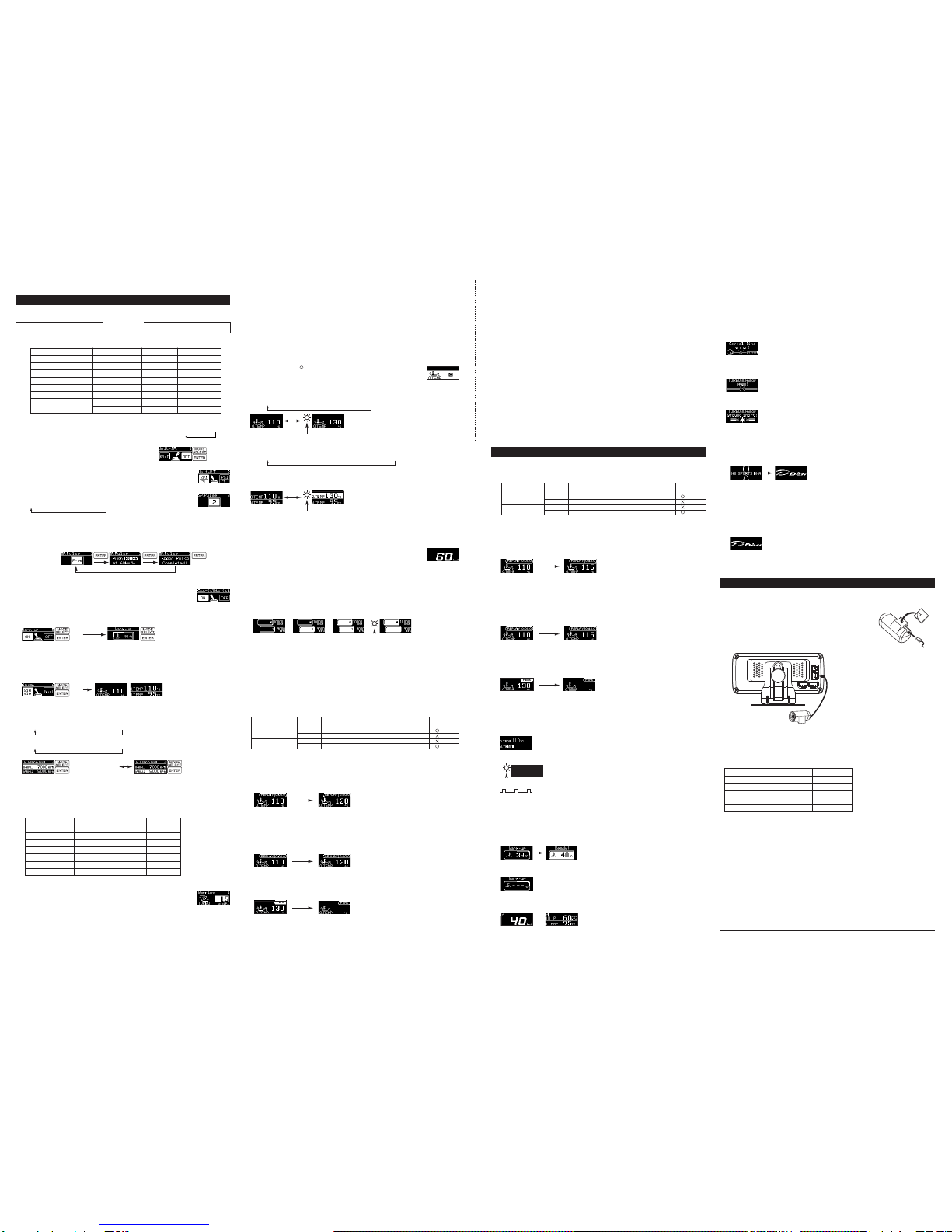
Operation (for the customer)
1. Set Up Mode (Screen for setting units and display data parameters.)
lBe sure to make preparatory settings. The unit will not operate properly without settings being made.
Conrmation
When changing the factory settings shown below, pressing the SET UP button after the Opening Mode has
completed will bring up the setting mode for speed units.
* In Set Up Mode, the item to be set changes each time the ENTER button is pressed.When adjustment of a particular
setting is not needed, press the ENTER button to skip that item.
1
Speed Units Æ2
Pressure Units Æ3
Speed Pulse Æ4
Special Display Æ5
Warm-Up Æ6Gauge Display
7Tachometer Warning 2 ¨7Tachometer Warning 1
1 Setting Speed Units
Use the MODE SELECT button to select Speed Units,
then press ENTER to set the desired units.
km/h €MPH
2Setting Pressure/Temperature Units
Use the MODE SELECT button to select units for the oil pressure/fuel pressure/
oil temperature/water temperature gauges, then press ENTER to set the desired units.
kPa/C €PSI/F
3Setting Speed Pulse
Use the MODE SELECT button to select the speed pulse number, then press ENTER
to set the selection.
4 fi 8 fi16 (pulse) fi2 fi FREE (pulse free)
Speed Pulse Number: The speed pulse number diers by model of vehicle.Consult your local car dealer if you are not
certain of the speed pulse number for your vehicle.
Pulse Free Setting: For vehicles having a speed pulse outside 2, 4, 8, 16 pulse, the speed pulse can be set by
switching to the“Free”screen and then by pressing and holding the ENTER button while the
vehicle is moving at 60 km/h or 40 MPH. After 2 seconds of holding the button, the screen will
change and the speed pulse will be set.
*If the speed units are changed while using Pulse Free, it is necessary to repeat the pulse free
setting steps.
4Setting Special Display
Use the MODE SELECT button to select the special display setting, then press ENTER
to set the selection.
On €O
5Setting Warm-Up (only available when water temperature sensor is connected)
Use the MODE SELECT button to select On or O, then press ENTER to set the selection.
On €O
* When On is selected, each time the MODE SELECT button is pressed, the temperature value setting will increase by 1C and
each time the button is pressed and held, the value will increase by 5C. When the desired temperature value is reached, it is
set by pressing the ENTER button.
6Setting Gauge Display
Use the MODE SELECT button to select display data format, then press ENTER to set the selection.
Single Gauge € Dual Gauge
7Setting Tachometer Warning
1
Setting Tachometer Warning
2
Use the MODE SELECT button to select warning value, then press ENTER to set the value.
Each time the MODE SELECT button is pressed, the value will increase by 100 RPM.
1000 fi1100 fi . . . fi10900 fi 11000 RPM
Each time the MODE SELECT button is pressed and held, the value will increase by 500 RPM.
1000 fi1500 fi. . . fi 10500 fi11000 RPM
3. Gauge Mode
(This screen displays actual vehicle data and speed data for meters
connected to De-Link Control Unit II or De-Link Control Unit.)
* Does not display Turbo Meter data or Tachometer data.
O. TEMP : Oil Temperature Meter W. TEMP : Water Temperature Meter
OIL P. : Oil Pressure Meter FUEL P. : Fuel Pressure Meter
EXT. T. : Exhaust Temperature Meter
Press ENTER to select and adjust the displayed meter.
With the ignition on, a“ ” will be displayed for meters with connected sensors.
A “/”will be displayed for meters without connected sensors, and selection/adjustment
will be unavailable.
1Single Gauge Mode
Each time the MODE SELECT button is pressed, the displayed meter will change. Press ENTER to set the meter for display.
O. TEMP fi W. TEMP fiOIL P. fiFUEL P. fiEXT. T.
2Dual Gauge Mode
Each time the MODE SELECT button is pressed, the displayed meter will change. The upper display is set rst, then the
lower display. Press ENTER to set the meter for display.
O. TEMP fiW. TEMP fi OIL P. fiFUEL P. fiEXT. T. fiSPEED
*For O.TEMP, W.TEMP and EXT T. warnings, if the set warning value is exceeded for the displayed meter, the Warning
LED will light and the corresponding display value will have reverse lighting.
For OIL P. and FUEL P. warnings, if actual value drops below the set warning value, the Warning LED will light and the
corresponding display value will have reverse lighting.
4. Speed Mode (This screen displays the vehicle speed.)
Pressing the MODE SELECT button while in Gauge Mode will bring up the Speed Mode.
Along with display of current vehicle speed, the maximum speed is always monitored
and recorded.
5. Triple Warning Mode
(This screen displays a warning when the Tachometer exceeds the engine RPM set
warning value.)
Pressing the MODE SELECT button while in Speed Mode will bring up the Triple Warning Mode when the RPM signal wire is
connected to De-Link Control Unit II or De-Link Control Unit.
* This mode is not available when connected to De-Link Meter BF.
7. Special Display Mode
(This screen is displayed when speed is 0 Km/h or 0 MPH for more than 10 seconds.)
* Turbo Meter and Tachometer are not displayed.
When Special Display is turned on in Set Up Mode, the peak values for meters having connected sensors are
displayed from the time ignition is on while in Gauge Mode or Speed Mode.
When Special Display is turned o in Set Up Mode, the digital display disappears and the Warning LED ashes at a
steady interval.
* If the Warning LED is lighted while in Gauge Mode, the Special Display Mode cannot be
activated.
2When connected to De-Link Control Unit.
• REC (Recording)
Care must be used in operation because De-Link Control Unit operation diers from De-Link Display; De-Link
Display determines if it should record/play according to vehicle’s running/stopped condition.
Pressing the Control Unit REC/PLAY button in either Gauge Mode, Speed Mode or Triple Warning Mode will start
recording of all data for meters connected to Control Unit and speed data for a maximum of 40 seconds. When 40
seconds elapses, the unit will return to the mode used before recording started.
To stop recording before the 40 second maximum elapses, press the REC/PLAY button again, and the unit will return
to the mode used before recording started.
Speed can be recorded during vehicle running by pressing the REC/PLAY button.
* Recording of speed data will be interrupted if wiring disconnection or short circuit occurs during recording.
* The unit cannot record while the vehicle is stopped even if the REC/PLAY button is pressed.
• PLAY
After recording, pressing the Control Unit REC/PLAY button when PEAK values are being displayed will start playing
of all recorded meter data or speed data for a maximum of 40 seconds. When playing is completed, or when the
REC/PLAY button is pressed again, the unit will return to the mode used before playing started.
Speed can be played by pressing the REC/PLAY button while in PEAK Mode when the vehicle is stopped. If PAUSE is
pressed during speed playback, the unit will return to Real Mode.
*Recording of speed data will be interrupted if wiring disconnection or short circuit occurred during recording.
*The unit cannot play while the vehicle is running even if the REC/PLAY button is pressed.
• PEAK Display
Pressing the Control Unit PEAK/RESET button in either Gauge Mode, Speed Mode or Triple Warning Mode will
display recorded peak values from all meter data or speed data.
Pressing the PEAK/RESET button again will return the unit to the mode used before peak display started.
Pressing the Control Unit PEAK/RESET button for 2 seconds while a peak value is displayed will reset the peak value.
Optional Parts (for customer)
8. Warm-Up Mode
(This screen monitors water temperature until it reaches a set value.)
When Warm-Up is turned on in Set Up Mode and the water temperature sensor is connected to Control Unit II or
Control Unit, the Warm-Up Mode activates after Opening Mode is completed. The “Warm-up” notice and current
water temperature are displayed until the temperature reaches the set value.
When the temperature reaches the set value, the warm-up completed“Ready” notice is displayed for 5 seconds and
the unit returns to the display mode used before the ignition was turned o (Speed Mode, Gauge Mode or Triple
Warning Mode). Factory setting is Gauge Mode.
Water temperature of 20C (68F) or below is displayed as“ - - -”.
If the MODE SELECT button or SET UP button is pressed before water temperature reaches the set value, the unit will
switch to the other mode (except for Warning Setup Mode or Set Up Mode) and a “C” symbol will appear in the
upper left corner of the screen until the temperature reaches the set value.
9. Self-Diagnosis Function
(This screen displays serial errors, opens and shorts for each sensor of meters
connected to De-Link Control Unit II or De-Link Control Unit when ignition is
on. If an error message is displayed, check the item and take appropriate
action.)
1Serial Error Function
This function noties of communications that have been interrupted between the meter and the Control Unit.
2Disconnection (Open) Check Function
This function noties that a wire disruption, disconnection or improper wiring connection has occurred at the sensor
or in the sensor wire.
3Short Circuit Check Function
This function noties that a short circuit has occurred somewhere at the sensor or in the sensor wire.
10. Opening Mode (This screen appears when the ignition is turned on.)
Factory setting is for switch to Warm-Up Mode after Opening Mode is complete.
11. Ending Mode (This screen appears when the ignition is turned o.)
When connected to Meter Output 2 of Control Unit II, display of the Ending Mode screen is
about 2 seconds longer than when connected to Meter Output 1 of Control Unit II or when
connected to Control Unit.
02.9-0.3k
lDe-Link Indicator Model number DF01801
The indicator ashes red when a meter being displayed on the De-Link Display reaches the set warning value.
[Indicator Installation Method (for installation personnel)]
• When used as an indicator for a connected meter.
1. Attach the supplied double-sided tape to the bottom of the indicator body.
(Attach 2 layers of double-sided tape for ø4 1/8" (80 mm) or
ø4 1/2" (115 mm) size meters.)
2. Connect the supplied wire.
3. Attach the Indicator to the meter or the instrument panel.
lDe-Link Sensor Set
Sensor sets include the meter sensor and sensor wire for connection to De-Link Control Unit II or De-Link Control
Unit.
If one of the following sensor sets is connected to De-Link Control Unit II or De-Link Control Unit, De-Link Display
can be used for displaying values even without a meter.
6. REPLAY Display, PEAK Display
(This screen records vehicle data for meters connected to De-Link Control Unit II
or De-Link Control Unit or it replays the recorded data or displays data peaks.)
* Does not display data for Turbo Meter or Tachometer.
1When connected to De-Link Control Unit II.
Care must be used in operation because De-Link Control Unit II operation diers from De-Link Display; De-Link
Display determines if it should record/play according to vehicle’s running/stopped condition.
• REC (Recording)
Pressing the Control Unit II REC button in either Gauge Mode, Speed Mode or Triple Warning Mode will start
recording of all data for meters connected to Control Unit II and speed data for a maximum of 3 minutes. When 3
minutes elapses, the unit will return to the mode used before recording started.
To stop recording before the 3 minute maximum elapses, press the REC button again, and the unit will return to the
mode used before recording started.
Speed can be recorded during vehicle running by pressing the REC button.
• PLAY
Pressing the Control Unit II PLAY button in either Gauge Mode, Speed Mode or TripleWarning Mode will start playing
of all recorded meter data or speed data for a maximum of 3 minutes.When playing is completed, or when the PLAY
button is pressed again, the unit will return to the mode used before playing started.
* If PAUSE is pressed during playback, the time counter display will disappear.
Speed can be played by pressing the PLAY button when the vehicle is stopped. If PAUSE is pressed during speed
playback, the unit will return to Real Mode.
• PEAK Display
Pressing the Control Unit II PEAK button in either Gauge Mode, Speed Mode or Triple Warning Mode will display
recorded peak values from all meter data or speed data.
Pressing the PEAK button again will return the unit to the mode used before peak display started.
Pressing the UP button of Control Unit II while a peak value is displayed will reset the peak value.
2. Warning Setup Mode
(This screen allows setting of warnings for meters connected to
De-Link Control Unit II or De-Link Control Unit.)
* Each time the WARN SET button of De-Link Control Unit II or the SELECT button of De-Link Control Unit is
pressed, the meter available for setting will change in the Warning Setup Mode.
The value of the setting is adjusted by pressing the UP button or DOWN button of
De-Link Control Unit II or De-Link Control Unit.
* The resolution of the UP button or DOWN button is adjusted to the analog meter.
Because of the dierence in step values, the Display value changes dierently in
each meter.
Pressing and holding the button will accelerate the adjustment rate for easier use.
1Turbo Meter Æ2Exhaust Temp. Meter Æ3Oil Press. Meter Æ4Fuel Press. Meter
≠ Ø
7Tachometer ¨6Water Temp. Meter ¨ 5Oil Temp. Mete
* The upper display has priority when REC, PLAY or PEAK is displayed.
* REC, PLAY and PEAK display cannot be used during
Warm-Up Mode.
* REC, PLAY and PEAK display can be used while the“C” symbol is displayed.
Operation (for the customer)
* If PAUSE is pressed during playback, the time counter
display will disappear.
(Record)
(Play)
Other Defi Automobile Accessories manuals

Popular Automobile Accessories manuals by other brands


Bestop
Bestop BestRail 42792 installation instructions

Leer
Leer CAB HIGH SPORT BED CAP Installation instructions & owner's manual

VBG
VBG Onspot Mounting instruction/Spare Parts List

Tronair
Tronair 01-1109-0010 Operation & service manual

Woodway
Woodway Whelen CenCom Sapphire installation guide

SureCall
SureCall Fusion2Go Max Quick setup guide


